EP0189323B1 - Optical fiber termination device having cutting means - Google Patents
Optical fiber termination device having cutting means Download PDFInfo
- Publication number
- EP0189323B1 EP0189323B1 EP86300450A EP86300450A EP0189323B1 EP 0189323 B1 EP0189323 B1 EP 0189323B1 EP 86300450 A EP86300450 A EP 86300450A EP 86300450 A EP86300450 A EP 86300450A EP 0189323 B1 EP0189323 B1 EP 0189323B1
- Authority
- EP
- European Patent Office
- Prior art keywords
- fiber
- housing
- termination
- plug
- optical
- Prior art date
- Legal status (The legal status is an assumption and is not a legal conclusion. Google has not performed a legal analysis and makes no representation as to the accuracy of the status listed.)
- Expired
Links
- 239000013307 optical fiber Substances 0.000 title claims description 25
- 239000000835 fiber Substances 0.000 claims description 64
- 230000003287 optical effect Effects 0.000 claims description 30
- 238000003780 insertion Methods 0.000 claims description 17
- 230000037431 insertion Effects 0.000 claims description 17
- 230000005540 biological transmission Effects 0.000 claims description 10
- 238000002360 preparation method Methods 0.000 description 7
- 238000000429 assembly Methods 0.000 description 4
- 238000000034 method Methods 0.000 description 4
- 239000000463 material Substances 0.000 description 3
- 238000005452 bending Methods 0.000 description 1
- 239000002131 composite material Substances 0.000 description 1
- 238000010276 construction Methods 0.000 description 1
- 239000003365 glass fiber Substances 0.000 description 1
- 230000013011 mating Effects 0.000 description 1
- 230000010287 polarization Effects 0.000 description 1
- 238000005498 polishing Methods 0.000 description 1
- 239000000126 substance Substances 0.000 description 1
- 230000003313 weakening effect Effects 0.000 description 1
Images

Classifications
-
- G—PHYSICS
- G02—OPTICS
- G02B—OPTICAL ELEMENTS, SYSTEMS OR APPARATUS
- G02B6/00—Light guides; Structural details of arrangements comprising light guides and other optical elements, e.g. couplings
- G02B6/24—Coupling light guides
- G02B6/36—Mechanical coupling means
- G02B6/38—Mechanical coupling means having fibre to fibre mating means
- G02B6/3807—Dismountable connectors, i.e. comprising plugs
- G02B6/3833—Details of mounting fibres in ferrules; Assembly methods; Manufacture
- G02B6/3851—Ferrules having keying or coding means
-
- G—PHYSICS
- G02—OPTICS
- G02B—OPTICAL ELEMENTS, SYSTEMS OR APPARATUS
- G02B6/00—Light guides; Structural details of arrangements comprising light guides and other optical elements, e.g. couplings
- G02B6/24—Coupling light guides
- G02B6/25—Preparing the ends of light guides for coupling, e.g. cutting
-
- G—PHYSICS
- G02—OPTICS
- G02B—OPTICAL ELEMENTS, SYSTEMS OR APPARATUS
- G02B6/00—Light guides; Structural details of arrangements comprising light guides and other optical elements, e.g. couplings
- G02B6/24—Coupling light guides
- G02B6/36—Mechanical coupling means
- G02B6/38—Mechanical coupling means having fibre to fibre mating means
- G02B6/3807—Dismountable connectors, i.e. comprising plugs
- G02B6/3833—Details of mounting fibres in ferrules; Assembly methods; Manufacture
- G02B6/3855—Details of mounting fibres in ferrules; Assembly methods; Manufacture characterised by the method of anchoring or fixing the fibre within the ferrule
-
- G—PHYSICS
- G02—OPTICS
- G02B—OPTICAL ELEMENTS, SYSTEMS OR APPARATUS
- G02B6/00—Light guides; Structural details of arrangements comprising light guides and other optical elements, e.g. couplings
- G02B6/24—Coupling light guides
- G02B6/36—Mechanical coupling means
- G02B6/38—Mechanical coupling means having fibre to fibre mating means
- G02B6/3807—Dismountable connectors, i.e. comprising plugs
- G02B6/389—Dismountable connectors, i.e. comprising plugs characterised by the method of fastening connecting plugs and sockets, e.g. screw- or nut-lock, snap-in, bayonet type
-
- G—PHYSICS
- G02—OPTICS
- G02B—OPTICAL ELEMENTS, SYSTEMS OR APPARATUS
- G02B6/00—Light guides; Structural details of arrangements comprising light guides and other optical elements, e.g. couplings
- G02B6/24—Coupling light guides
- G02B6/36—Mechanical coupling means
- G02B6/38—Mechanical coupling means having fibre to fibre mating means
- G02B6/3807—Dismountable connectors, i.e. comprising plugs
- G02B6/389—Dismountable connectors, i.e. comprising plugs characterised by the method of fastening connecting plugs and sockets, e.g. screw- or nut-lock, snap-in, bayonet type
- G02B6/3893—Push-pull type, e.g. snap-in, push-on
Definitions
- This invention relates generally to a fiber optic termination device and pertains more particularly to a device for terminating optical fibers, wherin the fiber is severed upon termination in the device.
- Typical techniques used to terminate optical fibers employ a two step process of termination.
- the first step being fiber termination where fibers are stripped of the outer jacket and cut adjacent the end thereof to provide a fiber end face which typically must be polished or otherwise prepared to enhance optical transmission therethrough.
- the second step requires the mechanical assembly of the prepared fiber end in a housing of a termination device for registration with an optical device such as a light emitting diode or another optical fiber.
- an optical device such as a light emitting diode or another optical fiber.
- a fiber optic connector assembly in which a cutting device and a termination device are supported in a fixed mutual relation in a common housing thereby bridging the two step approach.
- a companion housing provides for retentive engagement of the fiber.
- the housing are joinable in a first pre-cutting relation wherein the fiber spans the housings.
- the housings are mutually movable into a second relation effecting fiber cutting and are further mutually movable into a third relation providing registry of the termination device and the end face of the fiber resulting from the cutting.
- a second device which provides such a bridge between fiber preparation and mechanical termination is disclosed.
- This device comprises a composite fiber cutting and terminating apparatus which includes a parent housing and an insert housing each adapted for mutual relative movement.
- the parent housing supports both an optical device and a cutting device.
- the insert housing supports the fiber. Upon movement of the insert housing into the parent housing, the fiber is retentively engaged by a support member of the insert housing. The fiber is moved into engagement with the cutting device, whereupon the fiber is cut to define an end face for termination with the optical device in the parent housing.
- the above two referenced devices each provide for cutting of the optical fiber to form a termination end face and immediate positioning of that end face with an optical device. There is no provision in either device for further preparation of the end face of the fiber once it is cut by the cutting device. Thus, end face polishing or chemical preparation is not typically possible nor desirable with these devices. While the end faces provided by the cutting blades of each of these devices is more than adequate for optical transmission through the fiber for short lengths, the end face provided by such devices, may not be suitable for optical transmission through extended fiber lengths.
- an apparatus for cutting an optical fiber with a cutting device and terminating said optical fiber comprising:
- a further object of the invention in combination with a termination device, is to provide a fibre optic cutting and terminating device which would provide for both fiber preparation and mechanical termination in one operation.
- the invention further provides an assembly for providing optical transmission between an elongate optical fiber and an optical device comprising:
- Apparatus 10 for termination of an optical fiber 12 is shown.
- Apparatus 10 includes a first housing or plug 14 for accommodating an optical fiber, a second housing or receptacle 16 for accommodating plug 14 and a termination device 18 for supporting an optical element (not shown), such as an LED, photo diode, optical fiber or the like.
- Fiber optic cable 12 is of conventional construction typically including a plastic fiber core 12a surrounded by outer plastic jacket 12b.
- plastic fiber core 12a is shown, however, the present invention contemplates use of glass fibers as well as plastic.
- elements 14, 16 and 18 are typically constructed of a rigid plastic material such as Norell plastic or similar suitable material.
- Receptacle 16 includes a central longitudinal channel 24 which opens into upper wall 26 of receptacle 16 and is bounded by an arcuate floor 28 and side walls 30 and 32. Side walls 30 and 32 each include a unique pattern of detent tracks 34 and 36 on side wall 30 and 38 on side wall 32 to provide key alignment for plug 14 which is inserted into channel 24, as will be described in greater detail hereinbelow.
- Receptacle 16 further includes a flaired rearward end portion 40 which facilitates insertion and removal of receptacle 16 in termination housing 18, which also will be described in further detail hereinbelow.
- Fiber optic plug 14 is an elongate member having a first end portion 42 for insertion toward the forward portion 21 of receptacle 16 and a rear portion 44 for insertion adjacent the rearward flaired portion 40 of receptacle 16.
- Plug 14 further includes a cantilevered lever 46 which extends from the upper rearward portion 44 and serves as a deflectable latch to secure the plug 14 and receptacle 16 in termination housing 18.
- a projection 48 on lever 46 is insertable into an aligned opening in termination housing 18 to lock the plug 14 and receptacle 16 in proper alignment in termination housing 18.
- Plug 14 further includes an elongate channel 50, extending longitudinally therealong. Channel 50 is generally a C-shaped channel opening into sidewall 52 of plug 14.
- Plug 14 is divided between its front end 42 and rearward end 44 by a transverse slot 56 which extends from its floor 56a, just below the upper surface 58 of plug 14 and opens into lower surface 59 thereof.
- slot 56 also divides channel 50 into two subchannels, forward sub-channel 50a and rearward subchannel 50b. Slot 56 accommodates for slidable passage therethrough blade 20 of receptacle 16 upon insertion of plug 14 into channel 24.
- optical fiber 12 is held in channel 50 of plug 14 so that a portion of fiber 12 is supported in both forward sub- channel 50a and rearward subchannel 50b.
- blade 20 and upper cutting edge 20a will severe optical cable 12 at its location adjacent slot 56, thereby forming a termination end face 12c (Fig. 4) on optical fiber 12.
- the cutting edge 20a of blade 20 will contact the floor 56a to slightly score the same, weakening the junction between forward portion 42 and rearward portion 44 of plug 14.
- plug 14 and receptacle 16 form a termination sub-assembly 15 which supports a terminal end of fiber 12.
- forward portion 42 of plug 14 can be frangably removed at the scored floor 56a of slot 56 from termination sub-assembly 15 (Fig. 5).
- termination housing 18 is generally a rectangular member having a central open chamber 60 which is dimensioned to accommodate termination sub-assembly 15 with forward end 42 of plug 14 frangably removed.
- a rearward portion 62 of termination housing 18 supports therein an optical device (not shown) for optical registry with the termination end face 12c of optical fiber 12.
- connection apparatus 10 Having described the individual elements of connection apparatus 10, its operation and the interconnection of its various elements may now be described with reference to Figs. 1 through 5.
- Optical cable 12 is placed in channel 50 of plug 14 as shown in Fig. 2.
- the engagement of plug 14 with receptacle 16 will terminate cable 12 thereby providing a fiber end face 12c.
- Cable 12 needs no special preparation prior to its insertion into plug 14.
- the cable is inserted in channel 50 so that an extent of cable 12 extends beyond each longitudinal edge of plug 14.
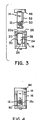
- Plug 14 is then moved from a position above receptacle 16, as shown in Fig. 3, to a lower position in channel 24 of receptacle 16, as shown in Fig. 4.
- Polarization keys 60 and 62 on plug 14 (Fig. 1) engage tracks 34 and 36, respectively, of receptacle 16 to provide a mating fit of plug 14 in channel 24 of receptacle 16.
- blade 20 is moved into slot 56.
- the cutting edge 20a of blade 20 passes through cable 12 to severe the same into two parts; one being held by subchannel 50a, and the other being held by subchannel 50b.
- the optical cable 12 is being supported on both sides of the cutting blade 20 by each sub- channel 50a and 50b.
- a more uniform termination end face 12c will be provided at the point of severing then is possible when supporting the fiber on only one side of the cutting blade.
- the cutting blade 20 is passed through slot 56 to severe cable 12
- the cable is prevented from bending or being deflected upon contact with the cutting blade 20 by the support of the cable on both sides of the blade.
- the cutting blade 20 will pass substantially perpendicularly through the cable both upon initial contact with the cable and throughout its movement through the cable. This results in a termination end face which will be substantially perpendicular to the cable 12. As the degree of perpendicularity of the end face to the fiber translate directly to improved optical transmission through the fiber, a termination end face which more closely approximates true perpendicularity will enhance optical transmission and permit transmission through an extended length of cable.
- the dimensional relationship between channel 50 of plug 14 and cable 12 is such that the cable is snugly fit in the channel 50 so that movement of the cable in channel 50 upon contact with the cutting blade 20 is minimized, thus further assuring a proper cut.
- the front end 42 of plug 14 may be removed from the remainder of termination subassembly 15. Front end 42 of plug 14 is only supported to the remainder of plug 14 by the small web of material at the floor 56a of slot 56. Further, this floor 56a has been scored by the cutting edge 20a of blade 20, thus the front end 42 of plug 14 is easily frangibly removed from the remainder of the plug 14. With the removal of front end 42 from the remainder of plug 14, a scrap end 13 of optical cable 12, which is supported in subchannel 50a, is also removed. Thus, the termination end face 12c of cable 12 will remain adjacent the front face of receptacle 16 (Fig.
- the termination sub-assembly 15 (Fig. 5), can then be inserted in termination housing 18.
- projection 48 on cantilevered lever 46 will deflect downwardly due to a forward bevel surface 48a thereon, to permit insertion of termination sub-assembly 15 in the chamber of termination housing 18.
- Projection 48 will then snap into upper opening 65 to secure termination sub-assembly 15 in housing 18.
- Removal of termination sub-assembly 15 may be facilitated by manually deflecting downwardly the extending edge of lever 46 to remove projection 48 from opening 65.
- the termination sub-assembly 15 can then be removed grasping on flaired end portion 40.
- the optical device supported in rear portion 64 of termination housing 18 is positionally located for alignment with the termination end face 12c of optical cable 12 upon insertion of the plug and receptacle combination 15 thereon.
- FIG. 6 An alternate embodiment of the present invention is shown in Fig. 6.
- Housing 70 is designed for captive receipt of each of termination sub-assemblies 15 on either side thereof in a manner substantially similar to that shown in Fig. 5.
- Appropriate cooperative keying and locking means may be included on the subassemblies 15 and/or housing 70 to facilitate interconnection.
- each of termination sub-assemblies 15 are inversely oriented for insertion on either end of housing 70.
- the termination end face held in each will be aligned for optical transmission therethrough.
- the present invention contemplates not only fiber termination with an LED, photo diode or other active element, but also contemplates use as a connector for a pair of optical fibers.
Landscapes
- Physics & Mathematics (AREA)
- General Physics & Mathematics (AREA)
- Optics & Photonics (AREA)
- Mechanical Coupling Of Light Guides (AREA)
- Light Guides In General And Applications Therefor (AREA)
Description
- This invention relates generally to a fiber optic termination device and pertains more particularly to a device for terminating optical fibers, wherin the fiber is severed upon termination in the device.
- Typical techniques used to terminate optical fibers, which are known in the prior art, employ a two step process of termination. The first step being fiber termination where fibers are stripped of the outer jacket and cut adjacent the end thereof to provide a fiber end face which typically must be polished or otherwise prepared to enhance optical transmission therethrough. The second step requires the mechanical assembly of the prepared fiber end in a housing of a termination device for registration with an optical device such as a light emitting diode or another optical fiber. There exists known techniques which combine both the fiber preparation step and mechanical assembly step in one operation. In commonly assigned U.S. Patent No. 4 422 715, issued December 27, 1983, entitled "Fiber Optic Connector Having Fiber Cutting Means" methods and apparatus are disclosed which provide a bridge between the separate fiber preparation and mechanical termination steps of previous devices, in one device.
- In the above-referenced patent there is disclosed a fiber optic connector assembly in which a cutting device and a termination device are supported in a fixed mutual relation in a common housing thereby bridging the two step approach. A companion housing provides for retentive engagement of the fiber. The housing are joinable in a first pre-cutting relation wherein the fiber spans the housings. The housings are mutually movable into a second relation effecting fiber cutting and are further mutually movable into a third relation providing registry of the termination device and the end face of the fiber resulting from the cutting. In the above-referenced Patent No. U.S.-A 4 422 715, a second device which provides such a bridge between fiber preparation and mechanical termination is disclosed. This device comprises a composite fiber cutting and terminating apparatus which includes a parent housing and an insert housing each adapted for mutual relative movement. The parent housing supports both an optical device and a cutting device. The insert housing supports the fiber. Upon movement of the insert housing into the parent housing, the fiber is retentively engaged by a support member of the insert housing. The fiber is moved into engagement with the cutting device, whereupon the fiber is cut to define an end face for termination with the optical device in the parent housing.
- As can be seen, the above two referenced devices each provide for cutting of the optical fiber to form a termination end face and immediate positioning of that end face with an optical device. There is no provision in either device for further preparation of the end face of the fiber once it is cut by the cutting device. Thus, end face polishing or chemical preparation is not typically possible nor desirable with these devices. While the end faces provided by the cutting blades of each of these devices is more than adequate for optical transmission through the fiber for short lengths, the end face provided by such devices, may not be suitable for optical transmission through extended fiber lengths.
- It is an object of the present invention to provide a termination device which would provide a superior termination end face on the fiber which is suitable for optical transmission through a fiber over extended lengths.
- According to the invention there is provided an apparatus for cutting an optical fiber with a cutting device and terminating said optical fiber, said apparatus comprising:
- a first housing supporting said cutting device; and
- a second housing for supporting said fiber and for insertion into said first housing; said second housing comprising a pair of integrally attached fiber accommodating portions each for accommodating a successive longitudinal extent of fiber, said pair of fiber accommodating portions defining a passage thereinbetween for accommodating said cutting device upon insertion of said second housing into said first housing to sever said fiber thereat and thereby defining a fiber termination surface adjacent said passage.
- A further object of the invention, in combination with a termination device, is to provide a fibre optic cutting and terminating device which would provide for both fiber preparation and mechanical termination in one operation.
- Accordingly, the invention further provides an assembly for providing optical transmission between an elongate optical fiber and an optical device comprising:
- a termination sub-assembly comprising:
- (a) a plug for supporting a longitudinal extent of said fiber at two spaced locations; and
- (b) a receptacle for receivably accommodating therein said plug; said receptacle further including cutting means for severing said fiber upon said reception of said plug in said receptacle at a location intermediate said two spaced locations to thereby form a fiber termination end face; and
- a termination device supporting said optical device, said termination device including a chamber for accommodating said termination sub-assembly therein and for placing said termination end face in optical connection with said optical device.
- By way of example, embodiments of an optical fiber termination device will now be described with reference to the accompanying drawings, in which:
- Fig. 1 shows in exploded perspective view the optical fiber termination device of the present invention including the optical fiber plug, receptacle and termination housing.
- Fig. 2 shows the optical fiber plug and receptacle sub-assembly of Fig. 1 with the optical fiber supported in the fiber plug.
- Fig. 3 is a side view of the plug and receptacle sub-assembly of Fig. 2.
- Fig. 4 shows the optical fiber plug of Fig. 2 inserted in the fiber receptacle, with the front portion of the fiber plug removed.
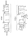
- Fig. 5 is a side view of the plug and receptacle sub-assembly including the terminated fiber, shown disassembled from the termination housing.
- Fig. 6 shows an alternate embodiment of the present invention wherein a pair of plug and receptacle sub-assemblies are shown supported in a central sleeve for connecting two optical fibers.
- Referring to Fig. 1, an
apparatus 10 for termination of anoptical fiber 12 is shown.Apparatus 10 includes a first housing orplug 14 for accommodating an optical fiber, a second housing orreceptacle 16 for accommodatingplug 14 and atermination device 18 for supporting an optical element (not shown), such as an LED, photo diode, optical fiber or the like. - Fiber
optic cable 12 is of conventional construction typically including aplastic fiber core 12a surrounded by outerplastic jacket 12b. In the present illustrative embodiment,plastic fiber core 12a is shown, however, the present invention contemplates use of glass fibers as well as plastic. Each ofelements - Referring additionally to Figs 2 and 3, receptacle
elongate blade 20, having a cutting edge 20a. Theblade 20 is supported at the upper end ofreceptacle 16 and is staked or otherwise suitably secured inslots 22 ofreceptacle 16.Receptacle 16 includes a centrallongitudinal channel 24 which opens intoupper wall 26 ofreceptacle 16 and is bounded by anarcuate floor 28 andside walls Side walls detent tracks side wall side wall 32 to provide key alignment forplug 14 which is inserted intochannel 24, as will be described in greater detail hereinbelow.Receptacle 16 further includes a flairedrearward end portion 40 which facilitates insertion and removal ofreceptacle 16 intermination housing 18, which also will be described in further detail hereinbelow. - Fiber
optic plug 14 is an elongate member having afirst end portion 42 for insertion toward theforward portion 21 ofreceptacle 16 and arear portion 44 for insertion adjacent the rearward flairedportion 40 ofreceptacle 16.Plug 14 further includes acantilevered lever 46 which extends from the upperrearward portion 44 and serves as a deflectable latch to secure theplug 14 andreceptacle 16 intermination housing 18. Aprojection 48 onlever 46 is insertable into an aligned opening intermination housing 18 to lock theplug 14 andreceptacle 16 in proper alignment intermination housing 18.Plug 14 further includes anelongate channel 50, extending longitudinally therealong. Channel 50 is generally a C-shaped channel opening intosidewall 52 ofplug 14.Plug 14 is divided between itsfront end 42 and rearwardend 44 by atransverse slot 56 which extends from itsfloor 56a, just below theupper surface 58 ofplug 14 and opens intolower surface 59 thereof. In addition to dividingplug 14,slot 56 also divideschannel 50 into two subchannels,forward sub-channel 50a and rearwardsubchannel 50b.Slot 56 accommodates for slidablepassage therethrough blade 20 ofreceptacle 16 upon insertion ofplug 14 intochannel 24. As shown in Fig. 2,optical fiber 12 is held inchannel 50 ofplug 14 so that a portion offiber 12 is supported in both forward sub-channel 50a and rearwardsubchannel 50b. Thus, upon insertion ofplug 14 intoreceptacle 16 as will be described further hereinafter,blade 20 and upper cutting edge 20a will severeoptical cable 12 at its locationadjacent slot 56, thereby forming atermination end face 12c (Fig. 4) onoptical fiber 12. The cutting edge 20a ofblade 20 will contact thefloor 56a to slightly score the same, weakening the junction betweenforward portion 42 and rearwardportion 44 ofplug 14. When positioned in the heretofore described interfitting position,plug 14 andreceptacle 16 form atermination sub-assembly 15 which supports a terminal end offiber 12. As will be described hereinbelow,forward portion 42 ofplug 14 can be frangably removed at the scoredfloor 56a ofslot 56 from termination sub-assembly 15 (Fig. 5). - As shown in Figs. 1 and 5,
termination housing 18 is generally a rectangular member having a centralopen chamber 60 which is dimensioned to accommodatetermination sub-assembly 15 withforward end 42 ofplug 14 frangably removed. Arearward portion 62 oftermination housing 18 supports therein an optical device (not shown) for optical registry with thetermination end face 12c ofoptical fiber 12. - Having described the individual elements of
connection apparatus 10, its operation and the interconnection of its various elements may now be described with reference to Figs. 1 through 5. -
Optical cable 12 is placed inchannel 50 ofplug 14 as shown in Fig. 2. The engagement ofplug 14 withreceptacle 16 will terminatecable 12 thereby providing afiber end face 12c.Cable 12 needs no special preparation prior to its insertion intoplug 14. The cable is inserted inchannel 50 so that an extent ofcable 12 extends beyond each longitudinal edge ofplug 14.Plug 14 is then moved from a position abovereceptacle 16, as shown in Fig. 3, to a lower position inchannel 24 ofreceptacle 16, as shown in Fig. 4.Polarization keys tracks receptacle 16 to provide a mating fit ofplug 14 inchannel 24 ofreceptacle 16. As the plug passes intochannel 24,blade 20 is moved intoslot 56. The cutting edge 20a ofblade 20 passes throughcable 12 to severe the same into two parts; one being held bysubchannel 50a, and the other being held bysubchannel 50b. During cutting, theoptical cable 12 is being supported on both sides of thecutting blade 20 by each sub-channel termination end face 12c will be provided at the point of severing then is possible when supporting the fiber on only one side of the cutting blade. As thecutting blade 20 is passed throughslot 56 tosevere cable 12, the cable is prevented from bending or being deflected upon contact with thecutting blade 20 by the support of the cable on both sides of the blade. Thus, thecutting blade 20 will pass substantially perpendicularly through the cable both upon initial contact with the cable and throughout its movement through the cable. This results in a termination end face which will be substantially perpendicular to thecable 12. As the degree of perpendicularity of the end face to the fiber translate directly to improved optical transmission through the fiber, a termination end face which more closely approximates true perpendicularity will enhance optical transmission and permit transmission through an extended length of cable. The dimensional relationship betweenchannel 50 ofplug 14 andcable 12 is such that the cable is snugly fit in thechannel 50 so that movement of the cable inchannel 50 upon contact with thecutting blade 20 is minimized, thus further assuring a proper cut. - Referring now to Figs. 4 and 5, once the
plug 14 is inserted intoreceptacle 16 andcable 12 is severed to formtermination end face 12c, thefront end 42 ofplug 14 may be removed from the remainder oftermination subassembly 15.Front end 42 ofplug 14 is only supported to the remainder ofplug 14 by the small web of material at thefloor 56a ofslot 56. Further, thisfloor 56a has been scored by the cutting edge 20a ofblade 20, thus thefront end 42 ofplug 14 is easily frangibly removed from the remainder of theplug 14. With the removal offront end 42 from the remainder ofplug 14, ascrap end 13 ofoptical cable 12, which is supported insubchannel 50a, is also removed. Thus, thetermination end face 12c ofcable 12 will remain adjacent the front face of receptacle 16 (Fig. 4). The termination sub-assembly 15 (Fig. 5), can then be inserted intermination housing 18. Upon insertion,projection 48 oncantilevered lever 46 will deflect downwardly due to aforward bevel surface 48a thereon, to permit insertion oftermination sub-assembly 15 in the chamber oftermination housing 18.Projection 48 will then snap intoupper opening 65 to securetermination sub-assembly 15 inhousing 18. Removal oftermination sub-assembly 15 may be facilitated by manually deflecting downwardly the extending edge oflever 46 to removeprojection 48 from opening 65. Thetermination sub-assembly 15 can then be removed grasping onflaired end portion 40. - The optical device supported in rear portion 64 of
termination housing 18 is positionally located for alignment with thetermination end face 12c ofoptical cable 12 upon insertion of the plug andreceptacle combination 15 thereon. - An alternate embodiment of the present invention is shown in Fig. 6. A pair of
termination sub-assemblies 15, which are formed in identical manner as above-described, are disposed on either side of hollowrectangular housing 70.Housing 70 is designed for captive receipt of each oftermination sub-assemblies 15 on either side thereof in a manner substantially similar to that shown in Fig. 5. Appropriate cooperative keying and locking means may be included on thesubassemblies 15 and/orhousing 70 to facilitate interconnection. As can be seen in Fig. 6, each oftermination sub-assemblies 15 are inversely oriented for insertion on either end ofhousing 70. Thus, upon a full insertion of eachtermination sub-assembly 15, the termination end face held in each will be aligned for optical transmission therethrough. Thus, the present invention contemplates not only fiber termination with an LED, photo diode or other active element, but also contemplates use as a connector for a pair of optical fibers. - Various changes may be made to the foregoing without departing from the scope of the claims.
Claims (10)
Applications Claiming Priority (2)
| Application Number | Priority Date | Filing Date | Title |
|---|---|---|---|
| US06/694,353 US4953940A (en) | 1985-01-24 | 1985-01-24 | Optical fiber termination device having cutting means |
| US694353 | 1996-08-08 |
Publications (3)
| Publication Number | Publication Date |
|---|---|
| EP0189323A2 EP0189323A2 (en) | 1986-07-30 |
| EP0189323A3 EP0189323A3 (en) | 1988-08-10 |
| EP0189323B1 true EP0189323B1 (en) | 1990-09-19 |
Family
ID=24788474
Family Applications (1)
| Application Number | Title | Priority Date | Filing Date |
|---|---|---|---|
| EP86300450A Expired EP0189323B1 (en) | 1985-01-24 | 1986-01-23 | Optical fiber termination device having cutting means |
Country Status (8)
| Country | Link |
|---|---|
| US (1) | US4953940A (en) |
| EP (1) | EP0189323B1 (en) |
| JP (1) | JPH0731283B2 (en) |
| AU (1) | AU561643B2 (en) |
| CA (1) | CA1279176C (en) |
| DE (1) | DE3674217D1 (en) |
| HK (1) | HK9292A (en) |
| SG (1) | SG98291G (en) |
Families Citing this family (13)
| Publication number | Priority date | Publication date | Assignee | Title |
|---|---|---|---|---|
| JPS61213811A (en) * | 1985-03-19 | 1986-09-22 | Sumitomo Electric Ind Ltd | Optical connector |
| DE3727092C1 (en) * | 1987-08-14 | 1988-11-10 | Wieland Elek Sche Ind Gmbh F | Fiber optic connection terminal |
| US5071219A (en) * | 1990-11-09 | 1991-12-10 | General Motors Corporation | Fiber optic connection system and method |
| US5894536A (en) * | 1997-02-14 | 1999-04-13 | Amphenol Corporation | In-line fiber optic splice protective device |
| CA2284882A1 (en) * | 1997-04-14 | 1998-10-22 | Larry R. Cox | Optical fiber holder and end-face preparation tool |
| US5813902A (en) * | 1997-04-14 | 1998-09-29 | Minnesota Mining And Manufacturing Company | Optical fiber end-face preparation and connector assembly |
| DE19732092C1 (en) * | 1997-07-03 | 1998-12-17 | Phoenix Contact Gmbh & Co | Terminal for fiber optic cables |
| US6636672B1 (en) * | 1999-07-07 | 2003-10-21 | Fitel Usa Corp | System comprising plastic optical fiber |
| US6379055B1 (en) * | 1999-12-22 | 2002-04-30 | Tyco Electronics Corporation | Fiber optic connector |
| US6816662B2 (en) * | 2002-09-19 | 2004-11-09 | 3M Innovative Properties Company | Article for cleaving and polishing optical fiber ends |
| DE112009002072B4 (en) | 2008-08-26 | 2019-05-16 | Avago Technologies International Sales Pte. Limited | Fiber optic cable connector with integrated cable distribution |
| EP2382499A2 (en) * | 2009-01-19 | 2011-11-02 | Corning Cable Systems LLC | Termination system for fiber optic connection |
| CN102565944B (en) * | 2012-01-16 | 2014-06-18 | 深圳日海通讯技术股份有限公司 | Adjustable fixed-length optical fiber cutting fixture |
Family Cites Families (11)
| Publication number | Priority date | Publication date | Assignee | Title |
|---|---|---|---|---|
| JPS5156684U (en) * | 1974-10-30 | 1976-05-04 | ||
| GB1577729A (en) * | 1976-09-25 | 1980-10-29 | Plessey Co Ltd | Coupling of optic-waveguide elements |
| GB1575341A (en) * | 1977-03-24 | 1980-09-17 | Green Precision Ind Ltd Lee | Method and apparatus for terminating optical fibres |
| FR2394823A1 (en) * | 1977-06-17 | 1979-01-12 | Noane Georges Le | EQUIPMENT AND ASSEMBLY PROCESS ON SITE AND ON CABLES FOR TRANSMISSION BY FIBER OPTICS OF PARTS ALLOWING INTERCHANGEABLE CONNECTIONS |
| JPS5567139U (en) * | 1978-10-30 | 1980-05-09 | ||
| US4326767A (en) * | 1979-03-12 | 1982-04-27 | Minnesota Mining And Manufacturing Company | Wire cutting electrical connector |
| US4444448A (en) * | 1980-01-14 | 1984-04-24 | Minnesota Mining And Manufacturing Company | Wire cutting electrical connector |
| US4422715A (en) * | 1981-06-22 | 1983-12-27 | Thomas & Betts Corporation | Fiber optic connector having fiber cutting means |
| JPS58117503A (en) * | 1981-12-29 | 1983-07-13 | アンプ インコーポレーテッド | Method and device for cutting optical fiber |
| US4582392A (en) * | 1982-04-16 | 1986-04-15 | Thomas & Betts Corporation | Fiber optic connector having operatable fiber retention means |
| SE456540B (en) * | 1982-04-16 | 1988-10-10 | Thomas & Betts Corp | A METHOD AND AN OPTICAL FIBER COUPLING FOR CUTTING AN OPTICAL FIBER AND INFORING THE CUTTED FIBER FOR COOPERATION WITH A CLUTCH DEVICE |
-
1985
- 1985-01-24 US US06/694,353 patent/US4953940A/en not_active Expired - Fee Related
-
1986
- 1986-01-21 AU AU52573/86A patent/AU561643B2/en not_active Ceased
- 1986-01-23 EP EP86300450A patent/EP0189323B1/en not_active Expired
- 1986-01-23 DE DE8686300450T patent/DE3674217D1/en not_active Expired - Fee Related
- 1986-01-24 JP JP61013563A patent/JPH0731283B2/en not_active Expired - Lifetime
- 1986-01-24 CA CA000500321A patent/CA1279176C/en not_active Expired - Lifetime
-
1991
- 1991-11-20 SG SG982/91A patent/SG98291G/en unknown
-
1992
- 1992-01-30 HK HK92/92A patent/HK9292A/en not_active IP Right Cessation
Also Published As
| Publication number | Publication date |
|---|---|
| DE3674217D1 (en) | 1990-10-25 |
| CA1279176C (en) | 1991-01-22 |
| US4953940A (en) | 1990-09-04 |
| JPH0731283B2 (en) | 1995-04-10 |
| JPS61198202A (en) | 1986-09-02 |
| AU5257386A (en) | 1986-07-31 |
| EP0189323A2 (en) | 1986-07-30 |
| AU561643B2 (en) | 1987-05-14 |
| EP0189323A3 (en) | 1988-08-10 |
| SG98291G (en) | 1992-01-17 |
| HK9292A (en) | 1992-01-31 |
Similar Documents
| Publication | Publication Date | Title |
|---|---|---|
| CA1194715A (en) | Fiber optic connector having fiber cutting means | |
| CA1279176C (en) | Optical fiber termination device having cutting means | |
| EP0484996B1 (en) | Optical fibre connector | |
| US5231685A (en) | Multi-way electro-optic connector assemblies and optical fiber ferrule assemblies therefor | |
| US5386487A (en) | Apparatus for maintaining plug assemblies of optical fiber connectors in a side by side relation with float therebetween | |
| US5118310A (en) | Central latch modular telephone connector | |
| CA1063398A (en) | Optical waveguide connector | |
| EP1278084B1 (en) | Optical connector | |
| EP1752805A2 (en) | Fiber optic connector | |
| US4917629A (en) | Electrical connector and termination method thereto | |
| DE3650519T2 (en) | Fiber optic connector | |
| EP1168017A2 (en) | Fiber optic connector | |
| US6230387B1 (en) | Optical fiber termination tool | |
| GB2239104A (en) | Multi-way electro-optic connectors | |
| EP0699355B1 (en) | Wire management adapters for terminating a cable | |
| JPH09204943A (en) | Guide plate for modular plug | |
| EP0899828A2 (en) | Communication plug | |
| KR100244417B1 (en) | Optical fiber cable connector | |
| EP0015291B1 (en) | Optical fiber connector | |
| EP0201748A2 (en) | Connector for a fiber optic cable | |
| EP1168016B1 (en) | Fiber optic connector | |
| US5742719A (en) | Fastening device for light waveguides | |
| US4582392A (en) | Fiber optic connector having operatable fiber retention means | |
| KR940018676A (en) | Fiber optic connectors | |
| GB2229588A (en) | Electrical connector |
Legal Events
| Date | Code | Title | Description |
|---|---|---|---|
| PUAI | Public reference made under article 153(3) epc to a published international application that has entered the european phase |
Free format text: ORIGINAL CODE: 0009012 |
|
| AK | Designated contracting states |
Kind code of ref document: A2 Designated state(s): BE CH DE FR GB IT LI NL SE |
|
| PUAL | Search report despatched |
Free format text: ORIGINAL CODE: 0009013 |
|
| RHK1 | Main classification (correction) |
Ipc: C03B 37/14 |
|
| AK | Designated contracting states |
Kind code of ref document: A3 Designated state(s): BE CH DE FR GB IT LI NL SE |
|
| 17P | Request for examination filed |
Effective date: 19880713 |
|
| 17Q | First examination report despatched |
Effective date: 19890712 |
|
| GRAA | (expected) grant |
Free format text: ORIGINAL CODE: 0009210 |
|
| AK | Designated contracting states |
Kind code of ref document: B1 Designated state(s): BE CH DE FR GB IT LI NL SE |
|
| REF | Corresponds to: |
Ref document number: 3674217 Country of ref document: DE Date of ref document: 19901025 |
|
| ITF | It: translation for a ep patent filed | ||
| PGFP | Annual fee paid to national office [announced via postgrant information from national office to epo] |
Ref country code: BE Payment date: 19901227 Year of fee payment: 6 |
|
| ET | Fr: translation filed | ||
| PLBE | No opposition filed within time limit |
Free format text: ORIGINAL CODE: 0009261 |
|
| STAA | Information on the status of an ep patent application or granted ep patent |
Free format text: STATUS: NO OPPOSITION FILED WITHIN TIME LIMIT |
|
| 26N | No opposition filed | ||
| PG25 | Lapsed in a contracting state [announced via postgrant information from national office to epo] |
Ref country code: BE Effective date: 19920131 |
|
| BERE | Be: lapsed |
Owner name: THOMAS & BETTS CORP. Effective date: 19920131 |
|
| ITTA | It: last paid annual fee | ||
| EAL | Se: european patent in force in sweden |
Ref document number: 86300450.3 |
|
| PGFP | Annual fee paid to national office [announced via postgrant information from national office to epo] |
Ref country code: FR Payment date: 20010117 Year of fee payment: 16 |
|
| PGFP | Annual fee paid to national office [announced via postgrant information from national office to epo] |
Ref country code: SE Payment date: 20010118 Year of fee payment: 16 Ref country code: GB Payment date: 20010118 Year of fee payment: 16 Ref country code: DE Payment date: 20010118 Year of fee payment: 16 |
|
| PGFP | Annual fee paid to national office [announced via postgrant information from national office to epo] |
Ref country code: CH Payment date: 20010122 Year of fee payment: 16 |
|
| PGFP | Annual fee paid to national office [announced via postgrant information from national office to epo] |
Ref country code: NL Payment date: 20010123 Year of fee payment: 16 |
|
| REG | Reference to a national code |
Ref country code: FR Ref legal event code: TP Ref country code: FR Ref legal event code: CA |
|
| REG | Reference to a national code |
Ref country code: GB Ref legal event code: IF02 |
|
| PG25 | Lapsed in a contracting state [announced via postgrant information from national office to epo] |
Ref country code: GB Free format text: LAPSE BECAUSE OF NON-PAYMENT OF DUE FEES Effective date: 20020123 |
|
| PG25 | Lapsed in a contracting state [announced via postgrant information from national office to epo] |
Ref country code: SE Free format text: LAPSE BECAUSE OF NON-PAYMENT OF DUE FEES Effective date: 20020124 |
|
| PG25 | Lapsed in a contracting state [announced via postgrant information from national office to epo] |
Ref country code: LI Free format text: LAPSE BECAUSE OF NON-PAYMENT OF DUE FEES Effective date: 20020131 Ref country code: CH Free format text: LAPSE BECAUSE OF NON-PAYMENT OF DUE FEES Effective date: 20020131 |
|
| PG25 | Lapsed in a contracting state [announced via postgrant information from national office to epo] |
Ref country code: NL Free format text: LAPSE BECAUSE OF NON-PAYMENT OF DUE FEES Effective date: 20020801 Ref country code: DE Free format text: LAPSE BECAUSE OF NON-PAYMENT OF DUE FEES Effective date: 20020801 |
|
| EUG | Se: european patent has lapsed |
Ref document number: 86300450.3 |
|
| GBPC | Gb: european patent ceased through non-payment of renewal fee |
Effective date: 20020123 |
|
| REG | Reference to a national code |
Ref country code: CH Ref legal event code: PL |
|
| PG25 | Lapsed in a contracting state [announced via postgrant information from national office to epo] |
Ref country code: FR Free format text: LAPSE BECAUSE OF NON-PAYMENT OF DUE FEES Effective date: 20020930 |
|
| NLV4 | Nl: lapsed or anulled due to non-payment of the annual fee |
Effective date: 20020801 |
|
| REG | Reference to a national code |
Ref country code: FR Ref legal event code: ST |
|
| PG25 | Lapsed in a contracting state [announced via postgrant information from national office to epo] |
Ref country code: IT Free format text: LAPSE BECAUSE OF NON-PAYMENT OF DUE FEES;WARNING: LAPSES OF ITALIAN PATENTS WITH EFFECTIVE DATE BEFORE 2007 MAY HAVE OCCURRED AT ANY TIME BEFORE 2007. THE CORRECT EFFECTIVE DATE MAY BE DIFFERENT FROM THE ONE RECORDED. Effective date: 20050123 |