EP0189180B1 - Ultrasonic bloodstream diagnostic apparatus with dual displays of velocity profiles and average flow velocity - Google Patents
Ultrasonic bloodstream diagnostic apparatus with dual displays of velocity profiles and average flow velocity Download PDFInfo
- Publication number
- EP0189180B1 EP0189180B1 EP86100789A EP86100789A EP0189180B1 EP 0189180 B1 EP0189180 B1 EP 0189180B1 EP 86100789 A EP86100789 A EP 86100789A EP 86100789 A EP86100789 A EP 86100789A EP 0189180 B1 EP0189180 B1 EP 0189180B1
- Authority
- EP
- European Patent Office
- Prior art keywords
- data
- bit
- output
- bits
- bit data
- Prior art date
- Legal status (The legal status is an assumption and is not a legal conclusion. Google has not performed a legal analysis and makes no representation as to the accuracy of the status listed.)
- Expired - Lifetime
Links
Images

Classifications
-
- G—PHYSICS
- G01—MEASURING; TESTING
- G01S—RADIO DIRECTION-FINDING; RADIO NAVIGATION; DETERMINING DISTANCE OR VELOCITY BY USE OF RADIO WAVES; LOCATING OR PRESENCE-DETECTING BY USE OF THE REFLECTION OR RERADIATION OF RADIO WAVES; ANALOGOUS ARRANGEMENTS USING OTHER WAVES
- G01S7/00—Details of systems according to groups G01S13/00, G01S15/00, G01S17/00
- G01S7/52—Details of systems according to groups G01S13/00, G01S15/00, G01S17/00 of systems according to group G01S15/00
- G01S7/52017—Details of systems according to groups G01S13/00, G01S15/00, G01S17/00 of systems according to group G01S15/00 particularly adapted to short-range imaging
- G01S7/52053—Display arrangements
- G01S7/52057—Cathode ray tube displays
- G01S7/52074—Composite displays, e.g. split-screen displays; Combination of multiple images or of images and alphanumeric tabular information
-
- G—PHYSICS
- G01—MEASURING; TESTING
- G01S—RADIO DIRECTION-FINDING; RADIO NAVIGATION; DETERMINING DISTANCE OR VELOCITY BY USE OF RADIO WAVES; LOCATING OR PRESENCE-DETECTING BY USE OF THE REFLECTION OR RERADIATION OF RADIO WAVES; ANALOGOUS ARRANGEMENTS USING OTHER WAVES
- G01S15/00—Systems using the reflection or reradiation of acoustic waves, e.g. sonar systems
- G01S15/88—Sonar systems specially adapted for specific applications
- G01S15/89—Sonar systems specially adapted for specific applications for mapping or imaging
- G01S15/8906—Short-range imaging systems; Acoustic microscope systems using pulse-echo techniques
- G01S15/8979—Combined Doppler and pulse-echo imaging systems
Definitions
- the present invention relates to a circuit for processing ultrasonic information for providing a simultaneous display of velocity profiles and a display of an average blood flow velocity with great accuracy, and more praticularly to an ultrasonic bloodstream diagnostic apparatus using this circuit for providing a display of velocity profiles as a function of time.
- an ultrasonic diagnostic apparatus comprises a quadrature phase detector which detects phase quadrature Doppler shifted signals. Those signals are digitized and fed to a digital frequency analyzer to obtain real and imaginary components of frequency spectrum. In order to determine the direction of the blood flow the frequency spectrum data is passed through a squaring circuit and a summing amplifier to obtain power spectrum data.
- the power spectrum data is then fed to a logarithmic processor to reduce the number of data bits representing the power spectrum to adapt the data to the dynamic range of B-scan monitor with respect to the size and cost of a scan converter and a digital-to-analog converter which are provided to process the power spectrum data into a form which is suitable for displaying.
- a logarithmic processor employs for deriving an average frequency of the power spectrum from the compressed power spectrum data for displaying an average flow velocity of bloodstream simultaneously with velocity profiles.
- the logarithmic compression of data bits results in an average frequency value which is inaccurate due to the nonlinearity of the logarithm.
- a circuit for processing ultrasonic information carrying Doppler frequency shifts which indicate the flow velocity of bloodstream comprising: a frequency analyzer for analyzing the frequencies of said received information, a power spectrum deriving means for deriving from the output of said frequency analyzer N-bit data representing the power spectrum of said Doppler frequency shifts, and an averaging means for deriving a signal representing the average frequency of said power spectrum, wherein said power spectrum deriving means derives said N-bit data by eliminating H higher bits and J lower bits from the output of said frequency analyzer, said N-Bit data are applied in parallel to a memory means comprised in a data compression means as address data, said data compression means converts said N-bit data to (M+L)-bit output data having M output bits and L output bits, wherein said M output bits respectively correspond to those of M bits in said N-bit data which are preceded by a series of K binary 0's, said M output bits having a binary 1 in the most significant bit position thereof, said L output bits represent
- an ultrasonic bloodstream diagnostic apparatus comprising: an ultrasonic probe for examining a patient's blood stream, a transmit/receive circuit means for exciting said probe to transmit ultrasonic energy from said probe into the patient body and receiving ultrasonic signals returning from tissues of said patient, a quadrature phase detector means for deriving phase quadrature signals from said received ultrasonic signals, an analog-to-digital converter means for digitising said phase quadrature signals, a frequency analyzer for analyzing the frequencies of said received information, a power spectrum deriving means for deriving from the output of said frequency analyzer N-bit data representing the power spectrum of said Doppler frequency shifts, and an averaging means for deriving a signal representing the average frequency of said power spectrum, wherein said power spectrum deriving means derives said N-bit data by eliminating H higher bits and J lower bits from the output of said frequency analyzer with a squaring means for squaring the output of said frequency analyzer, the squared value of the analyzer
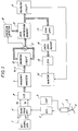
- FIG. 1 there is shown an ultrasonic bloodstream diagnostic apparatus according to the present invention. Illustrated at 1 is an ultrasonic probe placed in contact with the body of a patient 2. The probe 1 is excited by a transmit circuit 3 either in a continuous or pulsed mode to emit acoustic energy into a vessel 4 or the patient body to be examined. Acoustic energy reflecting from the vessel carries Doppler shift information representing the flow rate of the blood stream. The returning energy is detected by the same acoustic probe and sent to a quadrature phase detector 6 after amplifcation by a receive circuit 5. A reference signal generator 7 supplies reference phase quadrature signals to the phase detector 6 to generate output signals Va and Vb representing the Doppler frequency shifts.
- the doppler shift signals Va and Vb are supplied to an analog-to-digital converter 8, where each input signal is sampled and quantized to a 10-bit digital signal representing the flow rate of blood with a resolution of 210.
- the quantized signals are interleaved with each other to produce a multiplexed signal which is applied to a frequency analyzer 9 which analyzes the signal at prescribed frequency points of the spectrum, typically 128 points, using fast Fourier transformation technique, to detect the frequency spectrum of the Doppler shift. This frequency analysis is accomplished for a period of up to several tens of milliseconds to provide real-time display of the spectrum.
- the results of the frequency analysis are represented by a 16-bit digital signal Vr indicating the real part of the spectrum data and a 16-bit digital signal Vi indicating the imaginary part.
- the output signals Vr and Vi of the frequency analyzer 9 are multiplexed at the input of a squaring circuit 10 where each component is squared and demultiplexed from the other component.
- the square values of the real and imaginary components Vr and Vi are each represented by 16-bit data which are summed in an adder 11. As is known in the art, the summation of the squared real and imaginary parts generates a signal indicating the direction of blood flow at the output of the adder 11.
- the output of the adder 11 is represented by 16-bit data as obtained by the squaring circuit 10, it is necessary to reduce the number of bits to be processed at later stages. This reduction can be achieved by removing insignificant bits and compressing the remainder into a series of significant bits. This is accomplished by a data compression circuit 12 and an overflow detector 18.
- the data compression circuit 12 comprises a read-only memory having a capacity of, typically, 32 kilobits. The higher two bits and lower two bits of the 16-bit output of adder 11 are eliminated and the intermediate 12 bits are applied as address data to the memory 12. The lower two bits in the least significant positions are quantum noise. Thus, the elimination of a total of four bits results in a series of 12 significant bits which are applied in parallel to read-only memory 12 as address data.
- the memory 12 stores 8-bit data comprising 5-bits of "mantissa” and 3 bits of "index" which have been prepared in accordance with an algorithm shown in Figs. 2A to 2D.
- Each 8-bit datum is stored in a location addressible as a function of a particular value of the 12-bit input from the adder 11.
- the stored 8-bit datum comprises a sequence of 5 bits respectively corresponding to those of 5 bits in the 12-bit address datum which are preceded by a series of binary 0's.
- the 5-bit mantissa includes a binary 1 in the most significant bit position thereof and is appended by a 3-bit index which indicates the floating point of the mantissa which in turn corresponds to the least significant bit position of the mantissa with respect to the least significant bit position of the 12-bit address data structure.
- the least significant bit of the 5-bit mantissa corresponds to the least significant position of the 12-bit data and thus the floating point of the mantissa is at the zero-th decimal place in the floating point notation and is represented by a 3-bit datum "000".
- a 12-bit input "000111000000”, as shown in Fig. 2b addresses a memory location storing an 8-bit output datum "11100100", wherein the higher 5 bits "11100” indicates a mantissa and lower 3 bits "100” represents the fourth decimal place.
- an overflow detector 18 is connected to the 15-th bit position of the output of the adder 11 to detect the presence of a binary 1 in that bit position. Upon the detection of a binary 1 in the 15-th bit position, the overflow detector 18 generates a 12-bit address which causes the memory 12 to read out an 8-bit output data of the maximum value "11111111".
- the output of the data compression memory 12 is fed to an averaging circuit 17, or a microprocessor, which derives an average value of Doppler shift frequencies from the power spectrum and proceeds to detect the average flow velocity V according to the following equation: where, ⁇ f is the average frequency, fo is the frequency of the acoustic energy, C is the velocity of propagation of acoustic energy within tissues, and ⁇ represents the angle between the direction of acoustic energy and the vector of bloodstream.
- the average flow velocity data is displayed on a video monitor 16. Since the propagation velocity C is known as approximately 1,540 meters per second, the average flow velocity V is readily obtained by the angle ⁇ .
- the compressed data is also applied to a scan converter 13 where the scan format of the ultrasonic probe 1 is converted to the raster scan format of a video monitor 16.
- the compressed data is reconverted to the original 12-bit data and compressed to an 8-bit format according to logarithmic algorithm for adaptation to a digital-to-analog converter 15 and monitor 16.
- a data conversion circuit 14 which is formed by a read-only memory storing 8-bit data.
- the stored 8-bit data are derived from the reconversion of the 8-bit compressed data to the original 12-bit data and the logarithmic conversion of the latter to an 8-bit format.
- the 8-bit data are stored in locations addressible as a function of the particular value of 8-bit compressed datum.
- the 8-bit data read out of the memory 14 is converted to an analog signal by D/A converter 15 and displayed in a raster scan format by the monitor 16 simultaneously with the average flow rate supplied from the averaging circuit 17.
Landscapes
- Engineering & Computer Science (AREA)
- Physics & Mathematics (AREA)
- Radar, Positioning & Navigation (AREA)
- Remote Sensing (AREA)
- Acoustics & Sound (AREA)
- Computer Networks & Wireless Communication (AREA)
- General Physics & Mathematics (AREA)
- Ultra Sonic Daignosis Equipment (AREA)
Description
- The present invention relates to a circuit for processing ultrasonic information for providing a simultaneous display of velocity profiles and a display of an average blood flow velocity with great accuracy, and more praticularly to an ultrasonic bloodstream diagnostic apparatus using this circuit for providing a display of velocity profiles as a function of time.
- Ultrasonic Doppler shift imaging techniques have found extensive use in medical applications where it is desired to obtain the spectrum of bloodstream in a B-scan mode on a real time basis. In order to provide dual displays of velocity profiles and average flow velocity, an ultrasonic diagnostic apparatus comprises a quadrature phase detector which detects phase quadrature Doppler shifted signals. Those signals are digitized and fed to a digital frequency analyzer to obtain real and imaginary components of frequency spectrum. In order to determine the direction of the blood flow the frequency spectrum data is passed through a squaring circuit and a summing amplifier to obtain power spectrum data. The power spectrum data is then fed to a logarithmic processor to reduce the number of data bits representing the power spectrum to adapt the data to the dynamic range of B-scan monitor with respect to the size and cost of a scan converter and a digital-to-analog converter which are provided to process the power spectrum data into a form which is suitable for displaying. Recently developed techniques employ microprocessors for deriving an average frequency of the power spectrum from the compressed power spectrum data for displaying an average flow velocity of bloodstream simultaneously with velocity profiles. However, the logarithmic compression of data bits results in an average frequency value which is inaccurate due to the nonlinearity of the logarithm.
- From document US 4,305,063 the use of an automatic digital gain ranging system is known wherein read-in data are converted into a standard format which represents a certain range and the corresponding data in a 10-bit wide word.
- Furthermore, from pages 91 to 97 of the Encyclopedia of Computer Science, Van Nostrand Reinhold Company, 1978, some difficulties in connection with calculations by means of computers and the number systems used therefore as well as the conversion of the same are known. In this document different methods of calculation in case of fixed point numbers and floating point numbers are presented and explained in an exemplary manner.
- It is an object of the present invention to provide an ultrasonic bloodstream diagnostic apparatus and/or a circuit for processing ultrasonic information in such a way that an accurate measurement of average flow velocity can be achieved in an easy and fast way.
- This object can be achieved by a circuit for processing ultrasonic information carrying Doppler frequency shifts which indicate the flow velocity of bloodstream, comprising: a frequency analyzer for analyzing the frequencies of said received information,a power spectrum deriving means for deriving from the output of said frequency analyzer N-bit data representing the power spectrum of said Doppler frequency shifts, and an averaging means for deriving a signal representing the average frequency of said power spectrum, wherein said power spectrum deriving means derives said N-bit data by eliminating H higher bits and J lower bits from the output of said frequency analyzer, said N-Bit data are applied in parallel to a memory means comprised in a data compression means as address data, said data compression means converts said N-bit data to (M+L)-bit output data having M output bits and L output bits, wherein said M output bits respectively correspond to those of M bits in said N-bit data which are preceded by a series of K binary 0's, said M output bits having a binary 1 in the most significant bit position thereof, said L output bits represent the least significant bit position of said M output bits with respect to the least significant bit position of said N-bit data, K ranging from zero to N-M and (M+L) being smaller than N, a means for detecting a binary 1 in a predetermined one of said H higher bits for causing said memory means to generate (M+L)-bit data of maximum value, said averaging means derives said signal representing the average frequency of said power spectrum from said (M+L)-bit output data, and a data conversion means converts said (M+L)-bit output data into significant data to be displayed.
- Furthermore, this object can be achieved by an ultrasonic bloodstream diagnostic apparatus comprising: an ultrasonic probe for examining a patient's blood stream, a transmit/receive circuit means for exciting said probe to transmit ultrasonic energy from said probe into the patient body and receiving ultrasonic signals returning from tissues of said patient, a quadrature phase detector means for deriving phase quadrature signals from said received ultrasonic signals, an analog-to-digital converter means for digitising said phase quadrature signals, a frequency analyzer for analyzing the frequencies of said received information, a power spectrum deriving means for deriving from the output of said frequency analyzer N-bit data representing the power spectrum of said Doppler frequency shifts, and an averaging means for deriving a signal representing the average frequency of said power spectrum, wherein said power spectrum deriving means derives said N-bit data by eliminating H higher bits and J lower bits from the output of said frequency analyzer with a squaring means for squaring the output of said frequency analyzer, the squared value of the analyzer output being represented by N' bits which include said N-bit data plus said insignificant H higher bits in positions higher than said N-bit data and said insignificant L lower bits in positions lower than said N-bit data and with a summing means for summing the output from said squaring means and for generating said N-bit data, said N-Bit data are applied in parallel to a memory means comprised in a data compression means as address data, said data compression means converts said N-bit data to (M+L)-bit output data having M output bits and L output bits, wherein said M output bits respectively correspond to those of M bits in said N-bit data which are preceded by a series of K binary 0's, said M output bits having a
binary 1 in the most significant bit position thereof, said L output bits represent the least significant bit position of said M output bits with respect to the least significant bit position of said N-bit data, K ranging from zero to N-M and (M+L) being smaller than N, a means for detecting a binary 1 in a predetermined one of said H higher bits for causing said memory means to generate (M+L)-bit data of maximum value, said averaging means derives said signal representing the average frequency of said power spectrum from said (M+L)-bit output data and deriving therefrom a signal representing the average speed of the patient's blood stream, a data conversion means converts said (M+L)-bit output data into significant data to be displayed, and wherein said ultrasonic bloodstream diagnostic apparatus further comprises: a digital-to-analog converter means for converting said significant data into an analog signal, and a monitor means for providing a display of the analog signal in a raster scan format and a display of said average speed. - The present invention will be described in further detail with reference to the accompanying drawings, in which:
- Fig. 1 is a block diagram of an ultrasonic imaging apparatus according to a preferred embodiment of the present invention; and
- Figs. 2A to 2D are illustrations of data bits involved in the data compression memory of Fig. 1.
- Referring now to Fig. 1, there is shown an ultrasonic bloodstream diagnostic apparatus according to the present invention. Illustrated at 1 is an ultrasonic probe placed in contact with the body of a patient 2. The
probe 1 is excited by a transmit circuit 3 either in a continuous or pulsed mode to emit acoustic energy into a vessel 4 or the patient body to be examined. Acoustic energy reflecting from the vessel carries Doppler shift information representing the flow rate of the blood stream. The returning energy is detected by the same acoustic probe and sent to a quadrature phase detector 6 after amplifcation by a receive circuit 5. A reference signal generator 7 supplies reference phase quadrature signals to the phase detector 6 to generate output signals Va and Vb representing the Doppler frequency shifts. The doppler shift signals Va and Vb are supplied to an analog-to-digital converter 8, where each input signal is sampled and quantized to a 10-bit digital signal representing the flow rate of blood with a resolution of 2¹⁰. The quantized signals are interleaved with each other to produce a multiplexed signal which is applied to a frequency analyzer 9 which analyzes the signal at prescribed frequency points of the spectrum, typically 128 points, using fast Fourier transformation technique, to detect the frequency spectrum of the Doppler shift. This frequency analysis is accomplished for a period of up to several tens of milliseconds to provide real-time display of the spectrum. The results of the frequency analysis are represented by a 16-bit digital signal Vr indicating the real part of the spectrum data and a 16-bit digital signal Vi indicating the imaginary part. - The output signals Vr and Vi of the frequency analyzer 9 are multiplexed at the input of a
squaring circuit 10 where each component is squared and demultiplexed from the other component. The square values of the real and imaginary components Vr and Vi are each represented by 16-bit data which are summed in anadder 11. As is known in the art, the summation of the squared real and imaginary parts generates a signal indicating the direction of blood flow at the output of theadder 11. - Since the output of the
adder 11 is represented by 16-bit data as obtained by thesquaring circuit 10, it is necessary to reduce the number of bits to be processed at later stages. This reduction can be achieved by removing insignificant bits and compressing the remainder into a series of significant bits. This is accomplished by adata compression circuit 12 and anoverflow detector 18. In a preferred embodiment, thedata compression circuit 12 comprises a read-only memory having a capacity of, typically, 32 kilobits. The higher two bits and lower two bits of the 16-bit output ofadder 11 are eliminated and the intermediate 12 bits are applied as address data to thememory 12. The lower two bits in the least significant positions are quantum noise. Thus, the elimination of a total of four bits results in a series of 12 significant bits which are applied in parallel to read-only memory 12 as address data. - The
memory 12 stores 8-bit data comprising 5-bits of "mantissa" and 3 bits of "index" which have been prepared in accordance with an algorithm shown in Figs. 2A to 2D. Each 8-bit datum is stored in a location addressible as a function of a particular value of the 12-bit input from theadder 11. The stored 8-bit datum comprises a sequence of 5 bits respectively corresponding to those of 5 bits in the 12-bit address datum which are preceded by a series of binary 0's. The 5-bit mantissa includes a binary 1 in the most significant bit position thereof and is appended by a 3-bit index which indicates the floating point of the mantissa which in turn corresponds to the least significant bit position of the mantissa with respect to the least significant bit position of the 12-bit address data structure. - The data compression algorithm will be best understood by the following description given with reference to Figs. 2a to 2d. Assume that a 12-bit datum from
adder 11 is "000000011111" as shown at Fig. 2a, an 8-bit output datum "11111000" is read out of thememory 12. The higher 5 bits indicates a mantissa corresponding to the lower 5 binary 1's of the 12-bit input and the lower 3 bits indicates an index representing the floating point, or least significant bit position of the higher 5 bits with respect to the significant bit position of the input address data. In Fig. 2a, the least significant bit of the 5-bit mantissa corresponds to the least significant position of the 12-bit data and thus the floating point of the mantissa is at the zero-th decimal place in the floating point notation and is represented by a 3-bit datum "000". Likewise, a 12-bit input "000111000000", as shown in Fig. 2b, addresses a memory location storing an 8-bit output datum "11100100", wherein the higher 5 bits "11100" indicates a mantissa and lower 3 bits "100" represents the fourth decimal place. - Therefore, an 8-bit output datum of the same value "11111111" will be generated for a set of 12-bit inputs ranging from "111110000000" to "111111111111" as shown in Figs. 2c and 2d. This means that there is a maximum error of the lower seven bits "1111111". However, this error accounts for only about 3 percent of possible input bit combinations which is negligible for practical purposes.
- To compensate for errors which would be introduced by the elimination of the 15-th bit position of the adder output data, an
overflow detector 18 is connected to the 15-th bit position of the output of theadder 11 to detect the presence of a binary 1 in that bit position. Upon the detection of a binary 1 in the 15-th bit position, theoverflow detector 18 generates a 12-bit address which causes thememory 12 to read out an 8-bit output data of the maximum value "11111111". - The output of the
data compression memory 12 is fed to an averaging circuit 17, or a microprocessor, which derives an average value of Doppler shift frequencies from the power spectrum and proceeds to detect the average flow velocity V according to the following equation:
where, Δf is the average frequency, fo is the frequency of the acoustic energy, C is the velocity of propagation of acoustic energy within tissues, and ϑ represents the angle between the direction of acoustic energy and the vector of bloodstream. The average flow velocity data is displayed on avideo monitor 16. Since the propagation velocity C is known as approximately 1,540 meters per second, the average flow velocity V is readily obtained by the angle ϑ. - The compressed data is also applied to a
scan converter 13 where the scan format of theultrasonic probe 1 is converted to the raster scan format of avideo monitor 16. The compressed data is reconverted to the original 12-bit data and compressed to an 8-bit format according to logarithmic algorithm for adaptation to a digital-to-analog converter 15 and monitor 16. This is accomplished by adata conversion circuit 14 which is formed by a read-only memory storing 8-bit data. The stored 8-bit data are derived from the reconversion of the 8-bit compressed data to the original 12-bit data and the logarithmic conversion of the latter to an 8-bit format. The 8-bit data are stored in locations addressible as a function of the particular value of 8-bit compressed datum. The 8-bit data read out of thememory 14 is converted to an analog signal by D/A converter 15 and displayed in a raster scan format by themonitor 16 simultaneously with the average flow rate supplied from the averaging circuit 17.
Claims (7)
- A circuit for processing ultrasonic information carrying Doppler frequency shifts which indicate the flow velocity of bloodstream, comprising:
a frequency analyzer for analyzing the frequencies of said received information,
a power spectrum deriving means for deriving from the output of said frequency analyzer N-bit data representing the power spectrum of said Doppler frequency shifts, and
an averaging means for deriving a signal representing the average frequency of said power spectrum, wherein
said power spectrum deriving means derives said N-bit data by eliminating H higher bits and J lower bits from the output of said frequency analyzer,
said N-Bit data are applied in parallel to a memory means comprised in a data compression means as address data,
said data compression means converts said N-bit data to (M+L)-bit output data having M output bits and L output bits, wherein said M output bits respectively correspond to those of M bits in said N-bit data which are preceded by a series of K binary 0's, said M output bits having a binary 1 in the most significant bit position thereof, said L output bits represent the least significant bit position of said M output bits with respect to the least significant bit position of said N-bit data, K ranging from zero to N-M and (M+L) being smaller than N,
a means for detecting a binary 1 in a predetermined one of said H higher bits for causing said memory means to generate (M+L)-bit data of maximum value,
said averaging means derives said signal representing the average frequency of said power spectrum from said (M+L)-bit output data, and
a data conversion means converts said (M+L)-bit output data into significant data to be displayed. - A circuit according to claim 1, characterized in that said power spectrum deriving means comprises a squaring means for squaring the output of said frequency analyzer, the squared value of the analyzer output being represented by N' bits which include said N-bit data plus said insignificant H higher bits in positions higher than said N-bit data and said insignificant L lower bits in positions lower than said N-bit data.
- A circuit according to claim 2, characterized in that said power spectrum deriving means comprises a summing means for summing the output from said squaring means and for generating said N-bit data.
- An ultrasonic bloodstream diagnostic apparatus comprising:
an ultrasonic probe for examining a patient's blood stream,
a transmit/receive circuit means for exciting said probe to transmit ultrasonic energy from said probe into the patient body and receiving ultrasonic signals returning from tissues of said patient,
a quadrature phase detector means for deriving phase quadrature signals from said received ultrasonic signals,
an analog-to-digital converter means for digitizing said phase quadrature signals,
a frequency analyzer for analyzing the frequencies of said received information,
a power spectrum deriving means for deriving from the output of said frequency analyzer N-bit data representing the power spectrum of said Doppler frequency shifts, and
an averaging means for deriving a signal representing the average frequency of said power spectrum, wherein
said power spectrum deriving means derives said N-bit data by eliminating H higher bits and J lower bits from the output of said frequency analyzer with a squaring means for squaring the output of said frequency analyzer, the squared value of the analyzer output being represented by N' bits which include said N-bit data plus said insignificant H higher bits in positions higher than said N-bit data and said insignificant L lower bits in positions lower than said N-bit data and with a summing means for summing the output from said squaring means and for generating said N-bit data,
said N-Bit data are applied in parallel to a memory means comprised in a data compression means as address data,
said data compression means converts said N-bit data to (M+L)-bit output data having M output bits and L output bits, wherein said M output bits respectively correspond to those of M bits in said N-bit data which are preceded by a series of K binary 0's, said M output bits having a binary 1 in the most significant bit position thereof, said L output bits represent the least significant bit position of said M output bits with respect to the least significant bit position of said N-bit data, K ranging from zero to N-M and (M+L) being smaller than N,
a means for detecting a binary 1 in a predetermined one of said H higher bits for causing said memory means to generate (M+L)-bit data of maximum value,
said averaging means derives said signal representing the average frequency of said power spectrum from said (M+L)-bit output data and deriving therefrom a signal representing the average speed of the patient's blood stream,
a data conversion means converts said (M+L)-bit output data into significant data to be displayed, and
wherein said ultrasonic bloodstream diagnostic apparatus further comprises:
a digital-to-analog converter means for converting said significant data into an analog signal, and
a monitor means for providing a display of the analog signal in a raster scan format and a display of said average speed. - An ultrasonic bloodstream diagnostic apparatus according to claim 4, characterized in that said frequency analyzer provides fast fourier transformation on digital signals.
- An ultrasonic bloodstream diagnostic apparatus according to claim 4, characterized in that said data conversion means comprises a second memory means for storing data which correspond to a replica of said N-bit data which would be derived in correspondence to said (M+L)-bit output data, said replica being converted to the last-mentioned stored data according to a logarithmic function, the data in said second memory means being stored at locations which can be addressed as a function of said N-bit data.
- A circuit according to claim 1, characterized in that said data conversion means comprises a second memory means for storing data which correspond to a replica of said N-bit data which would be derived in correspondence to said (M+L)-bit output data, said replica being converted to the last-mentioned stored data according to a logarithmic function, the data in said second memory means being stored at locations which can be addressed as a function of said N-bit data.
Applications Claiming Priority (2)
| Application Number | Priority Date | Filing Date | Title |
|---|---|---|---|
| JP60010056A JPS61170442A (en) | 1985-01-23 | 1985-01-23 | Ultrasonic doppler blood flow apparatus |
| JP10056/85 | 1985-01-23 |
Publications (3)
| Publication Number | Publication Date |
|---|---|
| EP0189180A2 EP0189180A2 (en) | 1986-07-30 |
| EP0189180A3 EP0189180A3 (en) | 1989-01-25 |
| EP0189180B1 true EP0189180B1 (en) | 1993-12-08 |
Family
ID=11739729
Family Applications (1)
| Application Number | Title | Priority Date | Filing Date |
|---|---|---|---|
| EP86100789A Expired - Lifetime EP0189180B1 (en) | 1985-01-23 | 1986-01-22 | Ultrasonic bloodstream diagnostic apparatus with dual displays of velocity profiles and average flow velocity |
Country Status (4)
| Country | Link |
|---|---|
| US (1) | US4751929A (en) |
| EP (1) | EP0189180B1 (en) |
| JP (1) | JPS61170442A (en) |
| DE (1) | DE3689360T2 (en) |
Cited By (1)
| Publication number | Priority date | Publication date | Assignee | Title |
|---|---|---|---|---|
| CN102895001A (en) * | 2012-09-21 | 2013-01-30 | 飞依诺科技(苏州)有限公司 | Ultrasonic color blood flow imaging dynamic range compression processing method and system |
Families Citing this family (21)
| Publication number | Priority date | Publication date | Assignee | Title |
|---|---|---|---|---|
| US5020374A (en) * | 1989-11-17 | 1991-06-04 | Ads Environmental Services, Inc. | Velocity measurement system |
| US4888694A (en) * | 1987-10-28 | 1989-12-19 | Quantum Medical Systems, Inc. | Ultrasound imaging system for relatively low-velocity blood flow at relatively high frame rates |
| US4930513A (en) * | 1988-07-26 | 1990-06-05 | U.S. Philips Corporation | Two dimensional processing of pulsed Doppler signals |
| US5058594A (en) * | 1990-08-29 | 1991-10-22 | Quantum Medical Systems, Incorporated | Direct velocity estimator for ultrasound blood flow imaging |
| US5224482A (en) * | 1991-04-08 | 1993-07-06 | Kabushiki Kaisha Toshiba | Ultrasound high velocity flow correlation measurement using coded pulses |
| US5349960A (en) * | 1991-10-01 | 1994-09-27 | Olympus Optical Co., Ltd. | Ultrasonic diagnosis apparatus |
| JP3665423B2 (en) * | 1995-08-28 | 2005-06-29 | セイコーエプソン株式会社 | Fast Fourier transform computing device and fast Fourier transform computing device |
| EP1012627B1 (en) * | 1997-09-10 | 2002-10-23 | Riegl Laser Measurement Systems Gmbh | Optoelectronic measuring method and an optoelectronic measuring device |
| US6196972B1 (en) * | 1998-11-11 | 2001-03-06 | Spentech, Inc. | Doppler ultrasound method and apparatus for monitoring blood flow |
| US6344735B1 (en) * | 1999-04-07 | 2002-02-05 | Advantest Corporation | Spectrum analyzer and spectrum measuring method using the same |
| JP2003265468A (en) * | 2002-03-19 | 2003-09-24 | Ge Medical Systems Global Technology Co Llc | Diagnosis information generating device and ultrasonograph |
| US7128713B2 (en) * | 2003-07-10 | 2006-10-31 | Spentech, Inc. | Doppler ultrasound method and apparatus for monitoring blood flow and hemodynamics |
| US7771358B2 (en) * | 2005-05-20 | 2010-08-10 | Spentech, Inc. | System and method for grading microemboli monitored by a multi-gate doppler ultrasound system |
| US8162837B2 (en) * | 2005-06-13 | 2012-04-24 | Spentech, Inc. | Medical doppler ultrasound system for locating and tracking blood flow |
| CN100496409C (en) * | 2005-08-02 | 2009-06-10 | 深圳迈瑞生物医疗电子股份有限公司 | Automatic detection method of frequency spectrum Doppler blood flow velocity |
| US8157738B2 (en) * | 2009-06-02 | 2012-04-17 | Samplify Systems, Inc. | Ultrasound signal compression |
| US8317706B2 (en) * | 2009-06-29 | 2012-11-27 | White Eagle Sonic Technologies, Inc. | Post-beamforming compression in ultrasound systems |
| EP2538833A4 (en) * | 2010-02-08 | 2014-03-12 | Univ Oregon Health & Science | METHOD AND APPARATUS FOR ULTRASENSITIVE OPTICAL MICROANGIOGRAPHY |
| DE112015001709A5 (en) | 2014-06-05 | 2017-01-26 | Conti Temic Microelectronic Gmbh | Radar system with optimized storage of intermediate data |
| CN105286920B (en) * | 2015-11-05 | 2017-10-10 | 无锡祥生医学影像有限责任公司 | Ultrasound Doppler information self-adapting interference suppression method |
| DE102020007046B3 (en) * | 2020-11-18 | 2022-04-07 | Aaronia Ag | Spectrum analyzer, system and method for extracting data from a spectrum analyzer |
Family Cites Families (10)
| Publication number | Priority date | Publication date | Assignee | Title |
|---|---|---|---|---|
| US4305063A (en) * | 1977-03-04 | 1981-12-08 | Grumman Aerospace Corp. | Automatic digital gain ranging system |
| US4217909A (en) * | 1978-08-23 | 1980-08-19 | General Electric Company | Directional detection of blood velocities in an ultrasound system |
| JPS55143132A (en) * | 1979-04-26 | 1980-11-08 | Kuniyasu Furuhira | Measuring device for medical treatment |
| US4265126A (en) * | 1979-06-15 | 1981-05-05 | General Electric Company | Measurement of true blood velocity by an ultrasound system |
| FR2478321A1 (en) * | 1980-03-14 | 1981-09-18 | Bertin & Cie | SYSTEM FOR PROCESSING AN ACOUSTIC WIRE SPEED REMOTE SENSING SIGNAL |
| US4432031A (en) * | 1982-05-03 | 1984-02-14 | General Electric Company | Method for overcurrent protection |
| JPS5920820A (en) * | 1982-07-28 | 1984-02-02 | Aloka Co Ltd | Method and apparatus for forming ultrasonic wave image |
| JPS59103169A (en) * | 1982-12-03 | 1984-06-14 | Matsushita Electric Ind Co Ltd | Digital signal processor |
| US4558302A (en) * | 1983-06-20 | 1985-12-10 | Sperry Corporation | High speed data compression and decompression apparatus and method |
| US4583553A (en) * | 1983-11-15 | 1986-04-22 | Medicomp, Inc. | Ambulatory ECG analyzer and recorder |
-
1985
- 1985-01-23 JP JP60010056A patent/JPS61170442A/en active Pending
-
1986
- 1986-01-21 US US06/823,094 patent/US4751929A/en not_active Expired - Lifetime
- 1986-01-22 EP EP86100789A patent/EP0189180B1/en not_active Expired - Lifetime
- 1986-01-22 DE DE3689360T patent/DE3689360T2/en not_active Expired - Lifetime
Non-Patent Citations (1)
| Title |
|---|
| Encyclopedia of Computer Science, Van Nostrand Reinhold Company, 1978, pages 91-97 * |
Cited By (2)
| Publication number | Priority date | Publication date | Assignee | Title |
|---|---|---|---|---|
| CN102895001A (en) * | 2012-09-21 | 2013-01-30 | 飞依诺科技(苏州)有限公司 | Ultrasonic color blood flow imaging dynamic range compression processing method and system |
| CN102895001B (en) * | 2012-09-21 | 2014-07-23 | 飞依诺科技(苏州)有限公司 | Ultrasonic color blood flow imaging dynamic range compression processing method and system |
Also Published As
| Publication number | Publication date |
|---|---|
| US4751929A (en) | 1988-06-21 |
| DE3689360T2 (en) | 1994-06-30 |
| DE3689360D1 (en) | 1994-01-20 |
| JPS61170442A (en) | 1986-08-01 |
| EP0189180A3 (en) | 1989-01-25 |
| EP0189180A2 (en) | 1986-07-30 |
Similar Documents
| Publication | Publication Date | Title |
|---|---|---|
| EP0189180A2 (en) | Ultrasonic bloodstream diagnostic apparatus with dual displays of velocity profiles and average flow velocity | |
| US5005419A (en) | Method and apparatus for coherent imaging system | |
| US4324258A (en) | Ultrasonic doppler flowmeters | |
| US4809703A (en) | Ultrasonic doppler blood flow meter | |
| US4896674A (en) | Ultrasonic diagnosing system | |
| JP2738939B2 (en) | Doppler ultrasound equipment | |
| EP0150997B1 (en) | Measuring characteristics of an ultrasonic wave medium | |
| EP0228070B1 (en) | Ultrasonic doppler diagnostic apparatus | |
| JPH07191962A (en) | Correction circuit for floating point amplifier | |
| US5107466A (en) | Ultrasonic doppler flow meter | |
| EP0248623B1 (en) | Ultrasound scanning apparatus | |
| US5107840A (en) | Device for measuring and displaying of ultrasonic echography the flow rate of a blood flow and the dilation of the associated vessel | |
| JP2728183B2 (en) | Bandwidth sampling scheme for digital signal focusing in array-type imaging systems | |
| EP0214654B1 (en) | Ultrasonic device for measuring acceleration of moving reflective member | |
| US5168877A (en) | Ultrasonic diagnostic apparatus | |
| JPH0751134B2 (en) | Ultrasound diagnostic image processor | |
| US6045504A (en) | Method and apparatus for polynomial approximation of nonlinear operations in medical ultrasound imaging | |
| JP2002000605A (en) | Ultrasonic receiver and receiving method | |
| EP0512837B1 (en) | Ultrasonic doppler imaging apparatus | |
| JPS6096232A (en) | Ultrasonic blood flow measuring apparatus | |
| JPH06273198A (en) | Wave characteristic extractor | |
| EP0626763B1 (en) | Method and apparatus for converting an analog signal to a digital floating-point number and a digital floating-pont number to an analog signal | |
| JP3207579B2 (en) | Radar equipment | |
| JPH08322841A (en) | Ultrasonic Doppler blood flow meter | |
| JP2563656B2 (en) | Ultrasonic Doppler imaging device |
Legal Events
| Date | Code | Title | Description |
|---|---|---|---|
| PUAI | Public reference made under article 153(3) epc to a published international application that has entered the european phase |
Free format text: ORIGINAL CODE: 0009012 |
|
| AK | Designated contracting states |
Kind code of ref document: A2 Designated state(s): DE FR GB |
|
| PUAL | Search report despatched |
Free format text: ORIGINAL CODE: 0009013 |
|
| AK | Designated contracting states |
Kind code of ref document: A3 Designated state(s): DE FR GB |
|
| 17P | Request for examination filed |
Effective date: 19890412 |
|
| 17Q | First examination report despatched |
Effective date: 19901115 |
|
| GRAA | (expected) grant |
Free format text: ORIGINAL CODE: 0009210 |
|
| AK | Designated contracting states |
Kind code of ref document: B1 Designated state(s): DE FR GB |
|
| ET | Fr: translation filed | ||
| REF | Corresponds to: |
Ref document number: 3689360 Country of ref document: DE Date of ref document: 19940120 |
|
| PLBE | No opposition filed within time limit |
Free format text: ORIGINAL CODE: 0009261 |
|
| STAA | Information on the status of an ep patent application or granted ep patent |
Free format text: STATUS: NO OPPOSITION FILED WITHIN TIME LIMIT |
|
| 26N | No opposition filed | ||
| REG | Reference to a national code |
Ref country code: GB Ref legal event code: IF02 |
|
| PGFP | Annual fee paid to national office [announced via postgrant information from national office to epo] |
Ref country code: FR Payment date: 20050110 Year of fee payment: 20 |
|
| PGFP | Annual fee paid to national office [announced via postgrant information from national office to epo] |
Ref country code: GB Payment date: 20050119 Year of fee payment: 20 |
|
| PGFP | Annual fee paid to national office [announced via postgrant information from national office to epo] |
Ref country code: DE Payment date: 20050120 Year of fee payment: 20 |
|
| PG25 | Lapsed in a contracting state [announced via postgrant information from national office to epo] |
Ref country code: GB Free format text: LAPSE BECAUSE OF EXPIRATION OF PROTECTION Effective date: 20060121 |
|
| REG | Reference to a national code |
Ref country code: GB Ref legal event code: PE20 |