EP0188140A1 - Oil seal for a rotating shaft - Google Patents
Oil seal for a rotating shaft Download PDFInfo
- Publication number
- EP0188140A1 EP0188140A1 EP85402281A EP85402281A EP0188140A1 EP 0188140 A1 EP0188140 A1 EP 0188140A1 EP 85402281 A EP85402281 A EP 85402281A EP 85402281 A EP85402281 A EP 85402281A EP 0188140 A1 EP0188140 A1 EP 0188140A1
- Authority
- EP
- European Patent Office
- Prior art keywords
- ring
- lip
- shaft
- seal
- rotating shaft
- Prior art date
- Legal status (The legal status is an assumption and is not a legal conclusion. Google has not performed a legal analysis and makes no representation as to the accuracy of the status listed.)
- Granted
Links
Images
Classifications
-
- B—PERFORMING OPERATIONS; TRANSPORTING
- B25—HAND TOOLS; PORTABLE POWER-DRIVEN TOOLS; MANIPULATORS
- B25B—TOOLS OR BENCH DEVICES NOT OTHERWISE PROVIDED FOR, FOR FASTENING, CONNECTING, DISENGAGING OR HOLDING
- B25B27/00—Hand tools, specially adapted for fitting together or separating parts or objects whether or not involving some deformation, not otherwise provided for
- B25B27/0028—Tools for removing or installing seals
-
- F—MECHANICAL ENGINEERING; LIGHTING; HEATING; WEAPONS; BLASTING
- F16—ENGINEERING ELEMENTS AND UNITS; GENERAL MEASURES FOR PRODUCING AND MAINTAINING EFFECTIVE FUNCTIONING OF MACHINES OR INSTALLATIONS; THERMAL INSULATION IN GENERAL
- F16J—PISTONS; CYLINDERS; SEALINGS
- F16J15/00—Sealings
- F16J15/16—Sealings between relatively-moving surfaces
- F16J15/32—Sealings between relatively-moving surfaces with elastic sealings, e.g. O-rings
- F16J15/3268—Mounting of sealing rings
Definitions
- the present invention relates to a gasket. lip for rotating shaft, of the type comprising an external peripheral fixing part, intended to be introduced into a housing of a fixed part, and a radially internal lip connected to said peripheral part and of which a sealing edge is intended to come in contact with elastic support at the periphery of a rotating shaft, to ensure the seal between this shaft and said fixed part.
- the object of the present invention is to provide this type of seal with improvements capable of eliminating the defects which may affect them by the very fact of the conditions in which the operations for mounting the seal on the shaft or of the shaft take place. in the joint.
- the aforementioned lip can in fact be cut or otherwise deteriorated by the passage of a sharp edge of the shaft (due to grooves, holes, chamfers, etc.), and can no longer then ensure perfectly its sealing function.
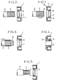
- Figure 1 shows in axial section a joint 1 of the general type concerned by the present invention, assumed to be subject to a fixed part (not shown), but to which joint the improvements of the invention have not been made, as well as a splined shaft end 2, intended to be engaged in the joint, the splines of the shaft being referenced in 3, and a chamfer in 4.
- the extraction can be done either axially or radially after cutting the ring in half.
- a joint of the general type defined at the start will, in accordance with the invention, be essentially characterized in that it comprises in front of said lip, having regard to the direction of the relative axial displacement of the shaft with respect to the joint during mounting operations, a protective and self-centering ring made of a relatively rigid but deformable material, the edge of the radially inner lip of this ring having in the free state a diameter less than that present , also in the free state, said sealing edge.
- This self-centering ring being in front of the sealing edge will protect it from any deterioration by guiding and centering the shaft perfectly during assembly.
- this ring will have the great advantage of not needing to be removed, since it will not interfere with the operation of the seal or the rotation of the shaft.
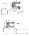
- FIGS. 6 and 7 the protective and self-centering ring has been referenced at 13.
- the diameter D1 of the edge 14 of the radially inner lip 15 of this ring is less than the diameter D2 of the sealing edge 7 of the seal, whereby, during the introduction of the grooved part 3, the shaft does not risk damaging said lip 7, being perfectly guided and self-centered by the lip 15.
- the external peripheral part 16 of the ring 13 is retained axially, with a minimum of friction, in a cage 17, delimited by a flange 18, of said external peripheral fixing part. 5 of the seal 1.
- the rim 18 can cooperate with a peripheral rib 21 of the ring.
- the lip 15 can, after mounting, serve as a deflector vis-à-vis external impurities, thus reinforcing the role of the conventional anti-dust lip 19 of the seal 1.
- the material constituting the ring 13 will, as indicated above, be relatively rigid, to correctly fulfill its guiding role, and must also have good temperature resistance, as well as a coefficient of friction as low as possible vis-à-vis - screw of the elastomer constituting the seal 1, and of course good wear resistance.
- Polyethylene or the like may be used for this purpose for the ring 13, the seal 1 being made of any suitable material, for example polyacrylate.
- the ring 13 (or the seal) carries an abutment surface 20, which can moreover be coated a layer of material further reducing friction.
- the ring 13 can be made more rigid by adding a metallic internal frame (not shown).
Abstract
Description
La présente invention concerne un joint d'étanchéité à. lèvre pour arbre tournant, du type comportant une partie périphérique extérieure de fixation, destinée à être introduite dans un logement d'une partie fixe, et une lèvre radialement intérieure reliée à ladite partie périphérique et dont une arête d'étanchéité est destinée à venir en contact avec appui élastique à la périphérie d'un arbre tournant, pour assurer l'étanchéité entre cet arbre et ladite partie fixe.The present invention relates to a gasket. lip for rotating shaft, of the type comprising an external peripheral fixing part, intended to be introduced into a housing of a fixed part, and a radially internal lip connected to said peripheral part and of which a sealing edge is intended to come in contact with elastic support at the periphery of a rotating shaft, to ensure the seal between this shaft and said fixed part.
Le but de la présente invention est d'apporter à ce type de joints des perfectionnements propres à éliminer les défauts qui peuvent les affecter du fait même des conditions dans lesquelles se déroulent les opérations de montage du joint sur l'arbre ou de l'arbre dans le joint.The object of the present invention is to provide this type of seal with improvements capable of eliminating the defects which may affect them by the very fact of the conditions in which the operations for mounting the seal on the shaft or of the shaft take place. in the joint.
La lèvre précitée peut en effet être coupée ou autrement détériorée au passage d'une arête vive de l'arbre (du fait de cannelures, trous, chanfreins,etc.), et ne peut plus alors assurer parfaitement sa fonction d'étanchéité.The aforementioned lip can in fact be cut or otherwise deteriorated by the passage of a sharp edge of the shaft (due to grooves, holes, chamfers, etc.), and can no longer then ensure perfectly its sealing function.
La figure 1 montre en coupe axiale un joint 1 du type général concerné par la présente invention, supposé assujetti à une partie fixe (non représentée), mais auquel joint les perfectionnements de l'invention n'ont pas été apportés, ainsi qu'un bout d'arbre cannelé 2, destiné à être engagé dans le joint, les cannelures de l'arbre étant référencées en 3, et un chanfrein en 4.Figure 1 shows in axial section a joint 1 of the general type concerned by the present invention, assumed to be subject to a fixed part (not shown), but to which joint the improvements of the invention have not been made, as well as a
Sur les différentes figures, on a pris partout les mêmes références pour désigner les mêmes parties ou éléments des joints connus ou du joint conforme à la présente invention :
- - 5 désigne la partie périphérique extérieure de fixation, destinée à être introduite dans un logement de la partie fixe précitée ;
- - 6 désigne la lèvre radialement intérieure, faisant suite à la
partie 5 ; - - 7 désigne l'arête d'étanchéité de la lèvre, destinée à venir élastiquement en contact avec la partie lisse de l'arbre 2 et, ainsi, à assurer l'étanchéité entre l'arbre et ladite partie fixe ;
- - 8 désigne une armature métallique interne ; et
- - 9 une bague élastique.
- - 5 designates the outer peripheral fixing part, intended to be introduced into a housing of the above-mentioned fixed part;
- - 6 designates the radially inner lip, following
part 5; - - 7 denotes the sealing edge of the lip, intended to come elastically into contact with the smooth part of the
shaft 2 and, thus, to ensure the seal between the shaft and said fixed part; - - 8 denotes an internal metal frame; and
- - 9 an elastic ring.
Ceci étant, on voit sur la figure 1 qu'avec ce type de joint connu la lèvre 7 risque d'être blessée par le chanfrein 4 et par les arêtes des cannelures 3 lors de l'introduction, dans le sens de la flèche, de l'arbre 2 dans le joint 1.That said, it can be seen in FIG. 1 that with this type of known seal the lip 7 risks being injured by the
Dans le cas de la figure 2, l'arbre 2 étant supposé fixe, on voit qu'il y a en outre un risque de retournement de la lèvre 6 lors de l'engagement du joint 1 sur l'arbre.In the case of FIG. 2, the
Pour remédier à ces inconvénients, on a envisagé d'emmancher un embout de protection arrondi à surface polie 10 en bout d'arbre, pour masquer son extrémité ainsi que les cannelures 3 (voir figure 3). Il faut cependant que cet embout puisse être retiré lorsque le joint est en place, ce qui est contraignant.To overcome these drawbacks, consideration has been given to fitting a rounded protective end piece with a polished
De plus, sur les chaînes de montage, le même embout est utilisé des milliers de fois et peut tomber. L'empreinte des chocs et les copeaux qui s'y collent peuvent alors à leur tour endommager l'arête d'étanchéité 7 du joint 1 lors du montage.In addition, on assembly lines, the same tip is used thousands of times and can fall off. The impact imprint and the chips that stick to it can then in turn damage the sealing edge 7 of the seal 1 during assembly.
On peut encore envisager (figure 4) de livrer chaque joint 1 avec une bague de protection en matière plastique dont le tube 11 a un diamètre supérieur à celui de l'arbre 2. On voit que la collerette 12 de la bague n'empêche pas le montage du joint 1 dans son logement ; elle permet à la bague d'être extraite après montage du joint 1 sur l'arbre 2.We can also consider (Figure 4) to deliver each joint 1 with a protective plastic ring whose
L'extraction peut se faire soit axialement, soit radialement après coupure de la bague en deux.The extraction can be done either axially or radially after cutting the ring in half.
Toutefois, une telle bague n'est pas toujours très facile à retirer et le risque d'oublier son extraction n'est pas négligeable, surtout lors de montages effectués en série.However, such a ring is not always very easy to remove and the risk of forgetting its extraction is not negligible, especially during assemblies carried out in series.
Selon encore une autre solution connue, on essaie de mettre à profit le fait, fréquent, que l'extrémité cannelée de l'arbre 2 est d'un diamètre nettement inférieur à celui de la partie lisse de l'arbre (figure 5). Cette caractéristique, cependant, est insuffisante pour éliminer tout risque de coupure de l'arête d'étanchéité 7 lors du montage, l'arbre n'étant pas assuré d'être correctement guidé.According to yet another known solution, we try to take advantage of the frequent fact that the grooved end of the
Pour remédier à ces divers inconvénients de la technique antérieure, un joint du type général défini au début sera, conformément à l'invention, essentiellement caractérisé en ce qu'il comporte en avant de ladite lèvre, eu égard au sens du déplacement axial relatif de l'arbre par rapport au joint lors des opérations de montage, une bague protectrice et autocentreuse en une matière relativement rigide mais déformable, l'arête de la lèvre radialement intérieure de cette bague ayant à l'état libre un diamètre inférieur à celui que présente, également à l'état libre, ladite arête d'étanchéité.To remedy these various drawbacks of the prior art, a joint of the general type defined at the start will, in accordance with the invention, be essentially characterized in that it comprises in front of said lip, having regard to the direction of the relative axial displacement of the shaft with respect to the joint during mounting operations, a protective and self-centering ring made of a relatively rigid but deformable material, the edge of the radially inner lip of this ring having in the free state a diameter less than that present , also in the free state, said sealing edge.
Cette bague autocentreuse étant devant l'arête d'étanchéité la protégera de toute détérioration en guidant et en centrant parfaitement l'arbre lors du montage. De plus, cette bague présentera le grand avantage de n'avoir pas besoin d'être retirée, car elle ne gênera ni le fonctionnement du joint ni la rotation de l'arbre.This self-centering ring being in front of the sealing edge will protect it from any deterioration by guiding and centering the shaft perfectly during assembly. In addition, this ring will have the great advantage of not needing to be removed, since it will not interfere with the operation of the seal or the rotation of the shaft.
Un mode d'exécution de l'invention va maintenant être décrit, à titre d'exemple nullement limitatif, avec référence aux figures du dessin annexé dans lequel :
- - la figure 6 est une demi-coupe axiale d'un joint conforme à l'invention avant introduction de la partie lisse d'un
arbre 2 et - - la figure 7 est une vue semblable à celle de la figure 6, après montage.
- - Figure 6 is an axial half-section of a seal according to the invention before introduction of the smooth part of a
tree 2 and - - Figure 7 is a view similar to that of Figure 6, after assembly.
Sur les figures 6 et 7, la bague protectrice et autocentreuse a été référencée en 13. A l'état libre qui est représenté à la figure 6, on voit que le diamètre D1 de l'arête 14 de la lèvre radialement intérieure 15 de cette bague est inférieur au diamètre D2 de l'arête d'étanchéité 7 du joint, grâce à quoi, lors de l'introduction de la partie cannelée 3, l'arbre ne risque pas d'endommager ladite lèvre 7, étant parfaitement guidé et autocentré par la lèvre 15.In FIGS. 6 and 7, the protective and self-centering ring has been referenced at 13. In the free state which is represented in FIG. 6, it can be seen that the diameter D1 of the
Après montage (figure 7), on voit que la lèvre 15 présente une surface de contact notable avec la surface lisse de l'arbre 2, mais ceci est sans importance car la bague 13 est entraînée en rotation avec l'arbre.After mounting (Figure 7), we see that the
A cet effet, selon une caractéristique complémentaire de l'invention, la partie périphérique extérieure 16 de la bague 13 est retenue axialement, avec un minimum de frottements, dans une cage 17, délimitée par un rebord 18, de ladite partie périphérique extérieure de fixation 5 du joint 1. Le rebord 18 peut coopérer avec une nervure périphérique 21 de la bague.To this end, according to a complementary characteristic of the invention, the external
On voit que la bague 13 ne gêne en rien le fonctionnement du joint.We see that the
On note qu'en outre la lèvre 15 peut après montage servir de déflecteur vis-à-vis des impuretés extérieures, renforçant ainsi le rôle de la lèvre anti- poussière classique 19 du joint 1.It should be noted that, in addition, the
Le matériau constituant la bague 13 sera, comme indiqué plus haut, relativement rigide, pour remplir correctement son rôle de guidage, et devra avoir en outre une bonne tenue à la température, ainsi qu'un coefficient de frottement aussi bas que possible vis-à-vis de l'élastomère constituant le joint 1, et bien entendu une bonne résistance à l'usure.The material constituting the
On pourra utiliser à cet effet du polyéthylène ou analogue, pour la bague 13, le joint 1 étant en toute matière appropriée, par exemple en polyacrylate.Polyethylene or the like may be used for this purpose for the
De toute manière, on pourra prévoir, pour diminuer les frottements entre bague et joint, qu'à l'emplacement de leur contact axial mutuel la bague 13 (ou le joint) porte une surface de butée 20, laquelle peut d'ailleurs être revêtue d'une couche de matériau diminuant encore les frottements.In any case, provision may be made, in order to reduce friction between the ring and the seal, at the location of their mutual axial contact, the ring 13 (or the seal) carries an
Enfin, il est à noter que la bague 13 peut être rendue plus rigide par adjonction d'une armature interne métallique (non représentée).Finally, it should be noted that the
Claims (5)
Applications Claiming Priority (2)
| Application Number | Priority Date | Filing Date | Title |
|---|---|---|---|
| FR8417814 | 1984-11-22 | ||
| FR8417814A FR2573502B1 (en) | 1984-11-22 | 1984-11-22 | LIP SEAL FOR ROTATING SHAFT |
Publications (2)
| Publication Number | Publication Date |
|---|---|
| EP0188140A1 true EP0188140A1 (en) | 1986-07-23 |
| EP0188140B1 EP0188140B1 (en) | 1988-12-28 |
Family
ID=9309846
Family Applications (1)
| Application Number | Title | Priority Date | Filing Date |
|---|---|---|---|
| EP19850402281 Expired EP0188140B1 (en) | 1984-11-22 | 1985-11-22 | Oil seal for a rotating shaft |
Country Status (3)
| Country | Link |
|---|---|
| EP (1) | EP0188140B1 (en) |
| DE (1) | DE3567087D1 (en) |
| FR (1) | FR2573502B1 (en) |
Cited By (11)
| Publication number | Priority date | Publication date | Assignee | Title |
|---|---|---|---|---|
| EP0272775A2 (en) * | 1986-12-23 | 1988-06-29 | Ford Motor Company Limited | Seal installation |
| GB2210115A (en) * | 1987-07-24 | 1989-06-01 | Taiho Kogyo Co Ltd | Lip seal device |
| EP0501630A2 (en) * | 1991-02-25 | 1992-09-02 | Cooper Cameron Corporation | Casing hanger seal assembly |
| EP0281452B1 (en) * | 1987-02-10 | 1993-08-11 | PROCAL, Société anonyme dite | Treatment method for sealings, in particular for lipped sealing rings |
| WO2000005523A1 (en) * | 1998-07-22 | 2000-02-03 | Mercedes Benz Lenkungen Gmbh | Mounting sleeve for mounting shafts |
| EP1045176A3 (en) * | 1999-04-13 | 2002-05-22 | Carl Freudenberg KG | Supporting member for lip seal |
| WO2003031851A1 (en) * | 2001-10-02 | 2003-04-17 | Carl Freudenberg Kg | Radial shaft seal and method for making same |
| EP1441158A3 (en) * | 2003-01-25 | 2004-08-11 | Carl Freudenberg KG | Sealing ring |
| WO2004090385A1 (en) * | 2003-04-05 | 2004-10-21 | Daimlerchrysler Ag | Gear device |
| EP1795787A1 (en) * | 2005-12-09 | 2007-06-13 | Carl Freudenberg KG | Sealing arrangement |
| CN110153945A (en) * | 2019-06-27 | 2019-08-23 | 浙江中烟工业有限责任公司 | A kind of tooling for installing drum oil sealing |
Families Citing this family (3)
| Publication number | Priority date | Publication date | Assignee | Title |
|---|---|---|---|---|
| DE3503602C1 (en) * | 1985-02-02 | 1986-04-24 | Ford-Werke AG, 5000 Köln | Assembly-assisting ring for shaft sealing rings |
| JP3407436B2 (en) * | 1994-10-28 | 2003-05-19 | エヌオーケー株式会社 | Sealing device |
| CN106979333A (en) * | 2016-01-18 | 2017-07-25 | 常州兰翔机械有限责任公司 | A kind of turboshaft engine starting motor leather cup |
Citations (2)
| Publication number | Priority date | Publication date | Assignee | Title |
|---|---|---|---|---|
| US3110095A (en) * | 1961-03-17 | 1963-11-12 | Federal Mogul Bower Bearings | Method of installing a shaft seal within a housing |
| FR2078698A5 (en) * | 1970-02-17 | 1971-11-05 | Gallino Co Spa |
-
1984
- 1984-11-22 FR FR8417814A patent/FR2573502B1/en not_active Expired
-
1985
- 1985-11-22 EP EP19850402281 patent/EP0188140B1/en not_active Expired
- 1985-11-22 DE DE8585402281T patent/DE3567087D1/en not_active Expired
Patent Citations (2)
| Publication number | Priority date | Publication date | Assignee | Title |
|---|---|---|---|---|
| US3110095A (en) * | 1961-03-17 | 1963-11-12 | Federal Mogul Bower Bearings | Method of installing a shaft seal within a housing |
| FR2078698A5 (en) * | 1970-02-17 | 1971-11-05 | Gallino Co Spa |
Cited By (17)
| Publication number | Priority date | Publication date | Assignee | Title |
|---|---|---|---|---|
| US5052695A (en) * | 1986-12-23 | 1991-10-01 | Ford Motor Company | Seal installation |
| EP0272775A2 (en) * | 1986-12-23 | 1988-06-29 | Ford Motor Company Limited | Seal installation |
| EP0272775A3 (en) * | 1986-12-23 | 1989-06-07 | Ford Motor Company Limited | Seal installation |
| US5013050A (en) * | 1986-12-23 | 1991-05-07 | Ford Motor Company | Seal installation |
| EP0281452B1 (en) * | 1987-02-10 | 1993-08-11 | PROCAL, Société anonyme dite | Treatment method for sealings, in particular for lipped sealing rings |
| GB2210115B (en) * | 1987-07-24 | 1991-12-04 | Taiho Kogyo Co Ltd | Lip seal device |
| GB2210115A (en) * | 1987-07-24 | 1989-06-01 | Taiho Kogyo Co Ltd | Lip seal device |
| EP0501630A2 (en) * | 1991-02-25 | 1992-09-02 | Cooper Cameron Corporation | Casing hanger seal assembly |
| EP0501630A3 (en) * | 1991-02-25 | 1993-05-05 | Cooper Industries, Inc. | Casing hanger seal assembly |
| WO2000005523A1 (en) * | 1998-07-22 | 2000-02-03 | Mercedes Benz Lenkungen Gmbh | Mounting sleeve for mounting shafts |
| EP1045176A3 (en) * | 1999-04-13 | 2002-05-22 | Carl Freudenberg KG | Supporting member for lip seal |
| WO2003031851A1 (en) * | 2001-10-02 | 2003-04-17 | Carl Freudenberg Kg | Radial shaft seal and method for making same |
| EP1441158A3 (en) * | 2003-01-25 | 2004-08-11 | Carl Freudenberg KG | Sealing ring |
| WO2004090385A1 (en) * | 2003-04-05 | 2004-10-21 | Daimlerchrysler Ag | Gear device |
| EP1795787A1 (en) * | 2005-12-09 | 2007-06-13 | Carl Freudenberg KG | Sealing arrangement |
| CN110153945A (en) * | 2019-06-27 | 2019-08-23 | 浙江中烟工业有限责任公司 | A kind of tooling for installing drum oil sealing |
| CN110153945B (en) * | 2019-06-27 | 2020-12-25 | 浙江中烟工业有限责任公司 | Tool for mounting drum wheel oil seal |
Also Published As
| Publication number | Publication date |
|---|---|
| FR2573502B1 (en) | 1987-02-13 |
| DE3567087D1 (en) | 1989-02-02 |
| EP0188140B1 (en) | 1988-12-28 |
| FR2573502A1 (en) | 1986-05-23 |
Similar Documents
| Publication | Publication Date | Title |
|---|---|---|
| EP0188140B1 (en) | Oil seal for a rotating shaft | |
| EP0359626B1 (en) | Metal gasket for very high pressures | |
| EP0631072B1 (en) | Seal for rotating shaft | |
| EP0010011A1 (en) | Centrifugal pumps, seals and pre-assembled units for such pumps | |
| EP0723103A2 (en) | Device for rapidly connecting a tube to a rigid element | |
| FR2479373A1 (en) | SEALING DEVICE, ESPECIALLY FOR WHEEL BEARINGS OF MOTOR VEHICLES | |
| FR2619880A1 (en) | RELEASE STOP, IN PARTICULAR FOR MOTOR VEHICLES | |
| FR2708060A1 (en) | Bearing arrangement for a rotating shaft belonging to a drive mechanism of a wiper. | |
| EP0337893A1 (en) | Cartridge seal | |
| FR2528136A1 (en) | SEALING DEVICE FOR SEALING A BEARING | |
| EP0388258A1 (en) | Sealing between two coaxial parts | |
| FR2484043A1 (en) | SEALING DEVICE FOR ROTATING SHAFT AND ASSEMBLY COMPRISING SUCH A DEVICE | |
| EP0722542B1 (en) | Disk brake with sliding caliper and stud for such disk brake | |
| FR2751393A1 (en) | SEALING DEVICE FOR PARTS ROTATING IN RELATION TO ONE ANOTHER | |
| EP0897075A1 (en) | Sealing arrangement for shaft end | |
| FR2754024A1 (en) | Flexible boot for vehicle transmission unit | |
| EP0272967B1 (en) | Clutch release bearing with a bi-stable spring washer, especially for automotive vehicles | |
| FR2540213A1 (en) | DEVICE FOR SEALING A ROTARY SHAFT, ROTARY SHAFT ASSEMBLY EQUIPPED WITH SAID DEVICE, AND TURBOCHARGER COMPRISING THE ROTOR HAVING THE SAME | |
| FR2734616A1 (en) | MULTIPLE DISC FRICTION CLUTCH HAVING AN AXIAL STOP | |
| FR2559231A1 (en) | Sealing ring for shaft | |
| EP0452172A1 (en) | Quick-mounting clip for automobile heat-exchangers | |
| FR2927395A3 (en) | Dynamic sealing joint i.e. lip seal, protecting ring for power train of motor vehicle, has deflection piece i.e. plate, whose rear face includes peripheral edge that is bordered by vented interior face of deflection piece | |
| FR2813651A1 (en) | HYDROKINETIC COUPLING APPARATUS, PARTICULARLY FOR MOTOR VEHICLE | |
| EP1120803B2 (en) | Vacuum tube for circuit breaker, having a snap-on guide bearing | |
| EP0539253A1 (en) | Disc brake |
Legal Events
| Date | Code | Title | Description |
|---|---|---|---|
| PUAI | Public reference made under article 153(3) epc to a published international application that has entered the european phase |
Free format text: ORIGINAL CODE: 0009012 |
|
| AK | Designated contracting states |
Kind code of ref document: A1 Designated state(s): DE IT SE |
|
| 17P | Request for examination filed |
Effective date: 19861218 |
|
| 17Q | First examination report despatched |
Effective date: 19880114 |
|
| ITF | It: translation for a ep patent filed |
Owner name: UFFICIO TECNICO ING. A. MANNUCCI |
|
| GRAA | (expected) grant |
Free format text: ORIGINAL CODE: 0009210 |
|
| AK | Designated contracting states |
Kind code of ref document: B1 Designated state(s): DE IT SE |
|
| REF | Corresponds to: |
Ref document number: 3567087 Country of ref document: DE Date of ref document: 19890202 |
|
| PLBE | No opposition filed within time limit |
Free format text: ORIGINAL CODE: 0009261 |
|
| STAA | Information on the status of an ep patent application or granted ep patent |
Free format text: STATUS: NO OPPOSITION FILED WITHIN TIME LIMIT |
|
| 26N | No opposition filed | ||
| ITTA | It: last paid annual fee | ||
| EAL | Se: european patent in force in sweden |
Ref document number: 85402281.1 |
|
| PGFP | Annual fee paid to national office [announced via postgrant information from national office to epo] |
Ref country code: SE Payment date: 20041019 Year of fee payment: 20 |
|
| PGFP | Annual fee paid to national office [announced via postgrant information from national office to epo] |
Ref country code: DE Payment date: 20041109 Year of fee payment: 20 |
|
| EUG | Se: european patent has lapsed |