EP0188003B1 - Connector pin inserter - Google Patents
Connector pin inserter Download PDFInfo
- Publication number
- EP0188003B1 EP0188003B1 EP85116621A EP85116621A EP0188003B1 EP 0188003 B1 EP0188003 B1 EP 0188003B1 EP 85116621 A EP85116621 A EP 85116621A EP 85116621 A EP85116621 A EP 85116621A EP 0188003 B1 EP0188003 B1 EP 0188003B1
- Authority
- EP
- European Patent Office
- Prior art keywords
- connector
- inserter
- connector pin
- set forth
- printed circuit
- Prior art date
- Legal status (The legal status is an assumption and is not a legal conclusion. Google has not performed a legal analysis and makes no representation as to the accuracy of the status listed.)
- Expired - Lifetime
Links
Images


Classifications
-
- H—ELECTRICITY
- H01—ELECTRIC ELEMENTS
- H01R—ELECTRICALLY-CONDUCTIVE CONNECTIONS; STRUCTURAL ASSOCIATIONS OF A PLURALITY OF MUTUALLY-INSULATED ELECTRICAL CONNECTING ELEMENTS; COUPLING DEVICES; CURRENT COLLECTORS
- H01R43/00—Apparatus or processes specially adapted for manufacturing, assembling, maintaining, or repairing of line connectors or current collectors or for joining electric conductors
-
- H—ELECTRICITY
- H05—ELECTRIC TECHNIQUES NOT OTHERWISE PROVIDED FOR
- H05K—PRINTED CIRCUITS; CASINGS OR CONSTRUCTIONAL DETAILS OF ELECTRIC APPARATUS; MANUFACTURE OF ASSEMBLAGES OF ELECTRICAL COMPONENTS
- H05K13/00—Apparatus or processes specially adapted for manufacturing or adjusting assemblages of electric components
- H05K13/04—Mounting of components, e.g. of leadless components
- H05K13/0478—Simultaneously mounting of different components
-
- H—ELECTRICITY
- H01—ELECTRIC ELEMENTS
- H01R—ELECTRICALLY-CONDUCTIVE CONNECTIONS; STRUCTURAL ASSOCIATIONS OF A PLURALITY OF MUTUALLY-INSULATED ELECTRICAL CONNECTING ELEMENTS; COUPLING DEVICES; CURRENT COLLECTORS
- H01R43/00—Apparatus or processes specially adapted for manufacturing, assembling, maintaining, or repairing of line connectors or current collectors or for joining electric conductors
- H01R43/20—Apparatus or processes specially adapted for manufacturing, assembling, maintaining, or repairing of line connectors or current collectors or for joining electric conductors for assembling or disassembling contact members with insulating base, case or sleeve
- H01R43/205—Apparatus or processes specially adapted for manufacturing, assembling, maintaining, or repairing of line connectors or current collectors or for joining electric conductors for assembling or disassembling contact members with insulating base, case or sleeve with a panel or printed circuit board
-
- Y—GENERAL TAGGING OF NEW TECHNOLOGICAL DEVELOPMENTS; GENERAL TAGGING OF CROSS-SECTIONAL TECHNOLOGIES SPANNING OVER SEVERAL SECTIONS OF THE IPC; TECHNICAL SUBJECTS COVERED BY FORMER USPC CROSS-REFERENCE ART COLLECTIONS [XRACs] AND DIGESTS
- Y10—TECHNICAL SUBJECTS COVERED BY FORMER USPC
- Y10T—TECHNICAL SUBJECTS COVERED BY FORMER US CLASSIFICATION
- Y10T29/00—Metal working
- Y10T29/49—Method of mechanical manufacture
- Y10T29/49002—Electrical device making
- Y10T29/49117—Conductor or circuit manufacturing
- Y10T29/49124—On flat or curved insulated base, e.g., printed circuit, etc.
- Y10T29/49147—Assembling terminal to base
- Y10T29/49151—Assembling terminal to base by deforming or shaping
- Y10T29/49153—Assembling terminal to base by deforming or shaping with shaping or forcing terminal into base aperture
-
- Y—GENERAL TAGGING OF NEW TECHNOLOGICAL DEVELOPMENTS; GENERAL TAGGING OF CROSS-SECTIONAL TECHNOLOGIES SPANNING OVER SEVERAL SECTIONS OF THE IPC; TECHNICAL SUBJECTS COVERED BY FORMER USPC CROSS-REFERENCE ART COLLECTIONS [XRACs] AND DIGESTS
- Y10—TECHNICAL SUBJECTS COVERED BY FORMER USPC
- Y10T—TECHNICAL SUBJECTS COVERED BY FORMER US CLASSIFICATION
- Y10T29/00—Metal working
- Y10T29/51—Plural diverse manufacturing apparatus including means for metal shaping or assembling
- Y10T29/5136—Separate tool stations for selective or successive operation on work
- Y10T29/5137—Separate tool stations for selective or successive operation on work including assembling or disassembling station
- Y10T29/5142—Separate tool stations for selective or successive operation on work including assembling or disassembling station and means to sever work from supply
-
- Y—GENERAL TAGGING OF NEW TECHNOLOGICAL DEVELOPMENTS; GENERAL TAGGING OF CROSS-SECTIONAL TECHNOLOGIES SPANNING OVER SEVERAL SECTIONS OF THE IPC; TECHNICAL SUBJECTS COVERED BY FORMER USPC CROSS-REFERENCE ART COLLECTIONS [XRACs] AND DIGESTS
- Y10—TECHNICAL SUBJECTS COVERED BY FORMER USPC
- Y10T—TECHNICAL SUBJECTS COVERED BY FORMER US CLASSIFICATION
- Y10T29/00—Metal working
- Y10T29/51—Plural diverse manufacturing apparatus including means for metal shaping or assembling
- Y10T29/5147—Plural diverse manufacturing apparatus including means for metal shaping or assembling including composite tool
- Y10T29/5148—Plural diverse manufacturing apparatus including means for metal shaping or assembling including composite tool including severing means
- Y10T29/5149—Plural diverse manufacturing apparatus including means for metal shaping or assembling including composite tool including severing means to sever electric terminal from supply strip
-
- Y—GENERAL TAGGING OF NEW TECHNOLOGICAL DEVELOPMENTS; GENERAL TAGGING OF CROSS-SECTIONAL TECHNOLOGIES SPANNING OVER SEVERAL SECTIONS OF THE IPC; TECHNICAL SUBJECTS COVERED BY FORMER USPC CROSS-REFERENCE ART COLLECTIONS [XRACs] AND DIGESTS
- Y10—TECHNICAL SUBJECTS COVERED BY FORMER USPC
- Y10T—TECHNICAL SUBJECTS COVERED BY FORMER US CLASSIFICATION
- Y10T29/00—Metal working
- Y10T29/53—Means to assemble or disassemble
- Y10T29/53039—Means to assemble or disassemble with control means energized in response to activator stimulated by condition sensor
- Y10T29/53061—Responsive to work or work-related machine element
- Y10T29/53078—Responsive to work or work-related machine element with means to fasten by frictional fitting
-
- Y—GENERAL TAGGING OF NEW TECHNOLOGICAL DEVELOPMENTS; GENERAL TAGGING OF CROSS-SECTIONAL TECHNOLOGIES SPANNING OVER SEVERAL SECTIONS OF THE IPC; TECHNICAL SUBJECTS COVERED BY FORMER USPC CROSS-REFERENCE ART COLLECTIONS [XRACs] AND DIGESTS
- Y10—TECHNICAL SUBJECTS COVERED BY FORMER USPC
- Y10T—TECHNICAL SUBJECTS COVERED BY FORMER US CLASSIFICATION
- Y10T29/00—Metal working
- Y10T29/53—Means to assemble or disassemble
- Y10T29/5313—Means to assemble electrical device
- Y10T29/53174—Means to fasten electrical component to wiring board, base, or substrate
Definitions
- the present invention relates to a connector pin inserter for the fabrication of printed circuit boards having connector pins, such as back panels of housing apparatuses for containing printed circuit boards in electronic appliances and communication appliances.
- a plurality of connector pins are arranged in parallel and held on a clamper, the clamper is brought down toward a printed circuit board set at a predetermined position below the clamper, the connector pins are pressed into through holes of the printed circuit board, and the clamper is opened and lifted up.
- CH-A-452643 (equivalent to GB-A-1045518) discloses contact inserting apparatus in which individual contacts are severed from a ladder strip at an insertion station. To sever and insert the contacts, a slider severs and displaces an individual contact from the strip and advances it into an insertion tube. A plunger then pushes the contact along the tube into a circuit board. Thereafter, individual legs of the contact are bent sideways to clinch the contact in position on the board. This clinching action is achieved by means of movable fingers. Control of the individual operations performed by the machine is effected by a cam mechanism.
- a cam for operating a feed mechanism On a common cam shaft, five cams are provided, including: a cam for operating a feed mechanism, a cam for operating the fingers spreaders, a cam for operating the contact pusher, a cam for operating the slider for severing the contacts and transferring them to the tube, and a cam which is arranged to lower the tube onto the circuit board.
- the individual contacts are in a comb-like formation on a belt carrier, the individual contacts are not in the form of pins.
- the contacts have a relatively complicated configuration of socket type having a rectangular cross-section and inwardly bent tongues on opposite sides. Legs extend from opposite sides of the socket and are integral with carrier strips. An additional leg is formed on the opposite side of the socket and this leg is clinched to the underside of the circuit board after insertion.
- Another object of the present invention is to provide a connector pin inserter in which, at the above-mentioned automated step of pressing pins into through holes, a series of operations of cutting, pressing-inserting, and feeding the pin material are synchronized, pins can be press-inserted under a high pressure, and a product having a high reliability can be obtained.
- Still another object of the present invention is to provide a connector pin inserter in which at the above-mentioned automated step, deformation of a connector pin or erroneous clamping can be easily detected.
- a connector pin inserter for feeding continuous connector pins formed integrally in a comb-like form as a belt-like carrier, separating the connector pins from the carrier, and pressing the connector pins into through holes of a printed circuit board.
- the connector pin inserter comprises a board detector for detecting the kind of printed circuit board, means for reading detection results from the board detector, applying moving conditions to an X-Y table, disposed below a press-inserting mechanism for the connector pin, to set the position of the printed circuit board, and further applying press-inserting conditions to a press-inserting mechanism for performing a series of press-inserting operations for the pins, based on data giving the board thickness, press-inserting position, pin size, and insertion pitch selected according to the kind of printed circuit board detected, and a plurality of cam link mechanisms arranged on a same cam axis.
- the connector pin inserter further comprises the following means driven by each cam link mechanism: (a) cutting means for separating a predetermined number of connector pins held by a clamping mechanism, (b) push-out means for pushing out the clamping mechanism holding the separated connector pins thereon from an inserter head and pressing the connector pins into through holes of the printed circuit board, (c) rotating means for rotating the inserter head around an axis parallel to the feed direction of the carrier, and (d) feed means for intermittently feeding the carrier, wherein the series of operations for cutting and separating the continuous connector pins and inserting the separated connector pins into through holes of the printed circuit board are sequentially controlled.
- FIG. 1 is a diagram illustrating the structure of a connector pin inserter according to the present invention and Fig. 2 is a perspective view showing the appearance thereof.
- a continuous belt (carrier) 2 is fed from a feed roll 1 in a direction indicated by an arrow A.
- This continuous belt 2 comprises connector pins integrally connected in a continuous comb-like form, as described in detail hereinafter.
- the pitch of connector pins in the continuous belt is narrower than the intervals of through holes of a printed circuit board 9, the pitch is expanded by a pitch expanding means 3 in a manner described hereinafter.
- the respective pins are pressed into through holes of the printed circuit board 9 in a press-inserting zone 5.
- the printed circuit board 9 is placed on an X-Y table 10, and a support means 11 is disposed below the X-Y table 10 to support the press-inserting position of the printed circuit board from below at the pin-inserting step.
- Connector pins 8 are clamped while in the horizontal belt 2 by a clamper 140 of an inserter head 7, and the pins 8 are cut and separated from a belt frame by a cutting means 6.
- the inserter head 7 is rotated by 90° to direct the connector pins 8 downward, and the clamper 140 is pushed out and downward by pressing means 40 to press the connector pins 8 into through holes of the printed circuit board 9.
- the belt 2 is intermittently fed by feed means 12 synchronously with the operation of cutting and separating the connector pins 8, the operation of pushing out the clamper 140, and the operation of rotating the inserter head 7.
- the belt 2 from which the connector pins 8 have been cut is cut into an appropriate length by a cutter 13 and is contained in a scrap box 15 as pieces of scrap 14. This operating series is controlled by a program in a control unit 16 including a microcomputer or the like.
- FIG 3 is a perspective view showing the appearance of a back panel 17 to which the present invention is applied.
- Many connector pins are inserted and secured in through holes (not shown) of the printed circuit board 9 having a printed circuit (not shown) formed thereon.
- a connector 20 of another printed circuit board 19 is coupled to the connector pins 8 of this back panel 17.
- Each connector pin 8 comprises a connecting portion 8a to be coupled to the connector 20, a central enlarged portion 8b, and a terminal portion 8c projecting from the back face of the printed circuit board 9.
- Gold is plated on the connecting portion 8a.
- the enlarged portion 8b formed by flattening, tightly secures the pin to the printed circuit board when the connector pin 8 is pressed into the printed circuit board 9.
- a wrapping wire 18 is connected to the terminal portion 8c.
- connector pins 8 are formed by press- cutting a belt-like metal sheet and are connected in parallel in a comb-like form by a continuous frame 21 as shown in Fig. 5. Feed holes 22 are formed at constant intervals on the frame 21.
- the connecting portions 8a of the respective connector pins 8 are plated with gold while in this continuous belt 2. Accordingly, the plating operation can be performed more smoothly than when the respective pins are separately plated.
- FIG. 6 is a diagram illustrating in detail the zone for feeding the continuous belt 2.
- the belt 2 is woulnd together with an interlayer sheet 25, for preventing entanglement of the connector pins, into the form of a feed roll 1 and the feed roll 1 is contained in a tray 27a on a stand 27.
- Reference numeral 23 represents a belt-feeding motor and reference numeral 24 represents a motor for winding the interlayer sheet 25.
- the belt 2 is fed through a slack detector 26 for detecting the tension on the belt 2 and the feed motor 23 is controlled based on the result of the detection of the tension so that an appropriate amount of the belt is always supplied.
- FIG. 7 is a diagram illustrating the structure of a driving mechanism of a press-inserting zone 5.
- First to seventh cam link mechanisms 28 through 34 are arranged in sequence along the feed direction of the belt 2.
- cam movements are performed by cam discs 28a through 34a attached to a common cam shaft 43 and cam followers 28b through 34b driven by the cam discs, and corresponding objects are driven by these cam link mechanisms through link means 28c through 34c.
- the cam followers 28b through 34b are mounted on swinging levers 28e through 34e pivoted on a common shaft 46, respectively.
- each of the cam link mechanisms 28 through 34 for example, as in the link mechanism 28 shown in Fig.
- the cam movement is converted into a desired linear movement and transmitted by the combination of a stationary rotation shaft 45 indicated by mark 0, a movable rotation shaft 48 indicated by mark 0, a sliding piece 49 indicated by mark 0, and a connecting rod 50.
- the first cam link mechanism 28 vertically moves a pin detector 4 for detecting the presence or absence of pins in the belt 2.
- the second cam link mechanism 29 vertically moves a rack 36 of a rack pinion means for rotating the inserter head 7.
- the thid cam link mechanism 30 vertically moves a cutting means 6 for cutting and separating connector pins 8 in the belt 2.
- the fourth cam link mechanism 31 vertically moves a support means 11 arranged below the printed circuit board 9 on the X-Y table 10 having a shape of a rectangular frame.
- the fifth cam link mechanism 32 vertically moves a means 40 for press-inserting pins.
- the sixth cam link mechansim 33 horizontally moves a feed means 12, and the seventh cam link mechanism 34 vertically moves a feed means 12.
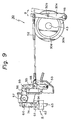
- FIG. 9 the structure of the third cam link mechanism 30 is shown in Fig. 9.
- a cam disc 30a is attached to the common cam shaft 43.
- a cam groove 30d is formed on the cam disc 30a.
- a cam follower (projection) 30b is formed on a swinging lever 30e attached to the common shaft 46, and this projection 30b is engaged with the groove 30d and is oscillated as indicated by an arrow B by rotation of the cam disc 30a. This oscillating movement is transmitted to a lever assembly of the cutting means 6 through a rod 52.
- the lever assembly comprises a first lever 54 pivoted on a stationary shaft 53, a second lever 55 connected to the first lever 54 through a shaft 58, a third lever 56 pivoted on a shaft 57 and connected to the second lever 55 through a shaft 59, and a shank 74 connected to the end of the third lever 56 through a shaft 60.
- the rod 52 and the first and second levers 54 and 55 form a toggle mechanism and the third lever 56 forms a bell crank mechanism.
- the lower end 61 of the shank 74 is rotatably connected to a supporting block 62 of a cutter 63.
- the rod 52 is connected to the shaft 58.
- FIG 10 is a perspective view of the inserter head 7.
- a head holder 37 is secured to a shaft 38.
- a slider 39 slidable as indicated by an arrow C relative to the head holder 37 is arranged within the head holder 37.
- a clamper 140 is arranged on the end portion (front end) of the slider 39.
- the clamper 140 comprises a lower plate 64 having parallel V-grooves for receiving connector pins and a pin-pressing upper plate 65 having projections (not shown) corresponding to the V-grooves and pressing the connector pins.
- the upper plate is arranged on the front end of a clamping plate 73, and the clamping plate 73 is connected to a cylinder 66 secured to the slider 39 through a bracket 141.
- the clamping plate 73 is attached to the top face of the slider 39 through swinging levers 67 and 68 pivoted on the slider 39.
- the swinging levers 67 and 68 are rotated in the direction of an arrow D to project the pin-pressing upper plate 65 forward and clamp the connector pins (not shown) in the V-grooves of the lower plate 64 by spring means not shown in the drawings (or by the elasticity of the upper plate per se).
- the clamper 140 clamps the gold-plated connecting portions 8a of the connector pins 8 (see Fig. 5) of the belt 2.
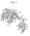
- FIG 11 illustrates the rotation mechanism of the inserter head 7 shown in Fig. 10.
- the rotation shaft 38 to which the inserter head 7 is secured is arranged in parallel to the feed direction (arrow F) of the continuous belt 2.
- a pinion 35 is secured to the rotation shaft 38, and a rack 36 to be engaged with this pinion 35 is attached to the top end of one arm of a lever 71 comprising two arms.
- the lever 71 is pivoted on a shaft 72 secured to a body frame (not shown) of the inserter apparatus.
- a rod 69 of the second cam link mechanism 29 is connected to the top end of the other arm of the lever 71.
- the swinging lever 29e is oscillated as indicated by an arrow B by the rotation of the cam disc 29a and the lever 71 is rotated around the shaft 72 to move the rack 36 in the vertical direction, whereby the pinion 35 is rotated and the inserter 7 is rotated.
- a spring 142 is arranged at the intermediate portion of the rod 69 to remove the back-lash of the rack-pinion gear.
- Figure 12 is a perspective view illustrating the appearance of the cutting means 6.
- the mechanism for driving the cutting means 6 is substantially the same as the mechanism shown in Fig. 9, though the two mechanisms differ in shape to some extend.
- Reference numeral 76 represents a cutting die for supporting the belt 2.
- the inserter head 7 is rotated by 90° by the above-mentioned rotation mechanism to direct downward the connector pins 8 held by the clamper 140.
- Means for checking the clamping state of the connector pins 8 is shown in Figure 13.
- a guide rail 75 guides the frame 21 to which the pins 8 are connected in comb-like form.
- a comb member 77 composed of a conductive material such as stainless steel is arranged on the inner side of a cutting recess 76a of the die 76 through an insulating plate 143. The pitch of comb teeth of the comb member 77 is the same as the pitch of the connector pins 8 of the belt 2.
- a pin check plate 78 formed of a conductive material such as stainless steel is arranged below the comb member 77 along the locus of the top end of the connector pin 8 moved by the rotation of the inserter head 7. As shown in Fig. 14, the pin check plate 78 preferably covers an area from below the comb member 77 to a point just before the position at which the inserter head 7 is rotated by 90°. If the clamping state of the connector pin is normal, as indicated by reference numeral 8-1 in Fig. 15, the connector pin 8-1 does not come into contact with any part of the pin check plate 78. The connector pin 8-2 has come out of alignment because of insufficient clamping during the rotation after the cutting operation.
- This connector pin 8-2 comes into contact with the inner wall of the comb member 77 or the pin check plate 78.
- the connector pin 8-3 has been clamped at an oblique angle by the clamper 140, and reference numeral 8-4 represents a bent or broken connector pin.
- Each of the connector pins 8-3 and 8-4 comes into contact with the comb member 77.
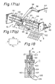
- FIG 16 is a diagram illustrating in detail the pin-inserting driving mechanism of the inserter head 7.
- a rod 80 of the fifth cam link mechanism 32 is connected to a toggle mechanism comprising levers 81 and 82.
- the top end of the lever 81 is vertically slidable in a stroke adjusting block 144 within a housing 84 secured to a body frame (not shown) of the inserter apparatus.
- the vertical movement of the end of the lever 81 is regulated by a screw 85.
- the position of the lower end of the screw 85 onto which the lever 81 impinges can be adjusted by rotating and driving the screw 85 by a worm gear motor 87 through a belt 86.
- the pressing block 40 has a pressing member 88 on the lower end thereof.
- the pressing surface of the lower end of the pressing member 88 has a concave arcuate shape corresponding to the convex arcuate surface of the end 89 of the slider 39 of the inserter head 7.
- the pressing member 88 is preferably secured to the pressing block 40 through an elastic member (not shown) formed of a urethane rubber or the like.
- FIG 17-(a) is a diagram illustrating in detail a feeding means 12 for the continuous belt 2.
- a slider block 41 is slidably mounted on two guide rods 151 and 152.
- a feed lever 95 secured to a rotation shaft 150 is attached to the front face of the slider block 41 so that the feed lever 95 can rotate relative to the slider block 41.
- a pin 96 to be engaged with the feed hole 22 of the belt frame 21 is arranged on the top end of the feed lever 95.
- a roller 94 is disposed on the end of the rotation shaft 150 through an arm 153.
- the arm 153 is always urged downward by a spring (not shown).
- the roller 94 rolls on a guide rail 93, and the guide rail 93 is secured to a shaft 92.
- a rod 90 connected to the cam disc of the sixth cam link mechanism 33 is connected to the end of the shaft 92 through a lever 91.
- a sliding piece 101 on the end of the lever 98 forming the seventh cam link mechanism 34 is anchored in a guide groove 100 on the top face of the slider block 41.
- a rod 97 connected to a cam disc not shown in the drawing is connected to the other end of the lever 98, which is mounted on pivot 99.
- cam groove shapes of the cam plates 33a and 34a of the sixth and seventh cam links 33 and 34 are appropriately adjusted, and the pin 96 of the feed lever 95 is moved rectangularly in the directions F1 ⁇ J1 ⁇ F2 ⁇ J2 as shown in Fig. 17-(b), whereby the belt frame 21 is intermittently fed synchronously with the respective processing operations (such as the cutting, clamping, and inserting operations).
- FIG. 18 An example of the detecting means for checking whether or not the connector pins 8 are properly inserted is illustrated in Fig. 18.
- a detecting pin 102 is arranged in the support means 11 for supporting the printed circuit board 9 from below at the time of the press insertion of the connector pins 8.
- the detecting pin 102 is urged upward by a spring 103.
- An electric contact 104 is formed below the detecting pin 102.
- the end of the pin depresses the detecting pin 102 and brings it down against the spring 103 and into contact with the electric contact 104, whereby a terminal 106 connected to the contact 104 is electrically connected to a terminal 105 connected to a metal case 107 of the support means 11.
- the contact 104 and the terminal 106 are supported by an insulator 150 which is installed in the metal case 107.
- FIG. 19 An example of the X-Y table having the printed circuit board loaded thereon is shown in Fig. 19.
- An X-table 109 and a Y-table 110 are placed on a base stand 108 so that they can be moved only in the X-direction and Y-direction, respectively.
- Each of the tables 109 and 110 is a rectangular frame, and the printed circuit board support means 11 (not shown) is arranged within the tables 109 and 110.
- FIG. 20 Another example of the X-Y table is shown in Fig. 20.
- an auxiliary Y-table 111 is arranged on the Y-table 110 so that the range of the movement in the Y-direction is expanded.
- Reference numeral 112 represents a cylinder for driving the auxiliary Y-table 111.
- an auxiliary X-table may be disposed so that the range of the movement in the X-direction is expanded.
- FIG. 21 shows a continuous belt 2 having a pitch PO 2.50 mm
- Fig. 22 shows a belt in which the pitch is expanded to P1 of 2.54 mm by forming a recess 113 between every two adjacent connector pins 8 by pressing.
- Pressing is accomplished, for example, by forming the recess 113 between every two adjacent holes 22 of the belt frame 21 by a pair of upper and lower pressing molds 116a and 116b having a pressing inclined face 155 as shown in Fig. 23.
- the thickness of the pressing mold is P1
- a stopper 117 to be projected toward the frame by a spring 118 is arranged on the side face of the pressing mold.
- the recesses 113 can be formed at the pitch P1.
- the feed pitch of the frame 21 is P0. In this manner, the continuous belt having the pitch PO can be changed to a belt having the pitch P1.
- FIG 24 is a block diagram of the control zone of the connector pin inserter according to the present invention.
- the X-Y table, the cam plates, and other parts of the inserter are sequentially controlled by a processor 123.
- the processor 123 is connected to a printer 120, a floppy 121, and a CRT display 122 through an interface circuit INT to read sequence program data, and to display and print the results of the processing.
- the processor 123 may be connected to a host computer 124 so that various production information and program data are input to the processor 123.
- the printed circuit board is loaded on the X-Y table 10 by a load and unload mechanism 133 consisting of a robot or the like.
- the kind of printed circuit board is detected by a board detector 134.
- a hole is formed on the printed circuit board in advance, marking is effected by attachment of a metal plate or the like, and this mark is read by an optical detector, whereby the kind of printed circuit board is discriminated.
- the detection data of the kind of printed circuit board is input to the processor 123. Based on this data, from a data file in the floppy 121, data for the pin insertion depth according to the thickness of the printed circuit board, the number of pins, and the arrangement order is selected.
- the processor 123 drives an X-motor 124 and a Y-motor 128 through an X-control circuit 125 and a Y-control circuit 127 to automatically move and control the X-Y table 10.
- An X-detector 126 and a Y-detector 129, each comprising an encoder or the like, are connected to the X-motor and Y-motor, respectively, to detect the positions of the X-table and Y-table. The detection data is fed back to the X-control circuit 125 and Y-control circuit 127 to perform feedback control of the X-motor 124 and Y-motor 128.
- a press insertion control circuit 132 for driving a cam disc driving motor, a press insertion stroke adjusting motor, and a cylinder driving circuit for performing a series of operations of press-inserting the pins by a pin press insertion mechanism 130 comprising cam means, is controlled according to the kind of printed circuit board detected by the processor 123.
- An error signal or termination signal from a pin detector 131 comprising the means (see Figs. 13, 14, and 15) for checking the clamping state of the pins, which is arranged in the pin cutting zone, and/or the press insertion detecting means (Fig. 18) arranged within the printed circuit board support means 11, is input to the processor 123 to actuate an alarm not shown in the drawing and stop the pin press insertion operation.
- connector pin inserter since connector pins are integrally connected in the form of a continuous comb-shaped belt (carrier), a series of pin attaching operations such as pin feeding, clamping, and press insertion can be completely automated, and productivity can be increased.
- the plating operation can be facilitated.
- a clamper By clamping the gold-plated top portions by a clamper, cutting the root portion of the respective teeth, and inserting pins from these root portions into a printed circuit board, the peeling of plated gold of the pin top can be prevented at the press insertion step.
Landscapes
- Engineering & Computer Science (AREA)
- Manufacturing & Machinery (AREA)
- Microelectronics & Electronic Packaging (AREA)
- Manufacturing Of Electrical Connectors (AREA)
- Supply And Installment Of Electrical Components (AREA)
Applications Claiming Priority (2)
| Application Number | Priority Date | Filing Date | Title |
|---|---|---|---|
| JP274530/84 | 1984-12-28 | ||
| JP59274530A JPS61156800A (ja) | 1984-12-28 | 1984-12-28 | コネクタピンインサ−タ |
Publications (2)
| Publication Number | Publication Date |
|---|---|
| EP0188003A1 EP0188003A1 (en) | 1986-07-23 |
| EP0188003B1 true EP0188003B1 (en) | 1990-03-14 |
Family
ID=17542989
Family Applications (1)
| Application Number | Title | Priority Date | Filing Date |
|---|---|---|---|
| EP85116621A Expired - Lifetime EP0188003B1 (en) | 1984-12-28 | 1985-12-27 | Connector pin inserter |
Country Status (6)
| Country | Link |
|---|---|
| US (1) | US4672735A (https=) |
| EP (1) | EP0188003B1 (https=) |
| JP (1) | JPS61156800A (https=) |
| KR (1) | KR900003234B1 (https=) |
| CA (1) | CA1237822A (https=) |
| DE (1) | DE3576618D1 (https=) |
Families Citing this family (42)
| Publication number | Priority date | Publication date | Assignee | Title |
|---|---|---|---|---|
| US4894911A (en) * | 1989-02-09 | 1990-01-23 | Gte Products Corporation | Method and apparatus for loading electrical contacts into a connector body |
| US5095609A (en) * | 1990-03-29 | 1992-03-17 | Amp Incorporated | Work piece assembly machine |
| JPH07212005A (ja) * | 1994-01-21 | 1995-08-11 | Pioneer Electron Corp | Pcb作成装置 |
| EP0755102A3 (en) * | 1995-07-21 | 1997-08-13 | Gregory W Holcomb | Continuous supply of strip of straight connectors |
| US5727305A (en) * | 1996-01-25 | 1998-03-17 | Alvite; Joseph | Programmable pin feeder |
| JPH10208844A (ja) * | 1997-01-28 | 1998-08-07 | Harness Sogo Gijutsu Kenkyusho:Kk | ワイヤーハーネス用コネクタ端子の実装装置 |
| JP3067100B2 (ja) * | 1997-12-05 | 2000-07-17 | 株式会社 天翔 | 部品自動圧入装置 |
| US6141869A (en) * | 1998-10-26 | 2000-11-07 | Silicon Bandwidth, Inc. | Apparatus for and method of manufacturing a semiconductor die carrier |
| US6412768B1 (en) * | 1999-09-01 | 2002-07-02 | Micron Technology, Inc. | Self-adjusting printed circuit board support and method of use |
| JP4637403B2 (ja) * | 2001-06-06 | 2011-02-23 | 富士機械製造株式会社 | 電気部品装着システム |
| KR20050083173A (ko) * | 2002-03-13 | 2005-08-26 | 주식회사 탑이엔지 | 컨넥터의 접속핀 조립장치 |
| KR20050083174A (ko) * | 2002-03-13 | 2005-08-26 | 주식회사 탑이엔지 | 컨넥터의 보강판 조립장치 |
| KR100519499B1 (ko) * | 2002-11-02 | 2005-10-07 | 박준석 | 인쇄회로기판 검사장비용 테스트핀 구동장치 |
| DE102007054454B4 (de) * | 2007-11-13 | 2010-08-26 | Tyco Electronics Amp Gmbh | Vorrichtung und Verfahren zum Bestücken von Leiterplatten mit Kontaktstiften |
| DE102008051483A1 (de) * | 2008-10-13 | 2010-04-22 | Tyco Electronics Amp Gmbh | Greifeinrichtung und Verfahren zum Zuführen von Kontaktelementen |
| DE102009046589B3 (de) * | 2009-11-10 | 2011-07-07 | Tyco Electronics AMP GmbH, 64625 | Verfahren und Vorrichtung zum Bestimmen einer Abstandsposition eines Kontaktendes zu einer Leiterplatte |
| CN104907385A (zh) * | 2015-07-02 | 2015-09-16 | 吴中区横泾博尔机械厂 | 可调式插针机的插针下冲切机构 |
| CN105633765A (zh) * | 2016-01-26 | 2016-06-01 | 东莞市创玺自动化科技有限公司 | Fpc凸轮插针机 |
| CN107271826B (zh) * | 2016-04-06 | 2019-11-15 | 无锡华润华晶微电子有限公司 | 一种针对编带上器件的测试系统 |
| CN106391825A (zh) * | 2016-12-14 | 2017-02-15 | 台山市爱达电器厂有限公司 | 高精度切断装置及其高精度冲孔切断设备 |
| CN107155290B (zh) * | 2017-04-21 | 2019-10-29 | 江苏大学 | 一种电路板自动回转式切脚机及其作业方法 |
| CN111180978B (zh) * | 2017-08-22 | 2021-06-29 | 东莞市蓉工自动化科技有限公司 | 一种能够检测的二极插头连续插针设备 |
| CN107645114A (zh) * | 2017-11-14 | 2018-01-30 | 苏州泛能电力科技有限公司 | 一种电连接器十针料排上料压合装置 |
| CN108513484B (zh) * | 2018-04-19 | 2020-08-14 | 北京圣龙缘科技有限公司 | 一种电子元器件的组装装置 |
| CN109107921B (zh) * | 2018-08-16 | 2024-01-30 | 广东铭基高科电子股份有限公司 | 电测及视觉检测系统 |
| CN109905977B (zh) * | 2019-03-25 | 2024-02-20 | 宗智辉 | 散料端子插片机构 |
| CN110193715B (zh) * | 2019-06-28 | 2024-07-23 | 深圳市运泰利自动化设备有限公司 | 一种电子接插件自动冲切组装设备 |
| CN110299660B (zh) * | 2019-07-11 | 2024-03-26 | 江苏倚信自动化设备有限公司 | 一种电子凸轮插针机构 |
| CN111029884B (zh) * | 2019-12-31 | 2025-01-24 | 昆山博思达自动化设备科技有限公司 | 一种圆针高速插针机构 |
| CN111490434B (zh) * | 2020-05-12 | 2025-02-14 | 东莞市锐华自动化设备有限公司 | 胶壳转换装置及其方法 |
| CN112775359B (zh) * | 2021-01-29 | 2022-09-27 | 重庆溢哲渝科技有限公司 | 一种电子元器件引脚剪切成形装置 |
| CN113410724B (zh) * | 2021-05-13 | 2022-05-31 | 佛山市炫瑞电子科技有限公司 | 一种btb连接器的针脚插入装置 |
| CN116330381B (zh) * | 2021-09-30 | 2025-09-12 | 福建迈可博电子科技集团股份有限公司 | 一种多动作联动的射频连接器绝缘子对切装置 |
| CN114597733B (zh) * | 2022-03-24 | 2024-04-19 | 苏州市锐翊电子科技有限公司 | 连接器插接设备 |
| DE102022107782B4 (de) * | 2022-04-01 | 2023-10-12 | ASMPT GmbH & Co. KG | Vorrichtung und Verfahren zum Zuführen von Komponenten für einen Bestückautomaten, Bestücksystem |
| CN115741048B (zh) * | 2022-11-22 | 2025-07-04 | 广东冠能电力科技发展有限公司 | 一种自动上销机构 |
| CN116404498A (zh) * | 2023-03-15 | 2023-07-07 | 富加宜连接器(东莞)有限公司 | 一种通用的排针高速自动插针设备 |
| CN119297697B (zh) * | 2024-07-18 | 2025-11-28 | 东莞市邦泰自动化科技有限公司 | 一种CPU Socket高速插针设备 |
| CN118763483B (zh) * | 2024-07-26 | 2025-10-17 | 皓星智能装备(东莞)有限公司 | 一种针脚加工设备 |
| CN119009617B (zh) * | 2024-09-09 | 2025-04-04 | 惠州奥华智能科技有限公司 | 一种连接器的插针折弯设备 |
| DE102024129533A1 (de) * | 2024-10-11 | 2026-04-16 | HAHN Automation Group Diepenau GmbH | Stiftkontakteinsetzmaschine und verfahren zum setzen von stiftkontakten in ein kunststoffbauteil |
| DE102024129534A1 (de) * | 2024-10-11 | 2026-04-16 | HAHN Automation Group Diepenau GmbH | Stiftkontakteinsetzmaschine und verfahren zum setzen von stiftkontakten in ein kunststoffbauteil |
Family Cites Families (16)
| Publication number | Priority date | Publication date | Assignee | Title |
|---|---|---|---|---|
| US3276653A (en) * | 1964-08-24 | 1966-10-04 | Amp Inc | Contact inserting apparatus |
| US3566464A (en) * | 1968-12-05 | 1971-03-02 | Berg Electronics Inc | Apparatus and method for mounting wire wrap pins on circuit boards |
| US3722062A (en) * | 1971-11-04 | 1973-03-27 | Warwick Electronics Inc | Component insertion system |
| US3765075A (en) * | 1972-01-03 | 1973-10-16 | Honeywell Inf Systems | Method and apparatus for inserting pins into a circuit board |
| FR2225914B1 (https=) * | 1973-04-11 | 1975-08-22 | Comatel | |
| CA1031138A (en) * | 1974-03-28 | 1978-05-16 | Amp Incorporated | Terminal insertion apparatus |
| US4058881A (en) * | 1976-01-21 | 1977-11-22 | E. I. Du Pont De Nemours And Company | Application machine for mounting circuit board pins with an improved control system |
| JPS5388280A (en) * | 1977-01-12 | 1978-08-03 | Matsushita Electric Ind Co Ltd | Pin inserting device and method therefor |
| US4290178A (en) * | 1978-05-10 | 1981-09-22 | International Telephone And Telegraph Corporation | Assembly apparatus for electrical connectors |
| US4365398A (en) * | 1978-11-30 | 1982-12-28 | Western Electric Company, Inc. | Method of and apparatus for assembling intermediate-web held terminal pins |
| US4265013A (en) * | 1979-05-10 | 1981-05-05 | Methode Electronics, Inc. | Apparatus for driving pins into a printed circuit board and the like |
| US4372044A (en) * | 1980-10-31 | 1983-02-08 | Western Electric Company, Inc. | Method of and apparatus for straightening terminal pins |
| DE3119686A1 (de) * | 1981-05-18 | 1982-12-02 | Siemens AG, 1000 Berlin und 8000 München | Be- und entstueckautomat fuer bauelemente |
| US4506438A (en) * | 1981-11-02 | 1985-03-26 | Elfab Corporation | Apparatus for manufacturing integrated circuit connectors |
| US4464833A (en) * | 1982-09-01 | 1984-08-14 | Usm Corporation | Variable rate control logic for component insertion machine |
| US4551901A (en) * | 1984-02-24 | 1985-11-12 | Amp Incorporated | Component insertion apparatus |
-
1984
- 1984-12-28 JP JP59274530A patent/JPS61156800A/ja active Granted
-
1985
- 1985-12-23 CA CA000498504A patent/CA1237822A/en not_active Expired
- 1985-12-24 KR KR1019850009761A patent/KR900003234B1/ko not_active Expired
- 1985-12-27 EP EP85116621A patent/EP0188003B1/en not_active Expired - Lifetime
- 1985-12-27 DE DE8585116621T patent/DE3576618D1/de not_active Expired - Lifetime
- 1985-12-27 US US06/813,945 patent/US4672735A/en not_active Expired - Lifetime
Also Published As
| Publication number | Publication date |
|---|---|
| DE3576618D1 (de) | 1990-04-19 |
| CA1237822A (en) | 1988-06-07 |
| US4672735A (en) | 1987-06-16 |
| JPS61156800A (ja) | 1986-07-16 |
| EP0188003A1 (en) | 1986-07-23 |
| KR860005461A (ko) | 1986-07-23 |
| JPH0315838B2 (https=) | 1991-03-04 |
| KR900003234B1 (ko) | 1990-05-11 |
Similar Documents
| Publication | Publication Date | Title |
|---|---|---|
| EP0188003B1 (en) | Connector pin inserter | |
| US3769679A (en) | Apparatus for manufacturing connector terminals | |
| US3594889A (en) | Terminal-inserting machines having improved inside former | |
| EP0321214B1 (en) | Cable harness manufacturing and electrical testing system | |
| EP0001891B1 (en) | Apparatus for inserting wires into electrical terminals | |
| EP0386893A2 (en) | Modular application tooling for electrical connectors | |
| EP0145216B1 (en) | Harness making machine and method and improved wire jig therefor | |
| JP2520066B2 (ja) | 電力線ハ―ネスの製造装置及び製造方法 | |
| US4766668A (en) | Pitch transition wire guide apparatus | |
| JPH0237068B2 (https=) | ||
| US3765073A (en) | Apparatus for assembling a component of parts comprising terminations, conductor leads and enclosures | |
| CN213602161U (zh) | 电连接器组装装置 | |
| US4372044A (en) | Method of and apparatus for straightening terminal pins | |
| EP0476358B1 (en) | Machine for making the electrical connection of an electrical connection device | |
| US4763412A (en) | Method and apparatus for inserting pins in a substrate | |
| EP0090050A1 (en) | Device for inserting electric part | |
| US5778527A (en) | Apparatus and method for forming "L"-shaped terminals from structures stamped in a flat strip and for inserting such terminals into an electronic package | |
| US3967370A (en) | Method of manufacturing a multicontact switch | |
| JP3681455B2 (ja) | ワイヤ圧接接続装置 | |
| US4651413A (en) | Wire jig intended for use in a harness-making machine or the like | |
| JPH06268021A (ja) | フィルムキャリア打抜き金型 | |
| US4519132A (en) | High speed contact insertion facility | |
| US3896285A (en) | Process and device for welding of multiwire cables | |
| JPS59226482A (ja) | 自動圧接機 | |
| US5153989A (en) | Process of producing electrical terminal with electrical contacts and system thereof |
Legal Events
| Date | Code | Title | Description |
|---|---|---|---|
| PUAI | Public reference made under article 153(3) epc to a published international application that has entered the european phase |
Free format text: ORIGINAL CODE: 0009012 |
|
| AK | Designated contracting states |
Kind code of ref document: A1 Designated state(s): DE FR GB SE |
|
| 17P | Request for examination filed |
Effective date: 19860818 |
|
| 17Q | First examination report despatched |
Effective date: 19880509 |
|
| GRAA | (expected) grant |
Free format text: ORIGINAL CODE: 0009210 |
|
| AK | Designated contracting states |
Kind code of ref document: B1 Designated state(s): DE FR GB SE |
|
| REF | Corresponds to: |
Ref document number: 3576618 Country of ref document: DE Date of ref document: 19900419 |
|
| ET | Fr: translation filed | ||
| PLBE | No opposition filed within time limit |
Free format text: ORIGINAL CODE: 0009261 |
|
| STAA | Information on the status of an ep patent application or granted ep patent |
Free format text: STATUS: NO OPPOSITION FILED WITHIN TIME LIMIT |
|
| 26N | No opposition filed | ||
| EAL | Se: european patent in force in sweden |
Ref document number: 85116621.5 |
|
| PGFP | Annual fee paid to national office [announced via postgrant information from national office to epo] |
Ref country code: SE Payment date: 19981207 Year of fee payment: 14 |
|
| PGFP | Annual fee paid to national office [announced via postgrant information from national office to epo] |
Ref country code: FR Payment date: 19981209 Year of fee payment: 14 |
|
| PGFP | Annual fee paid to national office [announced via postgrant information from national office to epo] |
Ref country code: GB Payment date: 19981231 Year of fee payment: 14 |
|
| PGFP | Annual fee paid to national office [announced via postgrant information from national office to epo] |
Ref country code: DE Payment date: 19990107 Year of fee payment: 14 |
|
| PG25 | Lapsed in a contracting state [announced via postgrant information from national office to epo] |
Ref country code: GB Free format text: LAPSE BECAUSE OF NON-PAYMENT OF DUE FEES Effective date: 19991227 |
|
| PG25 | Lapsed in a contracting state [announced via postgrant information from national office to epo] |
Ref country code: SE Free format text: LAPSE BECAUSE OF NON-PAYMENT OF DUE FEES Effective date: 19991228 |
|
| EUG | Se: european patent has lapsed |
Ref document number: 85116621.5 |
|
| GBPC | Gb: european patent ceased through non-payment of renewal fee |
Effective date: 19991227 |
|
| PG25 | Lapsed in a contracting state [announced via postgrant information from national office to epo] |
Ref country code: FR Free format text: LAPSE BECAUSE OF NON-PAYMENT OF DUE FEES Effective date: 20000831 |
|
| PG25 | Lapsed in a contracting state [announced via postgrant information from national office to epo] |
Ref country code: DE Free format text: LAPSE BECAUSE OF NON-PAYMENT OF DUE FEES Effective date: 20001003 |
|
| REG | Reference to a national code |
Ref country code: FR Ref legal event code: ST |