EP0187145B1 - Nickel-hydrogen bipolar battery - Google Patents
Nickel-hydrogen bipolar battery Download PDFInfo
- Publication number
- EP0187145B1 EP0187145B1 EP19850901279 EP85901279A EP0187145B1 EP 0187145 B1 EP0187145 B1 EP 0187145B1 EP 19850901279 EP19850901279 EP 19850901279 EP 85901279 A EP85901279 A EP 85901279A EP 0187145 B1 EP0187145 B1 EP 0187145B1
- Authority
- EP
- European Patent Office
- Prior art keywords
- hydrogen
- unit cell
- electrode
- battery
- nickel
- Prior art date
- Legal status (The legal status is an assumption and is not a legal conclusion. Google has not performed a legal analysis and makes no representation as to the accuracy of the status listed.)
- Expired - Lifetime
Links
- 239000001257 hydrogen Substances 0.000 title claims abstract description 88
- 229910052739 hydrogen Inorganic materials 0.000 title claims abstract description 88
- PXHVJJICTQNCMI-UHFFFAOYSA-N Nickel Chemical compound [Ni] PXHVJJICTQNCMI-UHFFFAOYSA-N 0.000 claims abstract description 109
- UFHFLCQGNIYNRP-UHFFFAOYSA-N Hydrogen Chemical compound [H][H] UFHFLCQGNIYNRP-UHFFFAOYSA-N 0.000 claims abstract description 84
- 229910052759 nickel Inorganic materials 0.000 claims abstract description 54
- BASFCYQUMIYNBI-UHFFFAOYSA-N platinum Chemical compound [Pt] BASFCYQUMIYNBI-UHFFFAOYSA-N 0.000 claims abstract description 26
- MYMOFIZGZYHOMD-UHFFFAOYSA-N Dioxygen Chemical compound O=O MYMOFIZGZYHOMD-UHFFFAOYSA-N 0.000 claims abstract description 18
- 229910001882 dioxygen Inorganic materials 0.000 claims abstract description 18
- 230000006798 recombination Effects 0.000 claims abstract description 15
- 238000005215 recombination Methods 0.000 claims abstract description 15
- 229910052697 platinum Inorganic materials 0.000 claims abstract description 13
- 230000000712 assembly Effects 0.000 claims abstract description 11
- 238000000429 assembly Methods 0.000 claims abstract description 11
- 239000003792 electrolyte Substances 0.000 claims description 40
- 238000001816 cooling Methods 0.000 claims description 35
- XLYOFNOQVPJJNP-UHFFFAOYSA-N water Substances O XLYOFNOQVPJJNP-UHFFFAOYSA-N 0.000 claims description 25
- 239000001301 oxygen Substances 0.000 claims description 19
- 229910052760 oxygen Inorganic materials 0.000 claims description 19
- 239000004020 conductor Substances 0.000 claims description 18
- 239000007789 gas Substances 0.000 claims description 18
- QVGXLLKOCUKJST-UHFFFAOYSA-N atomic oxygen Chemical compound [O] QVGXLLKOCUKJST-UHFFFAOYSA-N 0.000 claims description 17
- 239000002826 coolant Substances 0.000 claims description 16
- KWYUFKZDYYNOTN-UHFFFAOYSA-M Potassium hydroxide Chemical compound [OH-].[K+] KWYUFKZDYYNOTN-UHFFFAOYSA-M 0.000 claims description 15
- 239000012530 fluid Substances 0.000 claims description 14
- 230000002209 hydrophobic effect Effects 0.000 claims description 13
- 238000003487 electrochemical reaction Methods 0.000 claims description 6
- 229920000642 polymer Polymers 0.000 claims description 4
- 239000011149 active material Substances 0.000 claims description 3
- -1 polytetrafluoroethylene Polymers 0.000 claims description 3
- 229920001343 polytetrafluoroethylene Polymers 0.000 claims description 3
- 239000004810 polytetrafluoroethylene Substances 0.000 claims description 3
- OKTJSMMVPCPJKN-UHFFFAOYSA-N Carbon Chemical compound [C] OKTJSMMVPCPJKN-UHFFFAOYSA-N 0.000 claims description 2
- 239000004215 Carbon black (E152) Substances 0.000 claims description 2
- 239000007864 aqueous solution Substances 0.000 claims description 2
- 230000006835 compression Effects 0.000 claims description 2
- 238000007906 compression Methods 0.000 claims description 2
- 239000003989 dielectric material Substances 0.000 claims description 2
- 229910002804 graphite Inorganic materials 0.000 claims description 2
- 239000010439 graphite Substances 0.000 claims description 2
- 229930195733 hydrocarbon Natural products 0.000 claims description 2
- 150000002430 hydrocarbons Chemical class 0.000 claims description 2
- XLYOFNOQVPJJNP-UHFFFAOYSA-M hydroxide Chemical compound [OH-] XLYOFNOQVPJJNP-UHFFFAOYSA-M 0.000 claims description 2
- 229910000480 nickel oxide Inorganic materials 0.000 claims description 2
- GNRSAWUEBMWBQH-UHFFFAOYSA-N oxonickel Chemical compound [Ni]=O GNRSAWUEBMWBQH-UHFFFAOYSA-N 0.000 claims description 2
- 239000011248 coating agent Substances 0.000 claims 6
- 238000000576 coating method Methods 0.000 claims 6
- 230000005611 electricity Effects 0.000 claims 1
- 229910052751 metal Inorganic materials 0.000 claims 1
- 239000002184 metal Substances 0.000 claims 1
- 239000003643 water by type Substances 0.000 claims 1
- 239000003054 catalyst Substances 0.000 abstract description 8
- 210000004027 cell Anatomy 0.000 description 146
- 239000000463 material Substances 0.000 description 8
- MCMNRKCIXSYSNV-UHFFFAOYSA-N Zirconium dioxide Chemical compound O=[Zr]=O MCMNRKCIXSYSNV-UHFFFAOYSA-N 0.000 description 6
- 230000008901 benefit Effects 0.000 description 6
- 239000011148 porous material Substances 0.000 description 5
- 238000007599 discharging Methods 0.000 description 4
- 238000005868 electrolysis reaction Methods 0.000 description 4
- 239000004744 fabric Substances 0.000 description 4
- 239000011159 matrix material Substances 0.000 description 4
- 230000007246 mechanism Effects 0.000 description 4
- 230000003071 parasitic effect Effects 0.000 description 4
- 230000005012 migration Effects 0.000 description 3
- 238000013508 migration Methods 0.000 description 3
- 239000004809 Teflon Substances 0.000 description 2
- 229920006362 Teflon® Polymers 0.000 description 2
- 230000009471 action Effects 0.000 description 2
- 238000006243 chemical reaction Methods 0.000 description 2
- 238000009792 diffusion process Methods 0.000 description 2
- 238000001035 drying Methods 0.000 description 2
- 230000009977 dual effect Effects 0.000 description 2
- 230000008030 elimination Effects 0.000 description 2
- 238000003379 elimination reaction Methods 0.000 description 2
- 239000012528 membrane Substances 0.000 description 2
- 150000002926 oxygen Chemical class 0.000 description 2
- 239000000243 solution Substances 0.000 description 2
- 239000012670 alkaline solution Substances 0.000 description 1
- 210000003850 cellular structure Anatomy 0.000 description 1
- 230000008859 change Effects 0.000 description 1
- 230000000295 complement effect Effects 0.000 description 1
- 238000010276 construction Methods 0.000 description 1
- 238000010292 electrical insulation Methods 0.000 description 1
- 238000000605 extraction Methods 0.000 description 1
- 229920002313 fluoropolymer Polymers 0.000 description 1
- 150000002431 hydrogen Chemical class 0.000 description 1
- 150000002500 ions Chemical class 0.000 description 1
- 239000011244 liquid electrolyte Substances 0.000 description 1
- 238000012986 modification Methods 0.000 description 1
- 230000004048 modification Effects 0.000 description 1
- 229910021508 nickel(II) hydroxide Inorganic materials 0.000 description 1
- BFDHFSHZJLFAMC-UHFFFAOYSA-L nickel(ii) hydroxide Chemical compound [OH-].[OH-].[Ni+2] BFDHFSHZJLFAMC-UHFFFAOYSA-L 0.000 description 1
- 239000012811 non-conductive material Substances 0.000 description 1
- RVTZCBVAJQQJTK-UHFFFAOYSA-N oxygen(2-);zirconium(4+) Chemical compound [O-2].[O-2].[Zr+4] RVTZCBVAJQQJTK-UHFFFAOYSA-N 0.000 description 1
- 239000002861 polymer material Substances 0.000 description 1
- 230000036647 reaction Effects 0.000 description 1
- 230000009467 reduction Effects 0.000 description 1
- 239000000126 substance Substances 0.000 description 1
- 229910001928 zirconium oxide Inorganic materials 0.000 description 1
Images


Classifications
-
- F—MECHANICAL ENGINEERING; LIGHTING; HEATING; WEAPONS; BLASTING
- F28—HEAT EXCHANGE IN GENERAL
- F28F—DETAILS OF HEAT-EXCHANGE AND HEAT-TRANSFER APPARATUS, OF GENERAL APPLICATION
- F28F3/00—Plate-like or laminated elements; Assemblies of plate-like or laminated elements
- F28F3/12—Elements constructed in the shape of a hollow panel, e.g. with channels
-
- F—MECHANICAL ENGINEERING; LIGHTING; HEATING; WEAPONS; BLASTING
- F28—HEAT EXCHANGE IN GENERAL
- F28F—DETAILS OF HEAT-EXCHANGE AND HEAT-TRANSFER APPARATUS, OF GENERAL APPLICATION
- F28F3/00—Plate-like or laminated elements; Assemblies of plate-like or laminated elements
- F28F3/08—Elements constructed for building-up into stacks, e.g. capable of being taken apart for cleaning
- F28F3/083—Elements constructed for building-up into stacks, e.g. capable of being taken apart for cleaning capable of being taken apart
-
- H—ELECTRICITY
- H01—ELECTRIC ELEMENTS
- H01M—PROCESSES OR MEANS, e.g. BATTERIES, FOR THE DIRECT CONVERSION OF CHEMICAL ENERGY INTO ELECTRICAL ENERGY
- H01M10/00—Secondary cells; Manufacture thereof
- H01M10/04—Construction or manufacture in general
- H01M10/0413—Large-sized flat cells or batteries for motive or stationary systems with plate-like electrodes
- H01M10/0418—Large-sized flat cells or batteries for motive or stationary systems with plate-like electrodes with bipolar electrodes
-
- H—ELECTRICITY
- H01—ELECTRIC ELEMENTS
- H01M—PROCESSES OR MEANS, e.g. BATTERIES, FOR THE DIRECT CONVERSION OF CHEMICAL ENERGY INTO ELECTRICAL ENERGY
- H01M10/00—Secondary cells; Manufacture thereof
- H01M10/34—Gastight accumulators
- H01M10/345—Gastight metal hydride accumulators
-
- H—ELECTRICITY
- H01—ELECTRIC ELEMENTS
- H01M—PROCESSES OR MEANS, e.g. BATTERIES, FOR THE DIRECT CONVERSION OF CHEMICAL ENERGY INTO ELECTRICAL ENERGY
- H01M10/00—Secondary cells; Manufacture thereof
- H01M10/60—Heating or cooling; Temperature control
- H01M10/61—Types of temperature control
- H01M10/613—Cooling or keeping cold
-
- H—ELECTRICITY
- H01—ELECTRIC ELEMENTS
- H01M—PROCESSES OR MEANS, e.g. BATTERIES, FOR THE DIRECT CONVERSION OF CHEMICAL ENERGY INTO ELECTRICAL ENERGY
- H01M10/00—Secondary cells; Manufacture thereof
- H01M10/60—Heating or cooling; Temperature control
- H01M10/65—Means for temperature control structurally associated with the cells
- H01M10/654—Means for temperature control structurally associated with the cells located inside the innermost case of the cells, e.g. mandrels, electrodes or electrolytes
-
- H—ELECTRICITY
- H01—ELECTRIC ELEMENTS
- H01M—PROCESSES OR MEANS, e.g. BATTERIES, FOR THE DIRECT CONVERSION OF CHEMICAL ENERGY INTO ELECTRICAL ENERGY
- H01M10/00—Secondary cells; Manufacture thereof
- H01M10/60—Heating or cooling; Temperature control
- H01M10/65—Means for temperature control structurally associated with the cells
- H01M10/655—Solid structures for heat exchange or heat conduction
- H01M10/6556—Solid parts with flow channel passages or pipes for heat exchange
- H01M10/6557—Solid parts with flow channel passages or pipes for heat exchange arranged between the cells
-
- Y—GENERAL TAGGING OF NEW TECHNOLOGICAL DEVELOPMENTS; GENERAL TAGGING OF CROSS-SECTIONAL TECHNOLOGIES SPANNING OVER SEVERAL SECTIONS OF THE IPC; TECHNICAL SUBJECTS COVERED BY FORMER USPC CROSS-REFERENCE ART COLLECTIONS [XRACs] AND DIGESTS
- Y02—TECHNOLOGIES OR APPLICATIONS FOR MITIGATION OR ADAPTATION AGAINST CLIMATE CHANGE
- Y02E—REDUCTION OF GREENHOUSE GAS [GHG] EMISSIONS, RELATED TO ENERGY GENERATION, TRANSMISSION OR DISTRIBUTION
- Y02E60/00—Enabling technologies; Technologies with a potential or indirect contribution to GHG emissions mitigation
- Y02E60/10—Energy storage using batteries
-
- Y—GENERAL TAGGING OF NEW TECHNOLOGICAL DEVELOPMENTS; GENERAL TAGGING OF CROSS-SECTIONAL TECHNOLOGIES SPANNING OVER SEVERAL SECTIONS OF THE IPC; TECHNICAL SUBJECTS COVERED BY FORMER USPC CROSS-REFERENCE ART COLLECTIONS [XRACs] AND DIGESTS
- Y02—TECHNOLOGIES OR APPLICATIONS FOR MITIGATION OR ADAPTATION AGAINST CLIMATE CHANGE
- Y02P—CLIMATE CHANGE MITIGATION TECHNOLOGIES IN THE PRODUCTION OR PROCESSING OF GOODS
- Y02P70/00—Climate change mitigation technologies in the production process for final industrial or consumer products
- Y02P70/50—Manufacturing or production processes characterised by the final manufactured product
Definitions
- This invention relates generally to nickel-hydrogen batteries and more particularly to a nickel-hydrogen battery having a bipolar structure.
- a typical prior art nickel-hydrogen battery comprises a hydrogen gas filled pressure vessel in which a single or a pair of cells are located. Each cell has a positive nickel electrode spaced apart from a negative hydrogen electrode. A separator is located between the nickel and hydrogen electrodes. Each separator is sufficiently thick to prevent electrical shorting between the electrodes. In addition, each separator holds electrolyte therein to allow an electrochemical reaction to occur in the cell.
- the electrolyte is an aqueous alkaline solution, preferrably a solution of potassium hydroxide.
- oxygen gas is produced in the cell by the electrolysis of water in the electrolyte. This oxygen must be recombined with the pressure vessel hydrogen gas to form water within the cell to prevent the build up of oxygen gas pressure and a drying out of the separator. A build up of oxygen gas pressure may cause a breach in the pressure vessel structure. Separator dryout can lead to reduction in cell performance and a shortened cell lifetime.
- pairs of cells are arranged with the nickel electrodes in a back to back configuration.
- This is illustrated in U.S. Patent No. 4,115,630 issued to Van Ommering et al, and U.S. Patent No. 4,127,703, issued to Holleck.
- the Van Ommering et al patent describes a stack of cells wherein a cell pair, or module, is separated from an adjacent module by a module separator. The module separator prevents electrolyte contact between adjacent modules and the cells contained within the adjacent modules.
- the Holleck patent also describes a back to back arrangement of cell pairs.
- the Holleck patent includes an electrolyte reservoir and a microporous hydrophobic membrane between the back to back electrodes.
- the membrane permits gas and vapor to flow therethrough while being impermeable to the liquid electrolyte.
- the Holleck patent further describes a cell stack wherein a single positive configuration is used. In this configuration there is transport of oxygen gas evolved in one cell to an adjacent cell where it is recombined. This arrangement leads to oxygen gas transport in a single direction. Holleck provides for returning the oxygen at one end through a return conduit to the other end for oxygen-hydrogen recombination. This oxygen return scheme prevents an asymmetric buildup of water in the cell stack. Thus, this single positive configuration also results in the exchange of water between cells.
- U.S. Patent No. 3,975,210 issued to Warnock, also describes a plurality of paired cells within a single pressure vessel, each cell pair is contained with an individual compartment or module.
- the modules are con structed to permit hydrogen gas flow into the module but restricts electrolyte from leaving. Therefore, the loss of electrolyte and water from the module is minimized.
- the cell pair shares water in the module as does the previously described prior art patents.
- US-A-3,867,199 discloses a rechargeable Ni/H2 power cell essentially including a case, a plurality of positive electrodes in said case each positive electrode comprising Ni(OH)2 in the discharged stated at least one dual porosity negative electrode in said case comprising two conductive supports having a catalyst disposed in a hydrophobic non-conducting matrix mounted on each of said supports and means between said supports for providing passages for diffusion of gas to said catalyst, said catalyst being a material capable of dissociating molecular hydrogen to monatomic hydrogen, a plurality of porus matrices in said case, each porus matrix separating one of said positive electrodes and one of said conductive supports of said dual porosity negative electrode, an alkaline electrolyte in the pores of said matrix, a supply of hydrogen in said case surrounding said electrodes and matrix, said case being hermetically sealed to prevent inflow and outflow of gas during charging and discharging of said cell.
- the single battery cells disclosed in US-A3,867,199 comprise stacks of positive and negative electrodes and matrices with the like electrodes connected to each other. On a preferred embodiment there are suggested holes in the electrode to facilitate gas diffusion.
- the nickel electrodes are electrically connected in parallel.
- the hydrogen electrodes are also electrically connected in parallel.
- Each electrode has a tab which is then connected to a busbar for the respective nickel or hydrogen electrodes.
- a nickel-hydrogen battery having a bipolar cell configuration alleviates the need for electrode connecting tabs and busbars. By eliminating electrode tabs and busbars, significant weight savings can be obtained in a large system.
- a bipolar cell configuration a plurality of individual cells are stacked such that a first cell's nickel electrode is in electrical contact with an adjacent second cell's hydrogen electrode.
- current is permitted to flow axially through the cell stack during the charging and discharging of the battery.
- US-A-4,159,367 discloses a bipolar duplex electrode, which indicates hydrogen flow passage ways.
- the passage ways provide access of hydrogen only for one face of each anode.
- This invention is directed to a nickel-hydrogen battery containing a plurality of individual cells stacked in a bipolar structure. Individual cells are electrically connected in series, rather than in parallel, within the battery to make a true bipolar construction.
- each individual cell includes a mechanism to recombine all oxygen evolved at the nickel electrode before the oxygen leaves the individual cell compartment.
- This mechanism is characterized by each unit cell having cooperating openings through the positive electrode and separator. The electrode and separator openings permit gaseous oxygen, evolved at the positive electrode, to reach the negative electrode within the same cell. Upon reaching the negative electrode, the oxygen gas recombines with hydrogen gas in the cell to form water.
- each individual cell includes a mechanism to minimize electrolyte bridging between adjacent cells. Electrolyte bridging between adjacent cells results in undesirable parasitic shunt currents within the battery. Parasitic shunt currents limit the performance, especially, a long-life performance of a bipolar battery. This mechanism is characterized by each unit cell having electrolyte-non-wettable polymer frames in order to prevent electrolyte bridging between adjacent cells.
- nickel-hydrogen bipolar battery containing novel structural features which permit oxygen gas, generated within each unit cell to pass to a hydrogen electrode located within the same unit cell for recombination therein, thus preventing water maldistribution. Furthermore, the nickel-hydrogen bipolar battery contains unit cell structural features which prevent electrolyte bridging between unit cells thus eliminating undesirable parasitic currents and ion migration.
- each unit cell is structured so that it can be stacked adjacent another unit cell for direct contact therewith.
- a series stack of unit cells electrically conduct in a direction through the electrodes, rather than radially of the electrodes, thereby increasing the electrical efficiency of the battery.
- bipolar structure permits the elimination of electrode tabs and busbars which add weight to the battery. In applications where battery weight is critical, the bipolar structure is advantageous over prior art structures.
- FIG. 1 is an axial section through a nickel-hydrogen battery employing the nickel-hydrogen bipolar battery cells of this invention.
- FIG. 2 is an axial section through a stack of four unit cells, with each of the unit cells being formed in accordance with this invention.
- FIG. 1 shows battery 10 containing a plurality of nickel-hydrogen bipolar battery cells.
- Battery 10 is housed in battery housing 14 which is a pressure vessel having hydrogen space 16 therein.
- Housing 14 has electrical lead throughs 18 and 20 through which negative and positive electrical leads 22 and 24 respectively pass.
- coolant fluid for cooling the battery cells, may pass in and out of the housing through coolant fluid tubes 26 and 28.
- Battery 10 as shown in FIG. 1, illustrates an assembly stack 27 which is comprised of a plurality of unit cell assemblies stacked adjacent each other and held in position by through bolts such as through bolts 29 and 31.
- assembly 30 is indicated in FIG. 1 and again in greater detail in FIG. 2.
- the heat removing means comprises cooling plates located between each assembly wherein coolant fluid passes from the coolant tubes.
- each of the adjacent assemblies are separated by cooling plates, such as cooling plates 32 and 34 used by assembly 30 and the assemblies adjacent assembly 30. Cooling plates are thus located at the top and bottom of each assembly.
- the cooling plates have coolant passages therethrough and are connected to coolant fluid tubes 26 and 28. Heat, generated by the unit cells in each assembly, is carried out of the battery when coolant fluid passes through each assembly via coolant fluid tube 26; cooling plates, such as cooling plates 32 and 34, and coolant fluid tube 28.
- the coolant fluid tubes must be electrically insulated from the cooling plates to prevent electrical shorting between the individual cooling plates. Therefore, the coolant fluid tubes must have sections constructed of dielectric tubing or other electrically insulating means well known to those skilled in the art. In addition, the coolant fluid itself may be dielectric in nature to assure adequate electrical insulation between cooling plates thereby preventing electrical shorting between the cooling plates.
- an assembly first end plate positioned on the top of assembly stack 27 and defined as the assembly top plate 36, acts as the battery negative electrical collector.
- Negative electrical lead 22 is electrically connected to assembly top plate 36.
- an assembly second end plate positioned on the bottom of assembly stack 27 and defined as assembly bottom plate 38, serves as the positive electrical collector.
- Positive electrical lead 24 is electrically connected to assembly bottom plate 38.
- assembly 30 comprises a plurality of identical unit cells 11, 12, 13, and 15 respectively stacked on top of each other.
- the four unit cells stacked between cooling plates 32 and 34 in FIG. 2 are illustrative of the assembly unit cell stacking arrangement.
- Assembly 30 is defined in the number of unit cells stacked therein by the cooling requirements of the assembly. More unit cells could be stacked together in assembly 30 between cooling plates 32 and 34 if the cooling requirements were less severe. Conversely, fewer unit cells in assembly 30 would be stacked together between cooling plates 32 and 34 if the cooling requirements were more severe.
- the internal structure of a single unit cell, unit cell 12 for example, comprises hydrogen electrode 40 and nickel electrode 44 separated by separator 42.
- Nickel electrode 44 and separator 42 have one or more complementary openings axially through their structure.
- gas screen 46 is positioned above hydrogen electrode 40 and porous conductor 48 is positioned below nickel electrode 44.
- Battery 10 is illustrated as being cylindrical, with both FIGS. 1 and 2 being diametric sections taken along the axis.
- the unit cells are defined by dielectric constraining rings stacked together between unit cell top and bottom end plates.
- Constraining ring 54 is cylindrical in vector and acts as a frame for constraining unit cell 12. Similar rings surround the adjacent unit cells 11, 13 and 15. Each ring has interior and exterior radial walls. These rings, constructed of a dielectric material, are stacked up and held together by dielectric through bolts such as through bolts 29 and 31.
- Unit cell top and bottom end plates 50 and 52, respectively, are on top and bottom of constraining ring 54.
- unit cell top and bottom end plates 50 and 52 in conjunction with constraining ring 54 form walls defining a unit cell space.
- hydrogen vent 56 extends through constraining ring 54 from the constraining ring's exterior wall at hydrogen space 16 and opens through the constraining ring's interior wall at the unit cell space adjacent gas screen 46.
- each unit cell it is seen that they are cylindrical in nature to fit within the circular unit cell space defined by constraining ring 54.
- This cylindrical-shaped stack is only one possible design while stacks of other shapes can be designed by one skilled in the art.
- Nickel electrode 44 is comprised of nickel oxide or a suitable hydroxide active material. This electrode may be sintered or of other types well known in the art. Nickel electrode 44 includes openings through its structure from its top and bottom surfaces, such as opening 58 in FIG. 2. The preferred electrode opening size is in the range from about 10 micrometers to 3 millimeters for efficient oxygen gas passage therethrough. Therefore, oxygen gas generated at the porous conductor 48 side of nickel electrode 44 can pass to separator 42 and hydrogen electrode 40 for recombination with hydrogen gas at hydrogen electrode 44.
- Separator 42 is a woven or mat structure comprising an alkali-stable material which holds electrolyte.
- An ideal class of materials for separator 42 includes the polymer reinforced zirconia fabrics.
- the preferred zirconia fabric is ZIRCAR ("ZIRCAR" is a tradename for a zirconium oxide fabric manufactured by Zircar Corp. of Florida, New York).
- Examplary separator materials are described in H. S. Lim, U.S. Patent 4,233,347; H. H. Rogers, U.S. Patent 4,262,061; H. S. Lim and S. A. Verzwyvelt, U.S. Patent 4,269,913; and S. A. Verzwyvelt, U.S. Patent 4,308,325.
- Separator 42 has openings therethrough from its top and bottom surfaces, such as opening 58 in FIG. 2 to allow oxygen gas to pass therethrough from nickel electrode 44 to hydrogen electrode 40.
- the preferred separator opening size is in the range from about 10 to 100 micrometers for efficient oxygen gas passage therethrough.
- Separator 42 may also be comprised of a porous material which would permit oxygen gas to flow therethrough from nickel electrode 44 to hydrogen electrode 40 without specifically designated openings in the separator.
- Hydrogen electrode 40 is comprised of a porous material having an electrolyte-wettable side, with platinum catalyst 41 thereon, and a porous electrolyte-nonwettable side for hydrogen gas access.
- Graphite is an example of a suitable material of which hydrogen electrode 40 may be fabricated.
- the electrolyte-wettable side of hydrogen electrode 40 faces separator 42, and the electrolyte-nonwettable side faces gas screen 46.
- Gas screen 46 is an electrically conductive and gaseous hydrogen conductive structure, such as a nickel mesh. The area in which gas screen 46 lies, between unit cell top end plate 50 and hydrogen electrode 40, is defined as the unit cell hydrogen gas space. Gas screen 46 is in physical contact with both the nonwettable side of hydrogen electrode 40 and with unit cell top end plate 50. Gas screen 46 permits hydrogen gas to pass in and out of hydrogen vent 56 from hydrogen space 16 to the unit cell hydrogen gas space. Gas screen 46 also provides electrical contact between hydrogen electrode 40 and unit cell top end plate 50.
- Nickel electrode 44 is separated from unit cell bottom end plate 52 by means of porous conductor 48.
- Porous conductor 48 is an electrically conductive structure which may be constructed of nickel felt or nickel mesh. Porous conductor 48 is in electrical contact with nickel electrode 44 and unit cell bottom end plate 52 to provide electrical contact therebetween. Porous conductor 48 also serves as an electrolyte reservoir for storing excess electrolyte within the unit cell. This extra electrolyte is the excess over that which fills the pores of the electrodes and separators. This excess electrolyte is needed for a long-life cell in which the nickel electrode expands as it is cycled and thereby requiring an additional amount of electrolyte to fill newly formed pores within the nickel electrode.
- porous conductor 48 serves as an oxygen gas passage to opening 58 by which oxygen, evolved from nickel electrode 44 away from opening 58, may pass through to opening 58.
- the unit cell space located between hydrogen electrode 44 and unit cell bottom end plate 52 is defined as the electrolyte reservoir space because it is in this space that the electrolyte is contained.
- Unit cell top and bottom end plates 50 and 52 are constructed of an electrically conductive material to permit axial current flow between adjacent unit cells.
- One such material that these end plates may be constructed from is nickel.
- Unit cell top and bottom end plates located at the ends of an assembly may be constructed such that they serve as cooling plates in addition to serving as unit cell end plates.
- cooling plates 32 and 34 serve as unit cell end plates while providing the cooling feature for the assembly.
- Cooling plates 32 and 34 are also constructed of an electrically and thermally conductive material. As discussed earlier, the cooling plates also contain coolant fluid tubes therein which must be electrically insulated from the cooling plate itself. Therefore, cooling plates may be constructed from nickel using a dielectric or electrically non-conductive material to insulate the coolant fluid tubes.
- opening 58 is illustrated, and there is preferably a plurality of such communicating openings across the lateral expanse of separator 42 and nickel electrode 44. Opening 58 through separator 42 is not needed when a gas permeable separator is provided.
- the purpose of opening 58 is to provide a oxygen return path from nickel electrode 44 back to hydrogen electrode 40 where the oxygen is recombined, by platinum catalyst 41, with the gaseous hydrogen. Upon oxygen-hydrogen recombination, water is formed.
- the electrolyte within separator 42, in and around nickel electrode 44, and in porous conductor 48 is, preferably, an aqueous solution of potassium hydroxide, KOH.
- the electrochemical reaction at nickel electrode 44 is shown by the following relationship:
- the specific chemical reaction which produces the electrons is the valence change, between the two and three states, of the nickel hydroxide in nickel electrode 44.
- the electrochemical reaction at the hydrogen electrode is shown by the following relationship: When these formulas are summed together, the simplified and generalized cell reaction is as follows:
- oxygen-hydrogen recombination is required in order to prevent imbalanced water distribution among unit cells which can cause performance imbalance among the unit cells.
- all oxgyen evolved at nickel electrode 44 collects and passes through opening 58 in nickel electrode 44 and separator 42 to hydrogen electrode 40.
- Hydrogen electrode 40, with platinum catalyst 41 thereon, provides an excellent media for oxygen recombination with gaseous hydrogen within the unit cell. Thus, all oxygen will be combined before it can reach hydrogen vent 56.
- the confining and recombination of oxygen within the unit cell is important for long-life operation of the cell. If oxygen were to leave the unit cell and recombine in another location, water would effectively be transferred out of the unit cell into another unit cell. Water transfer between unit cells would result in electrolyte management problems, such as abundance of water in certain cells and a lack of water in other cells. If a unit cell lacks a sufficient amount of water therein, the dried-out cell would be unable to support the required electrochemical reaction.
- Constraining ring 54 is constructed of a hydrophobic material, such as a hydrocarbon polymer that is at least partially fluorinated.
- constraining ring 54 is constructed of a fluorocarbon polymer material such as polytetrafluoroethylene, to minimize electrolyte bridging between unit cells.
- junction 59, 60, 61, 62 With tight compression seals at junctions 59, 60, 61, 62, electrolyte bridging through junction 59 (between adjacent constraining rings 53 and 54), junction 61 (between constraining ring 53 and unit cell top end plate 50), junction 60 (between adjacent constraining rings 54 and 55), and junction 62 (between constraining ring 54 and unit cell bottom end plate 52) to adjacent unit cells is minimized.
- Each unit cell within assembly 30 is oriented for axial current flow.
- Current flows in an axial direction through the electrodes, separators, screens, unit cell end plates, and cooling plates when provided.
- the potential drop along the radial direction may limit the size and thickness of the electrode.
- the stacking of the unit cells thus defines a bipolar structure wherein serial cell connections are achieved by stacking unit cells with common end plates.
- a bipolar nickel-hydrogen battery made of four unit cells of this invention was fabricated and cycle life tested to demonstrate over 4,000 cycles at 80% depth-of-discharge at ambient temperature.
- the battery contained four small size unit cells (30 cm2 in area and 0.72 Amp-hr in capacity) without a cooling plate.
- Each unit cell was confined in a Teflon frame ("Teflon” being a tradename for a polytetrafluoroethylene material by DuPont Chemical Co. of Wilmington, Delaware) with a vent hole and two bipolar nickel plates or one bipolar plate and one end plate.
- Cell components were made of a nickel mesh gas screen, a porous conductor, a sintered-type nickel electrode with 2 millimeter size holes, a zirconia fabric separator, a hydrogen electrode (a standard type for an aerospace nickel-hydrogen cell), and 31% (by weight) aqueous KOH electrolyte.
- the battery was continuously cycled by discharging to 80% of its nominal capacity (0.72 Amphr.) in 17.5 minutes and recharging for 110% in 27.5 minutes. The battery was cycled for over 4,000 cycles before the end-of-discharge voltage dropped considerably below 4V.
Landscapes
- Engineering & Computer Science (AREA)
- Manufacturing & Machinery (AREA)
- Chemical & Material Sciences (AREA)
- Chemical Kinetics & Catalysis (AREA)
- Electrochemistry (AREA)
- General Chemical & Material Sciences (AREA)
- Physics & Mathematics (AREA)
- Thermal Sciences (AREA)
- Mechanical Engineering (AREA)
- General Engineering & Computer Science (AREA)
- Hybrid Cells (AREA)
- Secondary Cells (AREA)
Abstract
Description
- This invention relates generally to nickel-hydrogen batteries and more particularly to a nickel-hydrogen battery having a bipolar structure.
- A typical prior art nickel-hydrogen battery comprises a hydrogen gas filled pressure vessel in which a single or a pair of cells are located. Each cell has a positive nickel electrode spaced apart from a negative hydrogen electrode. A separator is located between the nickel and hydrogen electrodes. Each separator is sufficiently thick to prevent electrical shorting between the electrodes. In addition, each separator holds electrolyte therein to allow an electrochemical reaction to occur in the cell. Generally, the electrolyte is an aqueous alkaline solution, preferrably a solution of potassium hydroxide.
- During the normal charging cycle and during over-charging, oxygen gas is produced in the cell by the electrolysis of water in the electrolyte. This oxygen must be recombined with the pressure vessel hydrogen gas to form water within the cell to prevent the build up of oxygen gas pressure and a drying out of the separator. A build up of oxygen gas pressure may cause a breach in the pressure vessel structure. Separator dryout can lead to reduction in cell performance and a shortened cell lifetime.
- Typically, pairs of cells are arranged with the nickel electrodes in a back to back configuration. This is illustrated in U.S. Patent No. 4,115,630 issued to Van Ommering et al, and U.S. Patent No. 4,127,703, issued to Holleck. The Van Ommering et al patent describes a stack of cells wherein a cell pair, or module, is separated from an adjacent module by a module separator. The module separator prevents electrolyte contact between adjacent modules and the cells contained within the adjacent modules. The Holleck patent also describes a back to back arrangement of cell pairs. The Holleck patent includes an electrolyte reservoir and a microporous hydrophobic membrane between the back to back electrodes. The membrane permits gas and vapor to flow therethrough while being impermeable to the liquid electrolyte. In the back to back cell arrangement, there is an exchange or sharing of water between the cells during the charging and discharging of the cells. This exchange or sharing of water occurs through the electrolysis and oxygen-hydrogen recombination phases.
- The Holleck patent further describes a cell stack wherein a single positive configuration is used. In this configuration there is transport of oxygen gas evolved in one cell to an adjacent cell where it is recombined. This arrangement leads to oxygen gas transport in a single direction. Holleck provides for returning the oxygen at one end through a return conduit to the other end for oxygen-hydrogen recombination. This oxygen return scheme prevents an asymmetric buildup of water in the cell stack. Thus, this single positive configuration also results in the exchange of water between cells.
- U.S. Patent No. 3,975,210, issued to Warnock, also describes a plurality of paired cells within a single pressure vessel, each cell pair is contained with an individual compartment or module. The modules are con structed to permit hydrogen gas flow into the module but restricts electrolyte from leaving. Therefore, the loss of electrolyte and water from the module is minimized. However, the cell pair shares water in the module as does the previously described prior art patents.
- US-A-3,867,199 (Dunlop) discloses a rechargeable Ni/H₂ power cell essentially including a case, a plurality of positive electrodes in said case each positive electrode comprising Ni(OH)₂ in the discharged stated at least one dual porosity negative electrode in said case comprising two conductive supports having a catalyst disposed in a hydrophobic non-conducting matrix mounted on each of said supports and means between said supports for providing passages for diffusion of gas to said catalyst, said catalyst being a material capable of dissociating molecular hydrogen to monatomic hydrogen, a plurality of porus matrices in said case, each porus matrix separating one of said positive electrodes and one of said conductive supports of said dual porosity negative electrode, an alkaline electrolyte in the pores of said matrix, a supply of hydrogen in said case surrounding said electrodes and matrix, said case being hermetically sealed to prevent inflow and outflow of gas during charging and discharging of said cell.
- The single battery cells disclosed in US-A3,867,199 comprise stacks of positive and negative electrodes and matrices with the like electrodes connected to each other. On a preferred embodiment there are suggested holes in the electrode to facilitate gas diffusion.
- In each of the previously described prior art patents, the nickel electrodes are electrically connected in parallel. In addition, the hydrogen electrodes are also electrically connected in parallel. Each electrode has a tab which is then connected to a busbar for the respective nickel or hydrogen electrodes. These tabs and busbars have the inherent disadvantage of adding additional weight to the battery structure.
- A nickel-hydrogen battery having a bipolar cell configuration alleviates the need for electrode connecting tabs and busbars. By eliminating electrode tabs and busbars, significant weight savings can be obtained in a large system.
- In a bipolar cell configuration, a plurality of individual cells are stacked such that a first cell's nickel electrode is in electrical contact with an adjacent second cell's hydrogen electrode. Thus, current is permitted to flow axially through the cell stack during the charging and discharging of the battery.
- In a bipolar cell configuration, electrolyte must be contained within each individual cell to prevent electrolyte bridging between cells. Electrolyte bridging would result in parasitic shunt currents, thus limiting the performance of the battery. Therefore, in a bipolar battery, careful water management is required to prevent electrolyte bridging and separator dry out. This requires that oxygen gas generated by electrolysis of the water in the electrolyte during charging and over-charging, to be combined within the same cell. However, no proper solution for water control on an individual cell basis has been demonstrated in the prior art.
- US-A-4,159,367 (Berchielli) discloses a bipolar duplex electrode, which indicates hydrogen flow passage ways. The passage ways provide access of hydrogen only for one face of each anode.
- This invention is directed to a nickel-hydrogen battery containing a plurality of individual cells stacked in a bipolar structure. Individual cells are electrically connected in series, rather than in parallel, within the battery to make a true bipolar construction.
- Furthermore, each individual cell includes a mechanism to recombine all oxygen evolved at the nickel electrode before the oxygen leaves the individual cell compartment. This mechanism is characterized by each unit cell having cooperating openings through the positive electrode and separator. The electrode and separator openings permit gaseous oxygen, evolved at the positive electrode, to reach the negative electrode within the same cell. Upon reaching the negative electrode, the oxygen gas recombines with hydrogen gas in the cell to form water.
- Additionally, each individual cell includes a mechanism to minimize electrolyte bridging between adjacent cells. Electrolyte bridging between adjacent cells results in undesirable parasitic shunt currents within the battery. Parasitic shunt currents limit the performance, especially, a long-life performance of a bipolar battery. This mechanism is characterized by each unit cell having electrolyte-non-wettable polymer frames in order to prevent electrolyte bridging between adjacent cells.
- In accordance with the invention, disclosed herein is a nickel-hydrogen battery according to claim 1. Preferred embodiments of the invention are claimed in the sub-claims 2 to 1b.
- It is thus a purpose and advantage of this invention to provide a nickel-hydrogen bipolar battery containing novel structural features which permit oxygen gas, generated within each unit cell to pass to a hydrogen electrode located within the same unit cell for recombination therein, thus preventing water maldistribution. Furthermore, the nickel-hydrogen bipolar battery contains unit cell structural features which prevent electrolyte bridging between unit cells thus eliminating undesirable parasitic currents and ion migration.
- It is a further purpose and advantage of this invention to provide a nickel-hydrogen bipolar battery which can be formed with a plurality of adjacently stacked unit cells. Each unit cell within the battery contains its own electrolyte and shares with the other unit cells only through the gaseous hydrogen.
- It is another purpose and advantage of this invention to provide an improved nickel-hydrogen bipolar battery wherein each unit cell is structured so that it can be stacked adjacent another unit cell for direct contact therewith. A series stack of unit cells electrically conduct in a direction through the electrodes, rather than radially of the electrodes, thereby increasing the electrical efficiency of the battery.
- It is another purpose and advantage of this invention to provide a nickel-hydrogen battery which presents significant savings in weight. The bipolar structure permits the elimination of electrode tabs and busbars which add weight to the battery. In applications where battery weight is critical, the bipolar structure is advantageous over prior art structures.
- Other purposes and advantages of this invention will become apparent from a study of the following portion of the specification, claims, and drawings.
- FIG. 1 is an axial section through a nickel-hydrogen battery employing the nickel-hydrogen bipolar battery cells of this invention.
- FIG. 2 is an axial section through a stack of four unit cells, with each of the unit cells being formed in accordance with this invention.
- FIG. 1 shows
battery 10 containing a plurality of nickel-hydrogen bipolar battery cells.Battery 10 is housed inbattery housing 14 which is a pressure vessel havinghydrogen space 16 therein.Housing 14 has electrical lead throughs 18 and 20 through which negative and positiveelectrical leads coolant fluid tubes -
Battery 10, as shown in FIG. 1, illustrates anassembly stack 27 which is comprised of a plurality of unit cell assemblies stacked adjacent each other and held in position by through bolts such as throughbolts assembly 30, is indicated in FIG. 1 and again in greater detail in FIG. 2. - Each assembly generates heat during the electro-chemical battery action. Therefore, to remove heat from the assembly, and the battery in general, an optional means for heat removal can be provided. The heat removing means comprises cooling plates located between each assembly wherein coolant fluid passes from the coolant tubes. Thus, each of the adjacent assemblies are separated by cooling plates, such as
cooling plates assembly 30 and the assembliesadjacent assembly 30. Cooling plates are thus located at the top and bottom of each assembly. The cooling plates have coolant passages therethrough and are connected tocoolant fluid tubes coolant fluid tube 26; cooling plates, such ascooling plates coolant fluid tube 28. Other heat extraction means can be employed depending on the amount of the heat load and the character of the heat sink. Since the cooling plates, such ascooling plates - On
assembly stack 27, an assembly first end plate, positioned on the top ofassembly stack 27 and defined as theassembly top plate 36, acts as the battery negative electrical collector. Negativeelectrical lead 22 is electrically connected toassembly top plate 36. Similarly, an assembly second end plate, positioned on the bottom ofassembly stack 27 and defined asassembly bottom plate 38, serves as the positive electrical collector. Positiveelectrical lead 24 is electrically connected toassembly bottom plate 38. Throughbolts Assembly top plate 36 andassembly bottom plate 38 may be constructed as cooling plates to aid in cooling of the assembly upon which they are mounted. - As illustrated in FIG. 2,
assembly 30 comprises a plurality ofidentical unit cells cooling plates Assembly 30 is defined in the number of unit cells stacked therein by the cooling requirements of the assembly. More unit cells could be stacked together inassembly 30 betweencooling plates assembly 30 would be stacked together between coolingplates - The internal structure of a single unit cell,
unit cell 12 for example, compriseshydrogen electrode 40 andnickel electrode 44 separated byseparator 42.Nickel electrode 44 andseparator 42 have one or more complementary openings axially through their structure. Furthermore,gas screen 46 is positioned abovehydrogen electrode 40 andporous conductor 48 is positioned belownickel electrode 44. These unit cell elements are then constrained by unit cell first and second end plates which can be respectively defined as unit celltop end plate 50 and unit cellbottom end plate 52. -
Battery 10 is illustrated as being cylindrical, with both FIGS. 1 and 2 being diametric sections taken along the axis. The unit cells are defined by dielectric constraining rings stacked together between unit cell top and bottom end plates. Constrainingring 54 is cylindrical in vector and acts as a frame for constrainingunit cell 12. Similar rings surround theadjacent unit cells bolts bottom end plates ring 54. When the stack is clamped together, formingassembly 30, unit cell top andbottom end plates ring 54 form walls defining a unit cell space. Inunit cell 12,hydrogen vent 56 extends through constrainingring 54 from the constraining ring's exterior wall athydrogen space 16 and opens through the constraining ring's interior wall at the unit cell spaceadjacent gas screen 46. - Considering the individual parts of each unit cell, it is seen that they are cylindrical in nature to fit within the circular unit cell space defined by constraining
ring 54. This cylindrical-shaped stack is only one possible design while stacks of other shapes can be designed by one skilled in the art. -
Nickel electrode 44 is comprised of nickel oxide or a suitable hydroxide active material. This electrode may be sintered or of other types well known in the art.Nickel electrode 44 includes openings through its structure from its top and bottom surfaces, such asopening 58 in FIG. 2. The preferred electrode opening size is in the range from about 10 micrometers to 3 millimeters for efficient oxygen gas passage therethrough. Therefore, oxygen gas generated at theporous conductor 48 side ofnickel electrode 44 can pass toseparator 42 andhydrogen electrode 40 for recombination with hydrogen gas athydrogen electrode 44. -
Separator 42 is a woven or mat structure comprising an alkali-stable material which holds electrolyte. An ideal class of materials forseparator 42 includes the polymer reinforced zirconia fabrics. The preferred zirconia fabric is ZIRCAR ("ZIRCAR" is a tradename for a zirconium oxide fabric manufactured by Zircar Corp. of Florida, New York). Examplary separator materials are described in H. S. Lim, U.S. Patent 4,233,347; H. H. Rogers, U.S. Patent 4,262,061; H. S. Lim and S. A. Verzwyvelt, U.S. Patent 4,269,913; and S. A. Verzwyvelt, U.S. Patent 4,308,325.Separator 42 has openings therethrough from its top and bottom surfaces, such asopening 58 in FIG. 2 to allow oxygen gas to pass therethrough fromnickel electrode 44 tohydrogen electrode 40. The preferred separator opening size is in the range from about 10 to 100 micrometers for efficient oxygen gas passage therethrough.Separator 42 may also be comprised of a porous material which would permit oxygen gas to flow therethrough fromnickel electrode 44 tohydrogen electrode 40 without specifically designated openings in the separator. -
Hydrogen electrode 40 is comprised of a porous material having an electrolyte-wettable side, withplatinum catalyst 41 thereon, and a porous electrolyte-nonwettable side for hydrogen gas access. Graphite is an example of a suitable material of whichhydrogen electrode 40 may be fabricated. The electrolyte-wettable side ofhydrogen electrode 40 facesseparator 42, and the electrolyte-nonwettable side facesgas screen 46. -
Gas screen 46 is an electrically conductive and gaseous hydrogen conductive structure, such as a nickel mesh. The area in whichgas screen 46 lies, between unit celltop end plate 50 andhydrogen electrode 40, is defined as the unit cell hydrogen gas space.Gas screen 46 is in physical contact with both the nonwettable side ofhydrogen electrode 40 and with unit celltop end plate 50.Gas screen 46 permits hydrogen gas to pass in and out ofhydrogen vent 56 fromhydrogen space 16 to the unit cell hydrogen gas space.Gas screen 46 also provides electrical contact betweenhydrogen electrode 40 and unit celltop end plate 50. -
Nickel electrode 44 is separated from unit cellbottom end plate 52 by means ofporous conductor 48.Porous conductor 48 is an electrically conductive structure which may be constructed of nickel felt or nickel mesh.Porous conductor 48 is in electrical contact withnickel electrode 44 and unit cellbottom end plate 52 to provide electrical contact therebetween.Porous conductor 48 also serves as an electrolyte reservoir for storing excess electrolyte within the unit cell. This extra electrolyte is the excess over that which fills the pores of the electrodes and separators. This excess electrolyte is needed for a long-life cell in which the nickel electrode expands as it is cycled and thereby requiring an additional amount of electrolyte to fill newly formed pores within the nickel electrode. In addition,porous conductor 48 serves as an oxygen gas passage to opening 58 by which oxygen, evolved fromnickel electrode 44 away from opening 58, may pass through to opening 58. The unit cell space located betweenhydrogen electrode 44 and unit cellbottom end plate 52 is defined as the electrolyte reservoir space because it is in this space that the electrolyte is contained. - Unit cell top and
bottom end plates plates Cooling plates - It is important to the battery of this invention that there be a means for allowing oxygen to return from
nickel electrode 44 tohydrogen electrode 40 within the same unit cell. One way of accomplishing this is to provide an opening fromporous conductor 48 throughnickel electrode 44 andseparator 42 directly tohydrogen electrode 40. One such opening, opening 58, is illustrated, and there is preferably a plurality of such communicating openings across the lateral expanse ofseparator 42 andnickel electrode 44.Opening 58 throughseparator 42 is not needed when a gas permeable separator is provided. The purpose of opening 58 is to provide a oxygen return path fromnickel electrode 44 back tohydrogen electrode 40 where the oxygen is recombined, byplatinum catalyst 41, with the gaseous hydrogen. Upon oxygen-hydrogen recombination, water is formed. It is desirable to confine this water within the unit cell in order to prevent water migration from one unit cell to the other. Water migration from one unit cell to another may lead to drying out of the electrolyte with a unit cell thereby destroying the electrochemical battery action. In addition, the oxygen-hydrogen recombination prevents the oxygen from enteringhydrogen space 16. - The electrolyte within
separator 42, in and aroundnickel electrode 44, and inporous conductor 48 is, preferably, an aqueous solution of potassium hydroxide, KOH. - The electrochemical reaction at
nickel electrode 44 is shown by the following relationship:
nickel electrode 44. The electrochemical reaction at the hydrogen electrode is shown by the following relationship: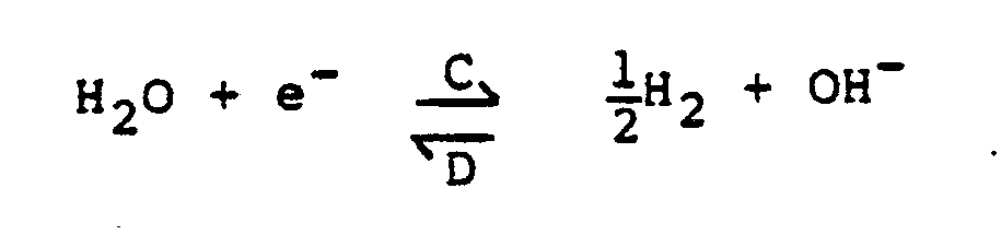

- Oxygen, generated in each unit cell at
nickel electrode 44 by electrolysis of the water in the aqueous electrolyte during the charging cycle, must be controlled, i.e. oxygen-hydrogen recombination, within the same unit cell of the bipolar battery. This same unit cell oxygen-hydrogen recombination is required in order to prevent imbalanced water distribution among unit cells which can cause performance imbalance among the unit cells. By way of illustration, inunit cell 12 all oxgyen evolved atnickel electrode 44 collects and passes through opening 58 innickel electrode 44 andseparator 42 tohydrogen electrode 40.Hydrogen electrode 40, withplatinum catalyst 41 thereon, provides an excellent media for oxygen recombination with gaseous hydrogen within the unit cell. Thus, all oxygen will be combined before it can reachhydrogen vent 56. - The confining and recombination of oxygen within the unit cell is important for long-life operation of the cell. If oxygen were to leave the unit cell and recombine in another location, water would effectively be transferred out of the unit cell into another unit cell. Water transfer between unit cells would result in electrolyte management problems, such as abundance of water in certain cells and a lack of water in other cells. If a unit cell lacks a sufficient amount of water therein, the dried-out cell would be unable to support the required electrochemical reaction.
- Another feature of the invention is the design of constraining
ring 54 which minimizes the electrolyte bridging between adjacent unit cells. Constrainingring 54 is constructed of a hydrophobic material, such as a hydrocarbon polymer that is at least partially fluorinated. Preferably, constrainingring 54 is constructed of a fluorocarbon polymer material such as polytetrafluoroethylene, to minimize electrolyte bridging between unit cells. With tight compression seals atjunctions rings 53 and 54), junction 61 (between constrainingring 53 and unit cell top end plate 50), junction 60 (between adjacent constrainingrings 54 and 55), and junction 62 (between constrainingring 54 and unit cell bottom end plate 52) to adjacent unit cells is minimized. - Each unit cell within
assembly 30 is oriented for axial current flow. Current flows in an axial direction through the electrodes, separators, screens, unit cell end plates, and cooling plates when provided. In cells having a radial current flow across the electrodes the potential drop along the radial direction may limit the size and thickness of the electrode. With an axial current flow through the unit cell, there are practically no such limitations in electrode dimensions as in cells which have the radial current flow. - The stacking of the unit cells thus defines a bipolar structure wherein serial cell connections are achieved by stacking unit cells with common end plates. An advantage of this type of structure for a large system, over batteries wherein current flows in a radial direction, is the potential light-weight aspects of the battery through elimination of many electrical tabs and leads.
- A bipolar nickel-hydrogen battery made of four unit cells of this invention was fabricated and cycle life tested to demonstrate over 4,000 cycles at 80% depth-of-discharge at ambient temperature. The battery contained four small size unit cells (30 cm² in area and 0.72 Amp-hr in capacity) without a cooling plate. Each unit cell was confined in a Teflon frame ("Teflon" being a tradename for a polytetrafluoroethylene material by DuPont Chemical Co. of Wilmington, Delaware) with a vent hole and two bipolar nickel plates or one bipolar plate and one end plate. Cell components were made of a nickel mesh gas screen, a porous conductor, a sintered-type nickel electrode with 2 millimeter size holes, a zirconia fabric separator, a hydrogen electrode (a standard type for an aerospace nickel-hydrogen cell), and 31% (by weight) aqueous KOH electrolyte. The battery was continuously cycled by discharging to 80% of its nominal capacity (0.72 Amphr.) in 17.5 minutes and recharging for 110% in 27.5 minutes. The battery was cycled for over 4,000 cycles before the end-of-discharge voltage dropped considerably below 4V.
- This invention has thus been described in its presently contemplated best mode and it is clear that it is susceptible to numerous modifications, modes and embodiments within the ability of those skilled in the art and without the exercise of the inventive faculty. Accordingly, the scope of this invention is defined by the scope of the following claims.
Claims (16)
- A bipolar nickel-hydrogen battery (10) comprising:(a) a pressure vessel (14) containing hydrogen gas; and(b) a plurality of unit cells located within said pressure vessels said unit cells (11, 12, 13, 15) being stacked adjacent one another wherein each unit cell comprises:(1) a hydrogen electrode (40) located within said cell space;(2) a positive electrode (44) located within said cell space having at least one opening (58) extending therethrough;(3) a gaspermeable separator (42) disposed between said positive and hydrogen electrodes (44, 40) within said cell space;(4) an electrolyte located in said cell space about said positive and hydrogen electrodes (44, 40) and said separator (42) to permit an electrochemical reaction between said positive and hydrogen electrodes (40, 44), characterized in that(5) said unit cells are connected in series along the axis of the stack for current flow through and between adjacent unit cells in an axial direction through the electrodes (40, 44) separators (42), screens (46), unit cell endplates (50, 52) and cooling plates (32, 34), when provided;(6) each unit cell comprises only one positive and one negative electrode (44, 40); the unit space of the cell is defined by electrically conductive unit cell top and bottom end plates (50 and 52) and a side wall (53, 54, 55) of a dielectric material; and said oxygen gas to be recombined with hydrogen gas to form water and said electrolyte are confined within each unit cell;(7) said positive electrode is a nickel electrode (44);(8) a porous electrical conductor (48) is located between said nickel electrode (44) and said bottom end plate (52);(9) said opening (58) extends through said positive electrode (44) to facilitate oxygen recombination by allowing oxygen gas evolved at said positive electrode (44) to reach said hydrogen electrode (40) for recombination with hydrogen gas thereat to form waters and(10) said gas permeable separator (42) allows oxygen evolved at said positive electrode (44) to reach said hydrogen electrode (49) for recombination with hydrogen gas thereat.
- The bipolar nickel-hydrogen battery of claim 1 wherein said separator (42) has top and bottom surfaces wherein at least one opening (58) extends through said separator top and bottom surfaces, and wherein said nickel electrode opening and said separator opening communicate to allow oxygen evolved from said nickel electrode (44) to flow through said nickel electrode opening and said separator opening to said hydrogen electrode (40) for recombination with hydrogen gas.
- The battery of claim 2 wherein said hydrogen electrode (40) is a porous graphite electrode having a porous platinum coating (41) on one side thereof with said porous platinum coating (41) facing said separator (42) so that said hydrogen electrode (40) separates said unit cell space into a unit cell electrolyte reservoir space on the side of said hydrogen electrode (40) having said porous platinum coating (41) thereon and a unit cell hydrogen gas space in the unit cell space on the side of said hydrogen electrode (40) away from said porous platinum coating.
- The battery of claim 3 wherein an electrically conductive gas screen (46) is positioned within said hydrogen gas space of said unit cell space.
- The battery of claim 2 wherein said nickel electrode (44) is a sintered nickel electrode.
- The battery of claim 1 wherein (a) said side wall (53, 54, 55) comprises a hydrophobic ring providing interior and exterior radial walls; (b) said top and bottom end plates (50, 52) are compression sealed on the top and bottom of said hydrophobic ring forming top and bottom walls, (c) said hydrophobic ring interior radial wall and said top and bottom walls form said unit cell space, (d) said unit cell first and second end plates (50, 52) are constructed of an electrically conductive metal with said unit cell first end plate (50) in electrical contact with said hydrogen electrode (40) through said gas screen (46), said gas screen (46) being in electrical contact with both said hydrogen electrode (40) and said unit cell first end plate (50), and (e) said hydrophobic ring (53, 54, 55) extends around the periphery of said unit cell first and second end plates (50, 52).
- The battery of claim 6 wherein a porous electrical conductor (48) is located between said nickel electrode (44) and said unit cell second end plate (52), said porous electrical conductor (48), being in electrical contact with said nickel electrode (44).
- The battery of claim 7 wherein said hydrophobic ring (53, 54, 55) contains a hydrogen vent (56) extending therethrough from said unit cell exterior into the interior of said unit cell at said unit cell hydrogen gas space so that hydrogen gas can flow between said unit cell exterior and said unit cell hydrogen gas space.
- The battery of claim 6 or 7 wherein said hydrophobic ring (53, 54, 55) comprises a hydrocarbon polymer that is at least partially fluorinated.
- The battery of claim 9 wherein said hydrophobic ring (53, 54, 55) comprises polytetrafluoroethylene.
- The battery of claim 6 wherein adjacent unit cells (11, 12 13, 15) share common unit cell first and second end plates (50, 52) and a plurality of unit cells form assemblies (30) of unit cells.
- The battery of claim 8 further comprising: cooling plates (32, 34) mounted on each of said assemblies (30); and coolant fluid tubes (26, 28) connected to said cooling plates (32, 34) so that coolant fluid may pass through said cooling plates to remove heat from said assemblies, said heat being generated by unit cell electrochemical reactions.
- A nickel-hydrogen bipolar battery according to claim 1 wherein(a) said pressure vessel (14) is a battery housing (14) having electrical lead throughs (18, 20) in said housing (14) and containing hydrogen gas therein;(b) said unit cells (11, 12, 13, 15) form an assembly stack (27) formed by a plurality of assemblies (30) stacked adjacent each other, wherein said assembly stack (27) has assembly first and second metallic end plates (36, 38) for collecting electricity form said assembly stack, said assembly first and second end plates (36, 38) have electrical connections (22, 24) thereto which extend out of said housing through said housing lead throughs (18, 20);(1) said side wall (53, 54, 55) is a hydrophobic dielectric member engaged with both of said unit cell end plates (50, 52) so as to hold said unit cell end plates in spaced relationship, thus forming walls that define a unit cell space between said end plates, said hydrophobic dielectric member having an opening (56) therethrough from said exterior and interior walls to allow hydrogen gas to flow between said unit cell space and said hydrophobic dielectric member exteriors;(2) said porous electrical conductor is contiguous said bottom end plate (52);(3) said sintered nickel electrode (44) is contiguous said porous conductor (48);(4) said porous conductor (48), said nickel electrode (44) and said separator (42) are partially filled with electrolyte;(5) hydrogen gas is located in a hydrogen space within said unit cell between said platinum coating (41) and said unit cell top end plate (50) and said electrolyte is located between said platinum coating and said unit cell bottom end plate (52).
- The battery of claim 13 wherein said electrolyte is an aqueous solution of potassium hydroxide.
- The battery of claim 13 wherein said sintered nickel electrode (44) is comprised of a hydroxide active material.
- The battery of claim 13 wherein said sintered nickel electrode (44) is comprised of a nickel oxide active material.
Applications Claiming Priority (2)
| Application Number | Priority Date | Filing Date | Title |
|---|---|---|---|
| US06/588,620 US4567119A (en) | 1984-03-12 | 1984-03-12 | Nickel-hydrogen bipolar battery |
| US588620 | 1984-03-12 |
Publications (2)
| Publication Number | Publication Date |
|---|---|
| EP0187145A1 EP0187145A1 (en) | 1986-07-16 |
| EP0187145B1 true EP0187145B1 (en) | 1991-03-06 |
Family
ID=24354608
Family Applications (1)
| Application Number | Title | Priority Date | Filing Date |
|---|---|---|---|
| EP19850901279 Expired - Lifetime EP0187145B1 (en) | 1984-03-12 | 1985-02-28 | Nickel-hydrogen bipolar battery |
Country Status (7)
| Country | Link |
|---|---|
| US (1) | US4567119A (en) |
| EP (1) | EP0187145B1 (en) |
| JP (1) | JPS61501352A (en) |
| KR (1) | KR890003874B1 (en) |
| DE (1) | DE3582043D1 (en) |
| IL (1) | IL74218A (en) |
| WO (1) | WO1985004287A1 (en) |
Cited By (3)
| Publication number | Priority date | Publication date | Assignee | Title |
|---|---|---|---|---|
| US7794877B2 (en) | 2005-05-03 | 2010-09-14 | Randy Ogg | Bi-polar rechargeable electrochemical battery |
| US8632901B2 (en) | 2007-10-26 | 2014-01-21 | G4 Synergetics, Inc. | Dish shaped and pressure equalizing electrodes for electrochemical batteries |
| US8859132B2 (en) | 2009-01-27 | 2014-10-14 | G4 Synergetics, Inc. | Variable volume containment for energy storage devices |
Families Citing this family (52)
| Publication number | Priority date | Publication date | Assignee | Title |
|---|---|---|---|---|
| US4706737A (en) * | 1986-11-20 | 1987-11-17 | International Fuel Cells Corporation | Fuel cell coolant inlet manifold and system |
| US4888256A (en) * | 1988-07-21 | 1989-12-19 | Westinghouse Electric Corp. | Separator |
| US5059496A (en) * | 1989-03-23 | 1991-10-22 | Globe-Union Inc. | Nickel-hydrogen battery with oxygen and electrolyte management features |
| DE3929306C2 (en) * | 1989-09-04 | 1997-04-17 | Varta Batterie | Gas-tight sealed metal oxide / hydrogen battery |
| CA2038354A1 (en) * | 1990-03-30 | 1991-10-01 | William H. Kelly | Ni-h2 battery having improved thermal properties |
| US5385793A (en) * | 1992-07-20 | 1995-01-31 | Globe-Union Inc. | Thermal management of battery systems |
| FR2694136B1 (en) * | 1992-07-27 | 1994-09-30 | Bertin & Cie | Electric storage battery equipped with cooling means and set of such batteries. |
| US5354630A (en) * | 1992-12-10 | 1994-10-11 | Comsat | Ni-H2 battery having improved thermal properties |
| DE4331763C1 (en) * | 1993-09-18 | 1994-11-10 | Friwo Silberkraft Ges Fuer Bat | Electrochemical actuator |
| US5393617A (en) * | 1993-10-08 | 1995-02-28 | Electro Energy, Inc. | Bipolar electrochmeical battery of stacked wafer cells |
| US5429888A (en) * | 1994-01-14 | 1995-07-04 | Space Systems/Loral, Inc. | Battery recharging technique |
| US5395706A (en) * | 1994-01-14 | 1995-03-07 | Space Systems/Loral, Inc. | Satellite battery thermal/capacity design |
| FR2745959B1 (en) | 1996-03-08 | 1998-07-10 | Sorapec Lab | IMPROVEMENTS IN OR RELATING TO THE NI-ZN ACCUMULATOR USING ANOLYTE, CATHOLYTE AND MEMBRANE FOR DENDRITE FORMATION |
| US5821009A (en) * | 1997-03-03 | 1998-10-13 | Space Systems/Loral, Inc. | Fault tolerant bipolar gas electrode design for a rechargeable battery |
| CA2237457A1 (en) * | 1997-05-19 | 1998-11-19 | Richard S. Bogner | Battery cell with spray-formed separator |
| US6054842A (en) * | 1998-07-24 | 2000-04-25 | The Boeing Company | Method for improving battery discharge performance |
| US5939864A (en) * | 1998-10-28 | 1999-08-17 | Space Systems/Loral, Inc. | Lithium-ion battery charge control method |
| DE19929950B4 (en) * | 1999-06-29 | 2004-02-26 | Deutsche Automobilgesellschaft Mbh | Bipolar stacked battery |
| DE10130369A1 (en) * | 2001-06-23 | 2003-01-02 | Behr Gmbh & Co | Device for cooling a vehicle device, in particular battery or fuel cell |
| US6503658B1 (en) * | 2001-07-11 | 2003-01-07 | Electro Energy, Inc. | Bipolar electrochemical battery of stacked wafer cells |
| US7045236B1 (en) | 2001-08-10 | 2006-05-16 | Johnson Controls Technology Company | Heat and gas exchange system for battery |
| JP2005506658A (en) * | 2001-10-09 | 2005-03-03 | エレクトラスター,エルエルシー | NiMH battery |
| JP4839955B2 (en) * | 2006-05-11 | 2011-12-21 | トヨタ自動車株式会社 | Battery pack and vehicle |
| US20090023061A1 (en) * | 2007-02-12 | 2009-01-22 | Randy Ogg | Stacked constructions for electrochemical batteries |
| US20100104927A1 (en) * | 2008-10-29 | 2010-04-29 | Scott Albright | Temperature-controlled battery configuration |
| US9028986B2 (en) | 2009-01-07 | 2015-05-12 | A123 Systems Llc | Fuse for battery cells |
| US8257848B2 (en) | 2009-01-12 | 2012-09-04 | A123 Systems, Inc. | Safety venting mechanism with tearing tooth structure for batteries |
| KR20120016252A (en) * | 2009-04-24 | 2012-02-23 | 지4 시너제틱스 인크. | Energy storage device with monopole and dipole cells electrically coupled in series and in parallel |
| EP2507891B1 (en) | 2009-12-04 | 2018-03-28 | A123 Systems LLC | Battery with integrated power management system and scalable battery cutoff component |
| FR3018396A1 (en) | 2014-03-04 | 2015-09-11 | Commissariat Energie Atomique | METHOD FOR MANUFACTURING ELECTROCHEMICAL ELECTROCHEMICAL CELL WITH ELECTRODE GAS OF THE METAL-GAS TYPE AND CELL THEREFOR |
| US11296361B2 (en) | 2015-07-07 | 2022-04-05 | Apple Inc. | Bipolar battery design |
| CN109690827A (en) | 2016-09-22 | 2019-04-26 | 苹果公司 | Current collector for stacked cell design |
| WO2018195372A1 (en) | 2017-04-21 | 2018-10-25 | Cougeller Research Llc | Battery cell with electrolyte diffusion material |
| WO2018213601A2 (en) | 2017-05-19 | 2018-11-22 | Cougeller Research Llc | Rechargeable battery with anion conducting polymer |
| US11018343B1 (en) | 2017-06-01 | 2021-05-25 | Apple Inc. | Current collector surface treatment |
| US10923728B1 (en) | 2017-06-16 | 2021-02-16 | Apple Inc. | Current collector structures for rechargeable battery |
| US10916741B1 (en) | 2017-08-08 | 2021-02-09 | Apple Inc. | Metallized current collector devices and materials |
| US11189834B1 (en) | 2017-08-09 | 2021-11-30 | Apple Inc. | Multiple electrolyte battery cells |
| KR102641151B1 (en) * | 2017-08-11 | 2024-02-28 | 더 보드 오브 트러스티스 오브 더 리랜드 스탠포드 쥬니어 유니버시티 | Metallic hydrogen batteries for large-scale energy storage |
| US11862801B1 (en) | 2017-09-14 | 2024-01-02 | Apple Inc. | Metallized current collector for stacked battery |
| US11335977B1 (en) | 2017-09-21 | 2022-05-17 | Apple Inc. | Inter-cell connection materials |
| US11043703B1 (en) | 2017-09-28 | 2021-06-22 | Apple Inc. | Stacked battery components and configurations |
| US11296351B1 (en) | 2018-01-12 | 2022-04-05 | Apple Inc. | Rechargeable battery with pseudo-reference electrode |
| US10916796B1 (en) | 2018-02-02 | 2021-02-09 | Apple Inc. | Selective charging matrix for rechargeable batteries |
| US11367877B1 (en) | 2018-09-19 | 2022-06-21 | Apple Inc. | Aqueous battery current collectors |
| US11588155B1 (en) | 2020-09-08 | 2023-02-21 | Apple Inc. | Battery configurations for cell balancing |
| US11677120B2 (en) | 2020-09-08 | 2023-06-13 | Apple Inc. | Battery configurations having through-pack fasteners |
| US11600891B1 (en) | 2020-09-08 | 2023-03-07 | Apple Inc. | Battery configurations having balanced current collectors |
| US11923494B2 (en) | 2020-09-08 | 2024-03-05 | Apple Inc. | Battery configurations having through-pack fasteners |
| JP7371657B2 (en) * | 2021-03-30 | 2023-10-31 | トヨタ自動車株式会社 | vehicle |
| DE102021110599A1 (en) | 2021-04-26 | 2022-10-27 | Fraunhofer-Gesellschaft zur Förderung der angewandten Forschung eingetragener Verein | ACCUMULATOR WITH BIPOLAR CONSTRUCTION |
| US11228065B1 (en) * | 2021-07-02 | 2022-01-18 | ZAF Energy Systems, Incorporated | Recombination systems for aqueous batteries |
Family Cites Families (14)
| Publication number | Priority date | Publication date | Assignee | Title |
|---|---|---|---|---|
| DE1050411B (en) * | 1959-02-12 | |||
| US3728158A (en) * | 1971-11-16 | 1973-04-17 | Gen Motors Corp | Low silhouette bi-polar battery |
| US3990910A (en) * | 1972-05-31 | 1976-11-09 | Tyco Laboratories, Inc. | Nickel-hydrogen battery |
| US3867199A (en) * | 1972-06-05 | 1975-02-18 | Communications Satellite Corp | Nickel hydrogen cell |
| US3964930A (en) * | 1975-07-21 | 1976-06-22 | United Technologies Corporation | Fuel cell cooling system |
| US4127703A (en) * | 1976-02-05 | 1978-11-28 | Eic Corporation | Nickel-hydrogen secondary battery |
| DE2637015C2 (en) * | 1976-08-17 | 1982-10-14 | Deutsche Automobilgesellschaft Mbh, 3000 Hannover | Nickel Oxide Hydrogen Cell |
| US4115630A (en) * | 1977-03-17 | 1978-09-19 | Communications Satellite Corporation | Metal-hydrogen battery |
| US4098962A (en) * | 1977-04-14 | 1978-07-04 | Yardney Electric Corporation | Metal-hydrogen secondary battery system |
| US4159367A (en) * | 1978-06-29 | 1979-06-26 | Yardney Electric Corporation | Hydrogen electrochemical cell and rechargeable metal-hydrogen battery |
| DE2835503C2 (en) * | 1978-08-12 | 1986-10-23 | Deutsche Automobilgesellschaft Mbh, 3000 Hannover | Nickel oxide / hydrogen cells with negative electrodes integrated into the diffusion body |
| US4327158A (en) * | 1980-08-15 | 1982-04-27 | Eic Laboratories, Inc. | Metal/gas battery |
| US4478918A (en) * | 1981-12-25 | 1984-10-23 | Tokyo Shibaura Denki Kabushiki Kaisha | Fuel cell stack |
| DE3218410A1 (en) * | 1982-05-15 | 1983-11-17 | Accumulatorenwerke Hoppecke Carl Zoellner & Sohn GmbH & Co KG, 5790 Brilon | GALVANIC ELEMENT, IN PARTICULAR METAL-AIR CELL |
-
1984
- 1984-03-12 US US06/588,620 patent/US4567119A/en not_active Expired - Lifetime
-
1985
- 1985-02-01 IL IL7421885A patent/IL74218A/en not_active IP Right Cessation
- 1985-02-28 WO PCT/US1985/000316 patent/WO1985004287A1/en not_active Ceased
- 1985-02-28 DE DE8585901279T patent/DE3582043D1/en not_active Expired - Fee Related
- 1985-02-28 JP JP60501107A patent/JPS61501352A/en active Granted
- 1985-02-28 KR KR1019850700294A patent/KR890003874B1/en not_active Expired
- 1985-02-28 EP EP19850901279 patent/EP0187145B1/en not_active Expired - Lifetime
Non-Patent Citations (2)
| Title |
|---|
| Chem. Abstracts vol 99 no. 22, 28.11.83 (Columbus Ohio US) R L Cataldo "Test results of a ten-cell bipolar nickel-hydrogen battery" p. 187, abstract no. 178996m * |
| Patent abstracts of Japan vol 7 no. 94,20.4.83 (E 171) (1239) * |
Cited By (3)
| Publication number | Priority date | Publication date | Assignee | Title |
|---|---|---|---|---|
| US7794877B2 (en) | 2005-05-03 | 2010-09-14 | Randy Ogg | Bi-polar rechargeable electrochemical battery |
| US8632901B2 (en) | 2007-10-26 | 2014-01-21 | G4 Synergetics, Inc. | Dish shaped and pressure equalizing electrodes for electrochemical batteries |
| US8859132B2 (en) | 2009-01-27 | 2014-10-14 | G4 Synergetics, Inc. | Variable volume containment for energy storage devices |
Also Published As
| Publication number | Publication date |
|---|---|
| WO1985004287A1 (en) | 1985-09-26 |
| IL74218A0 (en) | 1985-05-31 |
| US4567119A (en) | 1986-01-28 |
| JPS61501352A (en) | 1986-07-03 |
| DE3582043D1 (en) | 1991-04-11 |
| KR890003874B1 (en) | 1989-10-05 |
| EP0187145A1 (en) | 1986-07-16 |
| JPH0586634B2 (en) | 1993-12-13 |
| KR850700290A (en) | 1985-12-26 |
| IL74218A (en) | 1988-08-31 |
Similar Documents
| Publication | Publication Date | Title |
|---|---|---|
| EP0187145B1 (en) | Nickel-hydrogen bipolar battery | |
| US4159367A (en) | Hydrogen electrochemical cell and rechargeable metal-hydrogen battery | |
| US4839247A (en) | Static regenerative fuel cell system for use in space | |
| US4127703A (en) | Nickel-hydrogen secondary battery | |
| US3378406A (en) | Metal-oxygen-containing electro-chemical battery | |
| EP0290764B1 (en) | Cylindrical bipolar electrode battery | |
| EP0188873B1 (en) | Lightweight bipolar metal-gas battery | |
| US3975210A (en) | Metal-gas battery with axial reactant gas storage cavity | |
| US5059496A (en) | Nickel-hydrogen battery with oxygen and electrolyte management features | |
| US6806001B1 (en) | Battery in bipolar stacked configuration and method for the production thereof | |
| US3607403A (en) | Self-charging battery incorporating a solid-gas battery and storage battery within a honeycomb matrix | |
| EP3378116A1 (en) | Electrode assembly and flow battery with improved electrolyte distribution | |
| WO1996019015A2 (en) | Galvanic and fuel cell arrangements | |
| US4957830A (en) | Rechargeable metal oxide-hydrogen battery | |
| US3647542A (en) | Solid-fluid battery | |
| US4038461A (en) | Electrochemical cell having balanced distribution of oxygen and electrolyte | |
| US4546054A (en) | Support assembly for cells of a secondary battery | |
| EP0114484B1 (en) | Improved rechargeable lead-hydrogen electrical cell | |
| US3839091A (en) | Regenerative fuel cell | |
| US4614025A (en) | Method for making a lightweight bipolar metal-gas battery | |
| US3479225A (en) | Oxygen depolarized electrochemical modular units | |
| US4283468A (en) | Electrochemical cell insensitive to physical orientation | |
| JPH0744037B2 (en) | Activateable battery | |
| US4535038A (en) | Structure for electrochemical batteries | |
| EP0227830B1 (en) | Long life electrolyte for nickel-hydrogen cells |
Legal Events
| Date | Code | Title | Description |
|---|---|---|---|
| PUAI | Public reference made under article 153(3) epc to a published international application that has entered the european phase |
Free format text: ORIGINAL CODE: 0009012 |
|
| 17P | Request for examination filed |
Effective date: 19851028 |
|
| AK | Designated contracting states |
Kind code of ref document: A1 Designated state(s): CH DE GB LI NL |
|
| RAP1 | Party data changed (applicant data changed or rights of an application transferred) |
Owner name: HUGHES AIRCRAFT COMPANY |
|
| 17Q | First examination report despatched |
Effective date: 19870720 |
|
| GRAA | (expected) grant |
Free format text: ORIGINAL CODE: 0009210 |
|
| AK | Designated contracting states |
Kind code of ref document: B1 Designated state(s): CH DE GB LI NL |
|
| REF | Corresponds to: |
Ref document number: 3582043 Country of ref document: DE Date of ref document: 19910411 |
|
| PLBE | No opposition filed within time limit |
Free format text: ORIGINAL CODE: 0009261 |
|
| STAA | Information on the status of an ep patent application or granted ep patent |
Free format text: STATUS: NO OPPOSITION FILED WITHIN TIME LIMIT |
|
| 26N | No opposition filed | ||
| PGFP | Annual fee paid to national office [announced via postgrant information from national office to epo] |
Ref country code: GB Payment date: 19990119 Year of fee payment: 15 |
|
| PGFP | Annual fee paid to national office [announced via postgrant information from national office to epo] |
Ref country code: DE Payment date: 19990125 Year of fee payment: 15 |
|
| PGFP | Annual fee paid to national office [announced via postgrant information from national office to epo] |
Ref country code: NL Payment date: 19990126 Year of fee payment: 15 |
|
| PGFP | Annual fee paid to national office [announced via postgrant information from national office to epo] |
Ref country code: CH Payment date: 19990127 Year of fee payment: 15 |
|
| PG25 | Lapsed in a contracting state [announced via postgrant information from national office to epo] |
Ref country code: GB Free format text: LAPSE BECAUSE OF NON-PAYMENT OF DUE FEES Effective date: 20000228 |
|
| PG25 | Lapsed in a contracting state [announced via postgrant information from national office to epo] |
Ref country code: LI Free format text: LAPSE BECAUSE OF NON-PAYMENT OF DUE FEES Effective date: 20000229 Ref country code: CH Free format text: LAPSE BECAUSE OF NON-PAYMENT OF DUE FEES Effective date: 20000229 |
|
| PG25 | Lapsed in a contracting state [announced via postgrant information from national office to epo] |
Ref country code: NL Free format text: LAPSE BECAUSE OF NON-PAYMENT OF DUE FEES Effective date: 20000901 |
|
| REG | Reference to a national code |
Ref country code: CH Ref legal event code: PL |
|
| GBPC | Gb: european patent ceased through non-payment of renewal fee |
Effective date: 20000228 |
|
| NLV4 | Nl: lapsed or anulled due to non-payment of the annual fee |
Effective date: 20000901 |
|
| PG25 | Lapsed in a contracting state [announced via postgrant information from national office to epo] |
Ref country code: DE Free format text: LAPSE BECAUSE OF NON-PAYMENT OF DUE FEES Effective date: 20001201 |