EP0186973B1 - A weight monitoring system - Google Patents
A weight monitoring system Download PDFInfo
- Publication number
- EP0186973B1 EP0186973B1 EP85308626A EP85308626A EP0186973B1 EP 0186973 B1 EP0186973 B1 EP 0186973B1 EP 85308626 A EP85308626 A EP 85308626A EP 85308626 A EP85308626 A EP 85308626A EP 0186973 B1 EP0186973 B1 EP 0186973B1
- Authority
- EP
- European Patent Office
- Prior art keywords
- weight
- patient
- signal
- monitoring system
- time
- Prior art date
- Legal status (The legal status is an assumption and is not a legal conclusion. Google has not performed a legal analysis and makes no representation as to the accuracy of the status listed.)
- Expired - Lifetime
Links
- 238000012544 monitoring process Methods 0.000 title claims abstract description 54
- 238000011282 treatment Methods 0.000 claims abstract description 44
- 238000000502 dialysis Methods 0.000 claims abstract description 43
- 230000004580 weight loss Effects 0.000 claims abstract description 20
- 230000000007 visual effect Effects 0.000 claims abstract description 9
- 239000012530 fluid Substances 0.000 claims description 18
- 238000000034 method Methods 0.000 claims description 15
- 238000005303 weighing Methods 0.000 claims description 5
- 230000000694 effects Effects 0.000 claims 1
- 239000008280 blood Substances 0.000 description 5
- 210000004369 blood Anatomy 0.000 description 5
- 230000001276 controlling effect Effects 0.000 description 4
- 235000013305 food Nutrition 0.000 description 4
- 239000000126 substance Substances 0.000 description 4
- XLYOFNOQVPJJNP-UHFFFAOYSA-N water Substances O XLYOFNOQVPJJNP-UHFFFAOYSA-N 0.000 description 4
- 238000001631 haemodialysis Methods 0.000 description 2
- 239000012528 membrane Substances 0.000 description 2
- 230000003247 decreasing effect Effects 0.000 description 1
- 238000001914 filtration Methods 0.000 description 1
- 239000007788 liquid Substances 0.000 description 1
- 239000000463 material Substances 0.000 description 1
- 230000000737 periodic effect Effects 0.000 description 1
- 230000002250 progressing effect Effects 0.000 description 1
- 230000001105 regulatory effect Effects 0.000 description 1
- 230000000717 retained effect Effects 0.000 description 1
- 230000004584 weight gain Effects 0.000 description 1
- 235000019786 weight gain Nutrition 0.000 description 1
Images

Classifications
-
- G—PHYSICS
- G01—MEASURING; TESTING
- G01G—WEIGHING
- G01G19/00—Weighing apparatus or methods adapted for special purposes not provided for in the preceding groups
- G01G19/44—Weighing apparatus or methods adapted for special purposes not provided for in the preceding groups for weighing persons
- G01G19/445—Weighing apparatus or methods adapted for special purposes not provided for in the preceding groups for weighing persons in a horizontal position
-
- A—HUMAN NECESSITIES
- A61—MEDICAL OR VETERINARY SCIENCE; HYGIENE
- A61M—DEVICES FOR INTRODUCING MEDIA INTO, OR ONTO, THE BODY; DEVICES FOR TRANSDUCING BODY MEDIA OR FOR TAKING MEDIA FROM THE BODY; DEVICES FOR PRODUCING OR ENDING SLEEP OR STUPOR
- A61M1/00—Suction or pumping devices for medical purposes; Devices for carrying-off, for treatment of, or for carrying-over, body-liquids; Drainage systems
- A61M1/14—Dialysis systems; Artificial kidneys; Blood oxygenators ; Reciprocating systems for treatment of body fluids, e.g. single needle systems for hemofiltration or pheresis
- A61M1/16—Dialysis systems; Artificial kidneys; Blood oxygenators ; Reciprocating systems for treatment of body fluids, e.g. single needle systems for hemofiltration or pheresis with membranes
-
- A—HUMAN NECESSITIES
- A61—MEDICAL OR VETERINARY SCIENCE; HYGIENE
- A61M—DEVICES FOR INTRODUCING MEDIA INTO, OR ONTO, THE BODY; DEVICES FOR TRANSDUCING BODY MEDIA OR FOR TAKING MEDIA FROM THE BODY; DEVICES FOR PRODUCING OR ENDING SLEEP OR STUPOR
- A61M1/00—Suction or pumping devices for medical purposes; Devices for carrying-off, for treatment of, or for carrying-over, body-liquids; Drainage systems
- A61M1/14—Dialysis systems; Artificial kidneys; Blood oxygenators ; Reciprocating systems for treatment of body fluids, e.g. single needle systems for hemofiltration or pheresis
- A61M1/16—Dialysis systems; Artificial kidneys; Blood oxygenators ; Reciprocating systems for treatment of body fluids, e.g. single needle systems for hemofiltration or pheresis with membranes
- A61M1/1601—Control or regulation
- A61M1/1603—Regulation parameters
- A61M1/1611—Weight of the patient
-
- G—PHYSICS
- G01—MEASURING; TESTING
- G01G—WEIGHING
- G01G23/00—Auxiliary devices for weighing apparatus
- G01G23/18—Indicating devices, e.g. for remote indication; Recording devices; Scales, e.g. graduated
- G01G23/36—Indicating the weight by electrical means, e.g. using photoelectric cells
- G01G23/365—Indicating the weight by electrical means, e.g. using photoelectric cells involving comparison with a reference value
-
- G—PHYSICS
- G01—MEASURING; TESTING
- G01G—WEIGHING
- G01G23/00—Auxiliary devices for weighing apparatus
- G01G23/18—Indicating devices, e.g. for remote indication; Recording devices; Scales, e.g. graduated
- G01G23/36—Indicating the weight by electrical means, e.g. using photoelectric cells
- G01G23/37—Indicating the weight by electrical means, e.g. using photoelectric cells involving digital counting
- G01G23/3707—Indicating the weight by electrical means, e.g. using photoelectric cells involving digital counting using a microprocessor
- G01G23/3721—Indicating the weight by electrical means, e.g. using photoelectric cells involving digital counting using a microprocessor with particular representation of the result, e.g. graphic
-
- Y—GENERAL TAGGING OF NEW TECHNOLOGICAL DEVELOPMENTS; GENERAL TAGGING OF CROSS-SECTIONAL TECHNOLOGIES SPANNING OVER SEVERAL SECTIONS OF THE IPC; TECHNICAL SUBJECTS COVERED BY FORMER USPC CROSS-REFERENCE ART COLLECTIONS [XRACs] AND DIGESTS
- Y10—TECHNICAL SUBJECTS COVERED BY FORMER USPC
- Y10S—TECHNICAL SUBJECTS COVERED BY FORMER USPC CROSS-REFERENCE ART COLLECTIONS [XRACs] AND DIGESTS
- Y10S128/00—Surgery
- Y10S128/13—Infusion monitoring
Definitions
- This invention relates to a weight monitoring system. More particularly, this invention relates to a weight monitoring system for a scale. Still more particularly, this invention relates to a weight monitoring system for use with a patient undergoing a dialysis treatment.
- a dialysis treatment it is generally required that a patient lose a predetermined amount of weight over a given period of time.
- a dialysis patient is usually subjected to a dialysis treatment wherein his blood is continuously passed through a dialysis machine in order to remove water and chemicals from the blood stream.
- dialysis treatments have been carried out over shorter periods of time, for example over a four hour period during which a predetermined weight loss is obtained.
- the period of time is usually established as the minimum for removing water and chemicals from a patient so as to bring the patient to a weight which has been previously determined as his desired weight.
- the amount of weight loss is presumed to be equivalent to the amount of water and chemicals which have to be removed from his body.
- the dialysis machines which have been available to dialyize a patient over a four hour period have usually been programmed so as to remove a certain rate of fluids over a period of time.
- the membrane or filtering equipment which has been used in these machines to withdraw fluids from a blood stream can vary in the rate of removal not only during treatment but also from one treatment to the next should the membrane or filters be of a reusable type.
- an attendant usually checks the weight of the patient from time to time during treatment to determine whether or not the patient will reach the desired weight at the end of the treatment time. For example, if the attendant determines that the weight loss is too slow, the dialysis machine is adjusted to increase the rate of fluid withdrawal.
- US-A-4,324,663 discloses a method and apparatus for regulating haemodialysis conditions.
- the apparatus includes means for calculating curves which define the limits of the range of acceptable weights of a patient at any given time during haemodialysis, and means for displaying these limits and the actual measured weight of the patient.
- a weight monitoring system for use with a scale, said system comprising first means for receiving an actual weight signal from a weighing scale having a load thereon undergoing a change in weight with time, and a second means for generating a signal corresponding to a desired programmed weight; characterised in that the system further comprises a comparator connected to said first means and said second means for receiving and comparing the actual weight signal and said programmed weight signal to produce an error signal indicative of a difference therebetween; and a visual read-out means for simultaneously displaying a chronological sequence of said error signals.
- This system is preferably used in combination with a scale having means for emitting an output signal corresponding to an actual weight of the patient.
- a method of monitoring the weight of a patient undergoing a change in weight said method being characterised by the steps of: generating a first signal corresponding to an actual weight of the patient at predetermined intervals of time during treatment; generating a second signal corresponding to a desired programmed weight for the patient at each interval of time; comparing said first signal with said second signal at each interval of time to obtain an error signal indicative of a difference between said first and second signals; and displaying at each interval of time, a chronological sequence of error signals.
- the first means may be in the form of an analog to digital converter for converting an analog signal from the scale which is indicative of actual weight into a digital signal.
- the comparator is in the form of a digital comparator.
- the read-out means preferably comprises a screen for graphically displaying the chronological sequence of the error signals. This is of importance since the read-out means may then provide a trend indicator of the deviations of the actual weight from the programmed or ideal weight over time. For example, if an attendant notes that a sequence of error signals are of the same value over a given period of time, no adjustment need be made in the treatment. On the other hand, if a sequence of error signals indicates a trend to increasing errors, a change can be made in the treatment so as to reduce the values of subsequent error signals.
- the weight monitoring system is particularly useful in monitoring the weight of a dialysis patient.
- the monitoring system can be connected to and between a scale which weighs the patient and produces an output signal corresponding to the actual weight and a dialysis unit which includes means for controlling the rate of withdrawal of the fluids from the patient.
- the dialysis unit can be programmed in known manner to withdraw fluids from the patient at a predetermined rate so as to achieve a certain nominal or desired weight of the patient at the end of a given period of time.
- the monitoring system is then able to compare the actual weight of the patient on the scale with the programmed weight for that instant of elapsed time to obtain and display any difference between the weights in an automatic manner. By displaying a chronological sequence of error signals along with the magnitude of each, an attendant can quickly and visually determine a trend in the treatment and make adjustments in the dialysis machine if necessary.
- the monitoring system includes a programmer which receives a signal corresponding to the desired weight loss for a patient as well as a signal corresponding to the desired time of treatment.
- the programmer can be suitably programmed so as to produce a signal equal to the starting weight less the amount of weight which should have been lost at the elapsed time. This resulting signal is then used as the programmed weight signal for comparison in the comparator.
- the error signals may also be used to control the rate of withdrawal of fluids in the dialysis unit.
- the monitoring system would be connected to the control means in the dialysis unit in order to automatically adjust the control means in response to an error signal.
- the control means may be continuously adjusted by a series of error signals.
- the weight monitoring system 10 is employed with a scale 11 and a dialysis unit 12.
- the scale 11 is of a type such as described in U.S. patent 4,281,730 which is suitable for weighing a bed-ridden patient.
- the scale 11 includes two platforms 12 for receiving the head and foot, respectively of a bed 13.
- the platforms 12 are, in turn, electrically connected by suitable lines 14 to the monitoring system 10 in order to deliver signals thereto indicative of the weight of a load on the scale 11.
- the weight signals may be emitted in the form of a DC signal such that 100 kilograms will produce a DC signal of 1.000 volts.
- the weight monitoring system 10 includes a suitable means for generating a signal corresponding to the weight change of a load on the scale 11.
- any suitable circuit may be provided to receive the weight signal from the scale 11 and to convert the signal, from analog to digital form.
- the circuit may be actuated at predetermined intervals of time in order to provide a chronological sequence of readings.
- the monitoring system 10 is also provided with a means for generating a signal corresponding to the lapse of time within a given period of treatment time.
- a means for generating a signal corresponding to the lapse of time within a given period of treatment time.
- any suitable timing circuit can be used to generate the signal.
- the signal may be of digital form.
- the dialysis unit may be of any suitable known type which can be connected to a patient for withdrawing fluid from the blood stream of a patient on the bed 13.
- such dialysis units include control means for controlling the rate of withdrawal of fluids from the blood stream of a patient.
- the monitoring system 10 can be connected with the dialysis unit 12 via an electrical line 23 for automatically controlling the rate of withdrawal effected by the dialysis unit 12.
- the desired wieght of a patient to be treated is first determined. Thereafter, the patient is positioned on the bed 13 and an actual weight is determined via the scale 11 and a sutiable read-out (not shown). The difference between the two weights is then used as the desired weight loss to be obtained during dialysis treatment. This information is then fed into the monitoring system. In addition, the time of treatment is determined and this information is also inputted to the monitoring system. The dialysis unit 12 can then be connected in the usual fashion and treatment started. At the same time, the monitoring system 10 would be activated, for example via a suitable start switch.
- the weight of the patient would gradually reduce in a continuous manner. If the monitoring system 10 is programmed to function at predetermined time intervals, an actual weight signal is obtained from the scale 11 at these intervals of time and a corresponding signal is generated within the monitoring system 10. At the same time, the monitoring system generates a signal indicating the elapsed time.
- the rate monitoring system may also be connected between a scale 31, for example of the type described in U.S. Patent 4,023,633 wherein a patient can be seated in a chair (not shown), such as a lounge chair, which is, in turn, mounted on the scale 31.
- the monitoring system 30 can be positioned adjacent to the chair and provided with a read-out means 32 for an instantaneous read-out.
- the total weight of the patient before treatment can be recorded on the read-out means.
- This weight may then be tared out, for example at the scale or at the read-out, so that a zero reading or other suitable standard is obtained. Thereafter, as treatment progresses, any fluctuations in the weight of the patient from the standard can be monitored in the monitoring system 10.
- the monitoring system 30 is connected to a dialysis unit 33 to automatically adjust the dialysis unit 33.
- the scale 31 is provided with suitable means such as an LVDT driver and demodulator for generating a signal indicative of the weight loss by a patient.
- This signal can then be directed via a suitable line 34 to the read-out 32.
- the signal can be emitted via a line 35 to the monitoring system 30.
- the signal can be emitted so that a 0.001 volt signal value corresponds to 0.1 kilograms.
- the monitoring system 30 has a means in the form of an analog to digital converter 36 for receiving the actual weight signal from the scale 31 via the line 35.
- the converter 36 then generates a corresponding signal for delivery to a comparator 37 which is connected thereto via a suitable line 38.
- the monitoring system 30 has an input means 39 for receiving a signal corresponding to a desired weight change and a second input means 40 for receiving a signal corresponding to a period of time over which the weight change is to occur.
- These inputs 39, 40 are connected to a programmer 41 within which the information received is able to emit a programmed rate signal (PR) via a line 42 to the comparator 37.
- PR programmed rate signal
- the desired weight loss (TL) can be obtained by a simple subtraction.
- the desired rate (DR) of weight loss for example in grams per hour can be * obtained by dividing the desired weight loss (DL) by the time of dialysis treatment (DT) multiplied by 1000. Again, this calculation can be carried out within the programmer.
- the programmed weight (PR) can be obtained by subtracting from the starting weight (SW) the desired weight loss (DL) for the elapsed time (ET) during the treatment time (DT). Again, this can be suitably programmed within the programmer 41.
- the comparator 37 is of digital type and is connected to the converter 36 and the programmer 41 in order to receive and compare the actual weight signal delivered via the line 38 and the programmed weight signal delivered via the line 42 and to produce an error signal via a line 43 in response to a difference between the actual weight signal and the programmed weight signal.
- This error signal can be produced at periodic intervals of time during treatment or can be produced on a continuous basis.
- the monitoring system also has a visual read-out means 44 for displaying a chronological sequence of the error signals.
- the read-out means 44 is connected to the line 43 and is suitably programmed to visually indicate the value of the error signal at given intervals of time during the treatment program.
- a suitable display 45 is also provided to visually indicate the value of the error signal emitted via the line 43.
- the read-out means 44 includes a display screen 46 for graphically displaying a chronological sequence of the error signals.
- the graph shows a time line 47 on an X-axis while the error signals are emitted at predetermined intervals of time at values which are measured along a Y-axis.
- a chronological sequence of error signals 48 are illustrated which are of different values. For example, the first two error signals are of the same value. This indicates that the weight of the patient differs from the programmed weight by the same amount. The next two succeeding signals indicate that the difference is increasing while the next four signals indicate that the differences have decreased.
- the pattern of error signals indicated in Fig. 2 shows by negative values that the patient is initially losing weight at a faster rate than the programmed or desired rate but that the patients weight is gradually brought back to the programmed rate to finish at the desired weight.
- the visual display provides a trend indicator by which an attendant can visually determine whether or not a patient is progressing along at a suitable rate equal to or close to the rate of programmed decrease.
- the graph can be retained for historical purposes.
- the error signal can be emitted via the line 43 directly to the dialysis unit 33.
- the dialysis unit 33 includes a means in the form of a controller 49 for controlling the rate of withdrawal of fluids from a patient 50.
- the controller 49 is controlled by a motor controller 51 such as a DC stepper motor.
- the error signal can be emitted overthe line 43 directlyto the motor 51 so as to speed up or slow down a motor and, thus, the controller 49 so as to increase or decrease, respectively, the rate of withdrawal of fluids from the patient 50.
- the motor can be adjusted manually by an attendant without using automatic controls.
- a patient 50 can be placed on the chair which is mounted on the scale 31 and an initial weight reading taken.
- the desired target weight (DW) and the desired dialysis time (DT) can be fed into the programmer 41 of the monitoring system 30.
- the monitored system 30 can then monitor the actual weight losses which occur against the programmed weight throughout the treatment time while producing a visual display of any differences.
- a suitable power supply 52 is connected to the scale 31 and the converter 36 and comparator 37 of the monitoring system 30.
- the method of monitoring the weight of a patient undergoing a change in weight treatment comprises the simple steps of generating a first signal corresponding to an actual change in weight of the patient at at least one point in time during the treatment, generating a second signal corresponding to an elapse of time of the treatment and displaying the signals to obtain a visual comparison of the change in weight relative to the elaspedtime.
- a method can be readily carried out in the embodiment as illustrated in Fig. 1.
- the signals can be displayed in bar form and in parallel relation and may also be continuously displayed during the time of treatment.
- the method of monitoring the weight of a patient may be carried out in a manner as indicated in Fig. 2.
- a first signal is generated corresponding to an actual weight of the patient at predetermined intervals of time during treatment.
- This signal is then compared with a second signal corresponding to a desired programmed weight for the patient at each interval of time so as to obtain an error signal in response to a difference between the two received signals.
- This error signal can then be displayed at each interval of time, for example graphically and in chronological sequence.
- the invention thus provides a monitoring system and a method of monitoring which is relatively simple and which can continuously indicate to an attendant whether or not a patient is losing weight at a programmed weight.
- the invention provides an embodiment wherein a dialysis unit or the like can be adjusted so as to adjust the rate ofwithdrawal of fluids from a patient in dependance upon the programmed weight actually obtained.
- the invention permits a patient being treated to consume fluids or food or to pick up a book.
- an unusual error signal would be produced on the read-out display, for example as indicated in Fig. 2.
- An attendant can thereafter tear out the weight which has been added or, in the case of food, may speed up the dialysis treatment in order to reduce the weight of the patient by the amount of fluids or food which have been consumed.
Landscapes
- Health & Medical Sciences (AREA)
- Urology & Nephrology (AREA)
- Heart & Thoracic Surgery (AREA)
- General Physics & Mathematics (AREA)
- Engineering & Computer Science (AREA)
- Physics & Mathematics (AREA)
- Anesthesiology (AREA)
- General Health & Medical Sciences (AREA)
- Veterinary Medicine (AREA)
- Vascular Medicine (AREA)
- Public Health (AREA)
- Biomedical Technology (AREA)
- Hematology (AREA)
- Life Sciences & Earth Sciences (AREA)
- Animal Behavior & Ethology (AREA)
- Emergency Medicine (AREA)
- Computer Hardware Design (AREA)
- Microelectronics & Electronic Packaging (AREA)
- External Artificial Organs (AREA)
- Emergency Alarm Devices (AREA)
- Testing And Monitoring For Control Systems (AREA)
- Flow Control (AREA)
- Vibration Prevention Devices (AREA)
Abstract
Description
- This invention relates to a weight monitoring system. More particularly, this invention relates to a weight monitoring system for a scale. Still more particularly, this invention relates to a weight monitoring system for use with a patient undergoing a dialysis treatment.
- As is known, there are many types of treatment which require that a patient undergo a weight loss or a weight gain during treatment. For example, in the case of a dialysis treatment, it is generally required that a patient lose a predetermined amount of weight over a given period of time. In this regard, a dialysis patient is usually subjected to a dialysis treatment wherein his blood is continuously passed through a dialysis machine in order to remove water and chemicals from the blood stream.
- In the past, patients were connected to dialysis machines for periods of time which were considered to be sufficient to remove sufficient water and chemicals, for example for eight or more hours of time. However, these treatments required the patients to be confined to a fixed location such as a bed for excessive periods of time.
- In more recent times, dialysis treatments have been carried out over shorter periods of time, for example over a four hour period during which a predetermined weight loss is obtained. In these cases, the period of time is usually established as the minimum for removing water and chemicals from a patient so as to bring the patient to a weight which has been previously determined as his desired weight. The amount of weight loss is presumed to be equivalent to the amount of water and chemicals which have to be removed from his body.
- The dialysis machines which have been available to dialyize a patient over a four hour period have usually been programmed so as to remove a certain rate of fluids over a period of time. However, the membrane or filtering equipment which has been used in these machines to withdraw fluids from a blood stream can vary in the rate of removal not only during treatment but also from one treatment to the next should the membrane or filters be of a reusable type. To ensure that a patient is losing weight at an appropriate rate, an attendant usually checks the weight of the patient from time to time during treatment to determine whether or not the patient will reach the desired weight at the end of the treatment time. For example, if the attendant determines that the weight loss is too slow, the dialysis machine is adjusted to increase the rate of fluid withdrawal. If the weight loss appears to be too fast, the machine is slowed. However, such a technique requires several readings to be made by an attendant over the time period in order to make a determination as to the weight loss in the patient. Further this can be complicated should the patient consume any foods or liquids during treatment since this would increase the patient's weight. Also, should the patient pick up a book or other reading material during a weighing operation, such might also give a spurious weight reading.
- Where dialysis treatment is carried out over a short period of time, use has frequently been made of a scale and chair arrangement wherein the patient is seated in a chair of comfortable contour with the chair, in turn, mounted on a scale platform so that weight readings can be obtained of the patient from time to time.
- In summary, the techniques which have been employed to date for monitoring the weight loss of a dialysis patient have been tedious and time consuming. Further, in many cases, the techniques have not been accurate.
- US-A-4,324,663 discloses a method and apparatus for regulating haemodialysis conditions. The apparatus includes means for calculating curves which define the limits of the range of acceptable weights of a patient at any given time during haemodialysis, and means for displaying these limits and the actual measured weight of the patient.
- Accordingly, it is an object of the invention to accurately monitor the weight loss of a patient undergoing dialysis treatment.
- It is another object of the invention to be able to change the rate of fluid withdrawal from a dialysis patient during treatment in order to secure a programmed rate of weight change.
- It is another object of the invention to provide a relatively simple monitoring system for monitoring the weight loss of a patient undergoing a change of weight treatment.
- It is another object of the invention to provide a monitoring system which provides a visual read-out of changes in a programmed rate of fluid withdrawal in a dialysis patient.
- It is another object of the invention to provide a method of monitoring a weight loss of a patient in a simple manner.
- According to a first aspect of the present invention, there is provided a weight monitoring system for use with a scale, said system comprising first means for receiving an actual weight signal from a weighing scale having a load thereon undergoing a change in weight with time, and a second means for generating a signal corresponding to a desired programmed weight; characterised in that the system further comprises a comparator connected to said first means and said second means for receiving and comparing the actual weight signal and said programmed weight signal to produce an error signal indicative of a difference therebetween; and a visual read-out means for simultaneously displaying a chronological sequence of said error signals.
- This system is preferably used in combination with a scale having means for emitting an output signal corresponding to an actual weight of the patient.
- According to a second aspect of the present invention, there is provided a method of monitoring the weight of a patient undergoing a change in weight, said method being characterised by the steps of: generating a first signal corresponding to an actual weight of the patient at predetermined intervals of time during treatment; generating a second signal corresponding to a desired programmed weight for the patient at each interval of time; comparing said first signal with said second signal at each interval of time to obtain an error signal indicative of a difference between said first and second signals; and displaying at each interval of time, a chronological sequence of error signals.
- For example, the first means may be in the form of an analog to digital converter for converting an analog signal from the scale which is indicative of actual weight into a digital signal. In this case, the comparator is in the form of a digital comparator.
- The read-out means preferably comprises a screen for graphically displaying the chronological sequence of the error signals. This is of importance since the read-out means may then provide a trend indicator of the deviations of the actual weight from the programmed or ideal weight over time. For example, if an attendant notes that a sequence of error signals are of the same value over a given period of time, no adjustment need be made in the treatment. On the other hand, if a sequence of error signals indicates a trend to increasing errors, a change can be made in the treatment so as to reduce the values of subsequent error signals.
- The weight monitoring system is particularly useful in monitoring the weight of a dialysis patient. For example, the monitoring system can be connected to and between a scale which weighs the patient and produces an output signal corresponding to the actual weight and a dialysis unit which includes means for controlling the rate of withdrawal of the fluids from the patient. During use, the dialysis unit can be programmed in known manner to withdraw fluids from the patient at a predetermined rate so as to achieve a certain nominal or desired weight of the patient at the end of a given period of time. The monitoring system is then able to compare the actual weight of the patient on the scale with the programmed weight for that instant of elapsed time to obtain and display any difference between the weights in an automatic manner. By displaying a chronological sequence of error signals along with the magnitude of each, an attendant can quickly and visually determine a trend in the treatment and make adjustments in the dialysis machine if necessary.
- In order to obtain a signal corresponding to the programmed weight for the patient, the monitoring system includes a programmer which receives a signal corresponding to the desired weight loss for a patient as well as a signal corresponding to the desired time of treatment. With another signal being directed to the programmer which corresponds to the starting weight of the patient and with another signal corresponding to the elapsed time of treatment, the programmer can be suitably programmed so as to produce a signal equal to the starting weight less the amount of weight which should have been lost at the elapsed time. This resulting signal is then used as the programmed weight signal for comparison in the comparator.
- In addition to obtaining a visual read-out of a sequence of error signals, the error signals may also be used to control the rate of withdrawal of fluids in the dialysis unit. In this respect, the monitoring system would be connected to the control means in the dialysis unit in order to automatically adjust the control means in response to an error signal. Furthermore, the control means may be continuously adjusted by a series of error signals.
- These and other objects and advantages of the invention will become more apparent from the following detailed description taken in conjunction with the accompanying drawings wherein:
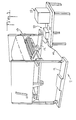
- Fig. 1 illustrates a schematic view of a weight monitoring system employed with a dialysis unit and a scale for receiving a bed; and
- Fig. 2 illustrates a diagrammatic view of a monitoring system in combination with a scale and a dialysis unit.
- Referring to Fig. 1, the
weight monitoring system 10 is employed with ascale 11 and adialysis unit 12. As indicated, thescale 11 is of a type such as described in U.S. patent 4,281,730 which is suitable for weighing a bed-ridden patient. To this end, thescale 11 includes twoplatforms 12 for receiving the head and foot, respectively of abed 13. Theplatforms 12 are, in turn, electrically connected by suitable lines 14 to themonitoring system 10 in order to deliver signals thereto indicative of the weight of a load on thescale 11. For example, the weight signals may be emitted in the form of a DC signal such that 100 kilograms will produce a DC signal of 1.000 volts. - The
weight monitoring system 10 includes a suitable means for generating a signal corresponding to the weight change of a load on thescale 11. To this end, any suitable circuit may be provided to receive the weight signal from thescale 11 and to convert the signal, from analog to digital form. In addition, the circuit may be actuated at predetermined intervals of time in order to provide a chronological sequence of readings. - The
monitoring system 10 is also provided with a means for generating a signal corresponding to the lapse of time within a given period of treatment time. To this end, any suitable timing circuit can be used to generate the signal. Again, the signal may be of digital form. - Referring to Fig. 1, the dialysis unit may be of any suitable known type which can be connected to a patient for withdrawing fluid from the blood stream of a patient on the
bed 13. As is known, such dialysis units include control means for controlling the rate of withdrawal of fluids from the blood stream of a patient. As indicated in Fig. 1, themonitoring system 10 can be connected with thedialysis unit 12 via anelectrical line 23 for automatically controlling the rate of withdrawal effected by thedialysis unit 12. - In use, the desired wieght of a patient to be treated is first determined. Thereafter, the patient is positioned on the
bed 13 and an actual weight is determined via thescale 11 and a sutiable read-out (not shown). The difference between the two weights is then used as the desired weight loss to be obtained during dialysis treatment. This information is then fed into the monitoring system. In addition, the time of treatment is determined and this information is also inputted to the monitoring system. Thedialysis unit 12 can then be connected in the usual fashion and treatment started. At the same time, themonitoring system 10 would be activated, for example via a suitable start switch. - As the patient is being treated, the weight of the patient would gradually reduce in a continuous manner. If the
monitoring system 10 is programmed to function at predetermined time intervals, an actual weight signal is obtained from thescale 11 at these intervals of time and a corresponding signal is generated within themonitoring system 10. At the same time, the monitoring system generates a signal indicating the elapsed time. - Referring to Fig. 2, the rate monitoring system may also be connected between a
scale 31, for example of the type described in U.S. Patent 4,023,633 wherein a patient can be seated in a chair (not shown), such as a lounge chair, which is, in turn, mounted on thescale 31. In such a situation, the monitoring system 30 can be positioned adjacent to the chair and provided with a read-out means 32 for an instantaneous read-out. For example, with a patient seated in the chair initially, the total weight of the patient before treatment can be recorded on the read-out means. This weight may then be tared out, for example at the scale or at the read-out, so that a zero reading or other suitable standard is obtained. Thereafter, as treatment progresses, any fluctuations in the weight of the patient from the standard can be monitored in themonitoring system 10. - As also indicated in Fig. 2, the monitoring system 30 is connected to a dialysis unit 33 to automatically adjust the dialysis unit 33.
- As indicated in Fig. 2, the
scale 31 is provided with suitable means such as an LVDT driver and demodulator for generating a signal indicative of the weight loss by a patient. This signal can then be directed via asuitable line 34 to the read-out 32. At the same time, the signal can be emitted via a line 35 to the monitoring system 30. For example, the signal can be emitted so that a 0.001 volt signal value corresponds to 0.1 kilograms. - The monitoring system 30 has a means in the form of an analog to digital converter 36 for receiving the actual weight signal from the
scale 31 via the line 35. The converter 36 then generates a corresponding signal for delivery to acomparator 37 which is connected thereto via asuitable line 38. - In addition, the monitoring system 30 has an input means 39 for receiving a signal corresponding to a desired weight change and a second input means 40 for receiving a signal corresponding to a period of time over which the weight change is to occur. These
inputs 39, 40 are connected to aprogrammer 41 within which the information received is able to emit a programmed rate signal (PR) via aline 42 to thecomparator 37. - For example, obtaining the starting weight (SW) of a patient and subtracting the desired weight (TW), i.e. the dry target weight, the desired weight loss (TL) can be obtained by a simple subtraction. Further, the desired rate (DR) of weight loss, for example in grams per hour can be* obtained by dividing the desired weight loss (DL) by the time of dialysis treatment (DT) multiplied by 1000. Again, this calculation can be carried out within the programmer.
- The programmed weight (PR) can be obtained by subtracting from the starting weight (SW) the desired weight loss (DL) for the elapsed time (ET) during the treatment time (DT). Again, this can be suitably programmed within the
programmer 41. - The
comparator 37 is of digital type and is connected to the converter 36 and theprogrammer 41 in order to receive and compare the actual weight signal delivered via theline 38 and the programmed weight signal delivered via theline 42 and to produce an error signal via aline 43 in response to a difference between the actual weight signal and the programmed weight signal. This error signal can be produced at periodic intervals of time during treatment or can be produced on a continuous basis. - The monitoring system also has a visual read-out means 44 for displaying a chronological sequence of the error signals. In this regard, the read-out means 44 is connected to the
line 43 and is suitably programmed to visually indicate the value of the error signal at given intervals of time during the treatment program. Asuitable display 45 is also provided to visually indicate the value of the error signal emitted via theline 43. - As indicated in Fig. 2, the read-out means 44 includes a display screen 46 for graphically displaying a chronological sequence of the error signals. As indicated, the graph shows a
time line 47 on an X-axis while the error signals are emitted at predetermined intervals of time at values which are measured along a Y-axis. In the illustrated display, a chronological sequence of error signals 48 are illustrated which are of different values. For example, the first two error signals are of the same value. This indicates that the weight of the patient differs from the programmed weight by the same amount. The next two succeeding signals indicate that the difference is increasing while the next four signals indicate that the differences have decreased. - The pattern of error signals indicated in Fig. 2 shows by negative values that the patient is initially losing weight at a faster rate than the programmed or desired rate but that the patients weight is gradually brought back to the programmed rate to finish at the desired weight. As such, the visual display provides a trend indicator by which an attendant can visually determine whether or not a patient is progressing along at a suitable rate equal to or close to the rate of programmed decrease. At the end of a treatment, the graph can be retained for historical purposes.
- As indicated in Fig. 2, the error signal can be emitted via the
line 43 directly to the dialysis unit 33. In this respect, the dialysis unit 33 includes a means in the form of acontroller 49 for controlling the rate of withdrawal of fluids from a patient 50. In addition, thecontroller 49 is controlled by amotor controller 51 such as a DC stepper motor. The error signal can be emitted overtheline 43 directlyto themotor 51 so as to speed up or slow down a motor and, thus, thecontroller 49 so as to increase or decrease, respectively, the rate of withdrawal of fluids from the patient 50. Alternatively, the motor can be adjusted manually by an attendant without using automatic controls. - In use, a patient 50 can be placed on the chair which is mounted on the
scale 31 and an initial weight reading taken. At the same time, the desired target weight (DW) and the desired dialysis time (DT) can be fed into theprogrammer 41 of the monitoring system 30. Once activated, the monitored system 30 can then monitor the actual weight losses which occur against the programmed weight throughout the treatment time while producing a visual display of any differences. - As indicated in Fig. 2, a
suitable power supply 52 is connected to thescale 31 and the converter 36 andcomparator 37 of the monitoring system 30. - The method of monitoring the weight of a patient undergoing a change in weight treatment comprises the simple steps of generating a first signal corresponding to an actual change in weight of the patient at at least one point in time during the treatment, generating a second signal corresponding to an elapse of time of the treatment and displaying the signals to obtain a visual comparison of the change in weight relative to the elaspedtime. Such a method can be readily carried out in the embodiment as illustrated in Fig. 1. In this respect, the signals can be displayed in bar form and in parallel relation and may also be continuously displayed during the time of treatment.
- Alternatively, the method of monitoring the weight of a patient may be carried out in a manner as indicated in Fig. 2. In this respect, a first signal is generated corresponding to an actual weight of the patient at predetermined intervals of time during treatment. This signal is then compared with a second signal corresponding to a desired programmed weight for the patient at each interval of time so as to obtain an error signal in response to a difference between the two received signals. This error signal can then be displayed at each interval of time, for example graphically and in chronological sequence.
- The invention thus provides a monitoring system and a method of monitoring which is relatively simple and which can continuously indicate to an attendant whether or not a patient is losing weight at a programmed weight.
- Further, the invention provides an embodiment wherein a dialysis unit or the like can be adjusted so as to adjust the rate ofwithdrawal of fluids from a patient in dependance upon the programmed weight actually obtained.
- Further, the invention permits a patient being treated to consume fluids or food or to pick up a book. In these cases, an unusual error signal would be produced on the read-out display, for example as indicated in Fig. 2. An attendant can thereafter tear out the weight which has been added or, in the case of food, may speed up the dialysis treatment in order to reduce the weight of the patient by the amount of fluids or food which have been consumed.
Claims (11)
Priority Applications (1)
| Application Number | Priority Date | Filing Date | Title |
|---|---|---|---|
| AT85308626T ATE51446T1 (en) | 1984-11-28 | 1985-11-27 | WEIGHT MONITORING SYSTEM. |
Applications Claiming Priority (2)
| Application Number | Priority Date | Filing Date | Title |
|---|---|---|---|
| US06/675,833 US4629015A (en) | 1984-11-28 | 1984-11-28 | Weight monitoring system |
| US675833 | 1984-11-28 |
Publications (3)
| Publication Number | Publication Date |
|---|---|
| EP0186973A2 EP0186973A2 (en) | 1986-07-09 |
| EP0186973A3 EP0186973A3 (en) | 1987-04-29 |
| EP0186973B1 true EP0186973B1 (en) | 1990-03-28 |
Family
ID=24712141
Family Applications (1)
| Application Number | Title | Priority Date | Filing Date |
|---|---|---|---|
| EP85308626A Expired - Lifetime EP0186973B1 (en) | 1984-11-28 | 1985-11-27 | A weight monitoring system |
Country Status (6)
| Country | Link |
|---|---|
| US (1) | US4629015A (en) |
| EP (1) | EP0186973B1 (en) |
| JP (1) | JPS61228313A (en) |
| AT (1) | ATE51446T1 (en) |
| CA (1) | CA1237522A (en) |
| DE (1) | DE3576849D1 (en) |
Cited By (1)
| Publication number | Priority date | Publication date | Assignee | Title |
|---|---|---|---|---|
| US7264730B2 (en) | 1991-04-19 | 2007-09-04 | Baxter International Inc. | Methods for kidney dialysis |
Families Citing this family (74)
| Publication number | Priority date | Publication date | Assignee | Title |
|---|---|---|---|---|
| CH661796A5 (en) * | 1985-01-17 | 1987-08-14 | Scaime | APPARATUS FOR MEASURING AND RECORDING FORCES. |
| FR2593951B1 (en) * | 1986-02-03 | 1989-01-06 | Bertin & Cie | METHOD AND SYSTEM FOR REMOTE CONTROL OF AT LEAST ONE INFUSION STATION |
| WO1988007836A1 (en) * | 1987-04-08 | 1988-10-20 | Georg-August-Universität Göttingen | Process and arrangement for the determination of the chronobiological activities of an experimental animal (''göttinger cbm chronobiometer'') |
| US4844187A (en) * | 1988-08-15 | 1989-07-04 | Jabero Thair F | Future weight machine |
| US4899839A (en) * | 1989-06-14 | 1990-02-13 | Dessertine Albert L | Compliance and patient status monitoring system and method |
| GB2235776A (en) * | 1989-08-10 | 1991-03-13 | Univ London | Measuring the fluid balance of a patient during surgery |
| US5172781A (en) * | 1989-10-27 | 1992-12-22 | Kinetic Concepts, Inc. | Scale for fluidized bed and method for using same |
| WO1992012490A1 (en) * | 1991-01-11 | 1992-07-23 | Health Innovations, Inc. | Method and apparatus to control diet and weight using human behavior modification techniques |
| US5326476A (en) * | 1991-04-19 | 1994-07-05 | Althin Medical, Inc. | Method and apparatus for kidney dialysis using machine with programmable memory |
| US5346472A (en) * | 1993-06-02 | 1994-09-13 | Baxter International Inc. | Apparatus and method for preventing hypotension in a dialysis patient |
| US5788851A (en) * | 1995-02-13 | 1998-08-04 | Aksys, Ltd. | User interface and method for control of medical instruments, such as dialysis machines |
| IT1279572B1 (en) * | 1995-05-30 | 1997-12-16 | Hospal Dasco Spa | METHOD AND APPARATUS FOR WASHING A FILTER FOR DIALYSIS. |
| IT1276468B1 (en) * | 1995-07-04 | 1997-10-31 | Hospal Dasco Spa | AUTOMATIC DIALYSIS METHOD AND EQUIPMENT |
| US20010044588A1 (en) * | 1996-02-22 | 2001-11-22 | Mault James R. | Monitoring system |
| US5859390A (en) * | 1996-10-23 | 1999-01-12 | Hill-Rom, Inc. | Hospital bed scale mounting apparatus |
| US5853377A (en) * | 1997-04-17 | 1998-12-29 | Nestec S.A. | System and method for monitoring and analyzing dynamic nutritional status in patients with chronic disease |
| EP1217942A1 (en) | 1999-09-24 | 2002-07-03 | Healthetech, Inc. | Physiological monitor and associated computation, display and communication unit |
| US6924441B1 (en) | 1999-09-29 | 2005-08-02 | Hill-Rom Services, Inc. | Load cell apparatus |
| US6478736B1 (en) | 1999-10-08 | 2002-11-12 | Healthetech, Inc. | Integrated calorie management system |
| AU1350101A (en) * | 1999-10-29 | 2001-05-14 | Strategic Visualization, Inc. | Apparatus and method for providing medical services over a communication network |
| US6336136B1 (en) * | 1999-12-24 | 2002-01-01 | Scott C. Harris | Internet weight reduction system |
| US6513532B2 (en) * | 2000-01-19 | 2003-02-04 | Healthetech, Inc. | Diet and activity-monitoring device |
| US6482158B2 (en) | 2000-05-19 | 2002-11-19 | Healthetech, Inc. | System and method of ultrasonic mammography |
| AU2001265022A1 (en) * | 2000-05-25 | 2001-12-03 | Healthetech, Inc. | Physiological monitoring using wrist-mounted device |
| JP2004503887A (en) * | 2000-06-16 | 2004-02-05 | ヘルセテック インコーポレイテッド | Speech recognition device for portable information terminals |
| US6607387B2 (en) | 2000-10-30 | 2003-08-19 | Healthetech, Inc. | Sensor system for diagnosing dental conditions |
| US20030208409A1 (en) * | 2001-04-30 | 2003-11-06 | Mault James R. | Method and apparatus for diet control |
| US20030130567A1 (en) * | 2002-01-09 | 2003-07-10 | Mault James R. | Health-related devices and methods |
| US20030130595A1 (en) * | 2001-08-13 | 2003-07-10 | Mault James R. | Health improvement systems and methods |
| FR2833078B1 (en) * | 2001-11-30 | 2005-01-07 | Seb Sa | APPARATUS FOR MEASURING A BIOLOGICAL PARAMETER WITH A GRAPHICAL REPRESENTATION DISPLAY |
| US20030152607A1 (en) * | 2002-02-13 | 2003-08-14 | Mault James R. | Caloric management system and method with voice recognition |
| DE10256741B3 (en) * | 2002-12-05 | 2004-07-01 | Dr.Ing.H.C. F. Porsche Ag | Seat console for a vehicle seat |
| US6816807B2 (en) * | 2003-01-23 | 2004-11-09 | Kriger Yefim G | Hidden overweight preventing system and method |
| US8029454B2 (en) | 2003-11-05 | 2011-10-04 | Baxter International Inc. | High convection home hemodialysis/hemofiltration and sorbent system |
| US7465272B2 (en) * | 2004-02-12 | 2008-12-16 | Yefim Kriger | Vehicle with on-board dieters' self-acquiring overweight preventive system and method |
| US7170016B2 (en) * | 2004-07-09 | 2007-01-30 | Dumornay Jean D | Body mass related risk factor scale |
| US7253366B2 (en) | 2004-08-09 | 2007-08-07 | Hill-Rom Services, Inc. | Exit alarm for a hospital bed triggered by individual load cell weight readings exceeding a predetermined threshold |
| US7176391B2 (en) * | 2004-09-13 | 2007-02-13 | Hill-Rom Services, Inc. | Load cell to frame interface for hospital bed |
| US20060149301A1 (en) * | 2005-01-05 | 2006-07-06 | Claus Michael J | Phacoemulsification system utilizing graphical user interfaces for adjusting pulse parameters |
| US8226595B2 (en) | 2006-05-26 | 2012-07-24 | Baxter International Inc. | Automated dialysis system driven by gravity and vacuum |
| JP5320691B2 (en) * | 2007-06-11 | 2013-10-23 | オムロンヘルスケア株式会社 | Weight scale |
| US20090075781A1 (en) * | 2007-09-18 | 2009-03-19 | Sensei, Inc. | System for incorporating data from biometric devices into a feedback message to a mobile device |
| US8882668B2 (en) | 2007-11-19 | 2014-11-11 | Elizabeth S. Thompson | Method and process for body composition management |
| US8262602B2 (en) * | 2008-06-02 | 2012-09-11 | Baxter International Inc. | Remote exchange peritoneal dialysis |
| US9514283B2 (en) | 2008-07-09 | 2016-12-06 | Baxter International Inc. | Dialysis system having inventory management including online dextrose mixing |
| US8057679B2 (en) | 2008-07-09 | 2011-11-15 | Baxter International Inc. | Dialysis system having trending and alert generation |
| US7981281B2 (en) * | 2008-07-09 | 2011-07-19 | Baxter International, Inc. | Dialysis system having regimen generation methodology |
| IT1391086B1 (en) * | 2008-07-09 | 2011-11-18 | Gambro Lundia Ab | EXTRACORPOREO BLOOD TREATMENT SYSTEM |
| US8062513B2 (en) | 2008-07-09 | 2011-11-22 | Baxter International Inc. | Dialysis system and machine having therapy prescription recall |
| US8168063B2 (en) * | 2008-07-09 | 2012-05-01 | Baxter International Inc. | Dialysis system having filtering method for determining therapy prescriptions |
| US8255225B2 (en) * | 2008-08-07 | 2012-08-28 | Vocollect Healthcare Systems, Inc. | Voice assistant system |
| US8282829B2 (en) | 2009-05-20 | 2012-10-09 | Baxter International Inc. | System and method for automated data collection of twenty-four hour ultrafiltration and other patient parameters using wired or wireless technology |
| US8926551B2 (en) * | 2009-07-07 | 2015-01-06 | Baxter Healthcare Inc. | Peritoneal dialysis therapy with large dialysis solution volumes |
| US8717181B2 (en) | 2010-07-29 | 2014-05-06 | Hill-Rom Services, Inc. | Bed exit alert silence with automatic re-enable |
| US20120111643A1 (en) * | 2010-11-05 | 2012-05-10 | Ralf Lindner | Method and apparatus for weighing a person |
| DE102011010067A1 (en) * | 2011-02-01 | 2012-08-02 | Fresenius Medical Care Deutschland Gmbh | Method and device for controlling an extracorporeal blood treatment device |
| JP5853534B2 (en) * | 2011-09-26 | 2016-02-09 | オムロンヘルスケア株式会社 | Weight management device |
| EP2711036B1 (en) | 2012-09-21 | 2015-12-30 | Gambro Lundia AB | An apparatus control for extracorporeal blood treatment |
| DE102012109861A1 (en) * | 2012-10-16 | 2014-04-17 | B. Braun Avitum Ag | Patient scale with camera monitoring and dialysis therapy system with camera-monitored weighing procedure |
| US10292605B2 (en) | 2012-11-15 | 2019-05-21 | Hill-Rom Services, Inc. | Bed load cell based physiological sensing systems and methods |
| JP2015109891A (en) * | 2013-12-06 | 2015-06-18 | セイコーエプソン株式会社 | Information processing apparatus and information processing method |
| EP2995242B1 (en) | 2014-09-11 | 2023-11-15 | Hill-Rom S.A.S. | Patient support apparatus |
| US11541205B2 (en) | 2015-07-20 | 2023-01-03 | Roivios Limited | Coated urinary catheter or ureteral stent and method |
| US12064567B2 (en) | 2015-07-20 | 2024-08-20 | Roivios Limited | Percutaneous urinary catheter |
| US10918827B2 (en) | 2015-07-20 | 2021-02-16 | Strataca Systems Limited | Catheter device and method for inducing negative pressure in a patient's bladder |
| CN112691278B (en) | 2015-07-20 | 2024-03-22 | 罗维奥斯有限公司 | Ureter and bladder catheter and method of introducing negative pressure to increase renal perfusion |
| US11040172B2 (en) | 2015-07-20 | 2021-06-22 | Strataca Systems Limited | Ureteral and bladder catheters and methods of inducing negative pressure to increase renal perfusion |
| US10926062B2 (en) | 2015-07-20 | 2021-02-23 | Strataca Systems Limited | Ureteral and bladder catheters and methods of inducing negative pressure to increase renal perfusion |
| US10512713B2 (en) * | 2015-07-20 | 2019-12-24 | Strataca Systems Limited | Method of removing excess fluid from a patient with hemodilution |
| US10493232B2 (en) | 2015-07-20 | 2019-12-03 | Strataca Systems Limited | Ureteral catheters, bladder catheters, systems, kits and methods for inducing negative pressure to increase renal function |
| WO2019038730A1 (en) | 2017-08-25 | 2019-02-28 | Strataca Systems Limited | Indwelling pump for facilitating removal of urine from the urinary tract |
| WO2019169034A1 (en) | 2018-02-27 | 2019-09-06 | Delp Stella K | Systems and methods that provide a positive experience during weight management |
| US12527524B2 (en) | 2020-03-30 | 2026-01-20 | Hill-Rom Services, Inc. | Bed-based ballistocardiogram apparatus and method |
| US12472301B2 (en) | 2021-08-13 | 2025-11-18 | 3Ive Labs, Llc | Negative pressure therapy system and methods |
Citations (1)
| Publication number | Priority date | Publication date | Assignee | Title |
|---|---|---|---|---|
| US4200896A (en) * | 1977-08-26 | 1980-04-29 | Mettler Instrument Ag | Method and system for controlling a multi-segment indicator to furnish an analogue display indicating only the relationship of the measured value to a desired value or range of values |
Family Cites Families (6)
| Publication number | Priority date | Publication date | Assignee | Title |
|---|---|---|---|---|
| FR2366023A1 (en) * | 1976-07-30 | 1978-04-28 | Inst Nat Sante Rech Med | METHOD AND APPARATUS FOR ADJUSTING THE CONDITIONS OF HEMODIALYSIS |
| JPS5945085B2 (en) * | 1977-08-08 | 1984-11-02 | 日機装株式会社 | Weight measurement bed |
| JPS6019250B2 (en) * | 1977-11-09 | 1985-05-15 | 日機装株式会社 | Improvement of medical beds |
| US4318447A (en) * | 1979-12-18 | 1982-03-09 | Northcutt Michael E | Diet scale with weight progress indicator |
| US4301879A (en) * | 1980-02-27 | 1981-11-24 | Dubow Arnold A | Body weight scale with historical record display |
| JPS57161511A (en) * | 1981-03-30 | 1982-10-05 | Takemoto Denki Keiki Kk | Controlling method for measurement and recording of patient's weight |
-
1984
- 1984-11-28 US US06/675,833 patent/US4629015A/en not_active Expired - Lifetime
-
1985
- 1985-11-27 AT AT85308626T patent/ATE51446T1/en not_active IP Right Cessation
- 1985-11-27 DE DE8585308626T patent/DE3576849D1/en not_active Expired - Fee Related
- 1985-11-27 EP EP85308626A patent/EP0186973B1/en not_active Expired - Lifetime
- 1985-11-28 CA CA000496447A patent/CA1237522A/en not_active Expired
- 1985-11-28 JP JP60268235A patent/JPS61228313A/en active Pending
Patent Citations (1)
| Publication number | Priority date | Publication date | Assignee | Title |
|---|---|---|---|---|
| US4200896A (en) * | 1977-08-26 | 1980-04-29 | Mettler Instrument Ag | Method and system for controlling a multi-segment indicator to furnish an analogue display indicating only the relationship of the measured value to a desired value or range of values |
Cited By (4)
| Publication number | Priority date | Publication date | Assignee | Title |
|---|---|---|---|---|
| US7264730B2 (en) | 1991-04-19 | 2007-09-04 | Baxter International Inc. | Methods for kidney dialysis |
| US7303680B2 (en) | 1991-04-19 | 2007-12-04 | Baxter International Inc. | Method and apparatus for kidney dialysis |
| US7318892B2 (en) | 1991-04-19 | 2008-01-15 | Baxter International Inc. | Method and apparatus for kidney dialysis |
| US7351340B2 (en) | 1991-04-19 | 2008-04-01 | Baxter International Inc. | Methods for providing kidney dialysis equipment and services |
Also Published As
| Publication number | Publication date |
|---|---|
| US4629015A (en) | 1986-12-16 |
| DE3576849D1 (en) | 1990-05-03 |
| EP0186973A2 (en) | 1986-07-09 |
| JPS61228313A (en) | 1986-10-11 |
| CA1237522A (en) | 1988-05-31 |
| ATE51446T1 (en) | 1990-04-15 |
| EP0186973A3 (en) | 1987-04-29 |
Similar Documents
| Publication | Publication Date | Title |
|---|---|---|
| US4629015A (en) | Weight monitoring system | |
| US4324663A (en) | Method and apparatus for regulating haemodialysis conditions | |
| DE69619448T2 (en) | Blood Pressure Monitor | |
| US4869266A (en) | Patient monitoring unit for surgical use | |
| US4326513A (en) | Patient data controlled respiration system | |
| US4776333A (en) | Ventilator with variable flow pattern | |
| DE69017507T2 (en) | Electronic sphygmomanometer. | |
| EP0428505B2 (en) | A control apparatus | |
| DE60204883T3 (en) | Control for a blood treatment device | |
| US4968295A (en) | Method of separating the constituents of the blood | |
| EP0260259B1 (en) | A method and an apparatus for automatically tuning a process regulator | |
| US6579241B2 (en) | Dialysis apparatus using a blood pressure meter and a controller | |
| US20110077575A1 (en) | Blood treatment device | |
| EP0611228A2 (en) | Technique for extracorporeal treatment of blood | |
| US4539843A (en) | Altimeter and vertical speed indicator | |
| US4614178A (en) | Automatic dose meter and control circuit arrangement | |
| WO1993001845A1 (en) | Method of monitoring a dialysis unit | |
| GB2153081A (en) | Regulating glucose level in blood stream | |
| US20030073950A1 (en) | Method for setting up a dialysis treament in a dialysis machine | |
| DE69607566T2 (en) | AUTOMATIC SPHYGMOMANOMETER | |
| EP0535449B1 (en) | Air flow control apparatus and method for an automatic blood pressure gauge | |
| EP1207923B2 (en) | Dialysis machine comprising a devce for setting up a dialysis treatment | |
| GB2052303A (en) | Dialysis apparatus | |
| KR900005492B1 (en) | Tieline control | |
| JPH07132141A (en) | Dialysis system |
Legal Events
| Date | Code | Title | Description |
|---|---|---|---|
| PUAI | Public reference made under article 153(3) epc to a published international application that has entered the european phase |
Free format text: ORIGINAL CODE: 0009012 |
|
| AK | Designated contracting states |
Kind code of ref document: A2 Designated state(s): AT BE CH DE FR GB IT LI NL SE |
|
| PUAL | Search report despatched |
Free format text: ORIGINAL CODE: 0009013 |
|
| AK | Designated contracting states |
Kind code of ref document: A3 Designated state(s): AT BE CH DE FR GB IT LI NL SE |
|
| 17P | Request for examination filed |
Effective date: 19871022 |
|
| 17Q | First examination report despatched |
Effective date: 19871214 |
|
| RAP1 | Party data changed (applicant data changed or rights of an application transferred) |
Owner name: KINETIC CONCEPTS, INC. |
|
| GRAA | (expected) grant |
Free format text: ORIGINAL CODE: 0009210 |
|
| AK | Designated contracting states |
Kind code of ref document: B1 Designated state(s): AT BE CH DE FR GB IT LI NL SE |
|
| PG25 | Lapsed in a contracting state [announced via postgrant information from national office to epo] |
Ref country code: SE Effective date: 19900328 Ref country code: LI Effective date: 19900328 Ref country code: CH Effective date: 19900328 Ref country code: BE Effective date: 19900328 Ref country code: AT Effective date: 19900328 |
|
| REF | Corresponds to: |
Ref document number: 51446 Country of ref document: AT Date of ref document: 19900415 Kind code of ref document: T |
|
| ITF | It: translation for a ep patent filed | ||
| REF | Corresponds to: |
Ref document number: 3576849 Country of ref document: DE Date of ref document: 19900503 |
|
| ET | Fr: translation filed | ||
| REG | Reference to a national code |
Ref country code: CH Ref legal event code: PL |
|
| PLBE | No opposition filed within time limit |
Free format text: ORIGINAL CODE: 0009261 |
|
| STAA | Information on the status of an ep patent application or granted ep patent |
Free format text: STATUS: NO OPPOSITION FILED WITHIN TIME LIMIT |
|
| 26N | No opposition filed | ||
| ITPR | It: changes in ownership of a european patent |
Owner name: CESSIONE;KINETIC CONCEPTS MANUFACTURING, INC. |
|
| REG | Reference to a national code |
Ref country code: FR Ref legal event code: TP |
|
| ITTA | It: last paid annual fee | ||
| REG | Reference to a national code |
Ref country code: GB Ref legal event code: 732 |
|
| NLS | Nl: assignments of ep-patents |
Owner name: KINETIC CONCEPTS MANUFACTURING, INC. TE SAN ANTONI |
|
| PGFP | Annual fee paid to national office [announced via postgrant information from national office to epo] |
Ref country code: DE Payment date: 19941123 Year of fee payment: 10 |
|
| PGFP | Annual fee paid to national office [announced via postgrant information from national office to epo] |
Ref country code: FR Payment date: 19941124 Year of fee payment: 10 |
|
| PGFP | Annual fee paid to national office [announced via postgrant information from national office to epo] |
Ref country code: NL Payment date: 19941130 Year of fee payment: 10 |
|
| PG25 | Lapsed in a contracting state [announced via postgrant information from national office to epo] |
Ref country code: NL Effective date: 19960601 |
|
| PG25 | Lapsed in a contracting state [announced via postgrant information from national office to epo] |
Ref country code: FR Effective date: 19960731 |
|
| NLV4 | Nl: lapsed or anulled due to non-payment of the annual fee |
Effective date: 19960601 |
|
| PG25 | Lapsed in a contracting state [announced via postgrant information from national office to epo] |
Ref country code: DE Effective date: 19960801 |
|
| REG | Reference to a national code |
Ref country code: FR Ref legal event code: ST |
|
| PGFP | Annual fee paid to national office [announced via postgrant information from national office to epo] |
Ref country code: GB Payment date: 20010504 Year of fee payment: 16 |
|
| PG25 | Lapsed in a contracting state [announced via postgrant information from national office to epo] |
Ref country code: GB Free format text: LAPSE BECAUSE OF NON-PAYMENT OF DUE FEES Effective date: 20011127 |
|
| REG | Reference to a national code |
Ref country code: GB Ref legal event code: IF02 |
|
| GBPC | Gb: european patent ceased through non-payment of renewal fee |
Effective date: 20011127 |