EP0186179A2 - Display apparatus - Google Patents
Display apparatus Download PDFInfo
- Publication number
- EP0186179A2 EP0186179A2 EP85116478A EP85116478A EP0186179A2 EP 0186179 A2 EP0186179 A2 EP 0186179A2 EP 85116478 A EP85116478 A EP 85116478A EP 85116478 A EP85116478 A EP 85116478A EP 0186179 A2 EP0186179 A2 EP 0186179A2
- Authority
- EP
- European Patent Office
- Prior art keywords
- fluorescent lamp
- liquid crystal
- crystal display
- display
- display apparatus
- Prior art date
- Legal status (The legal status is an assumption and is not a legal conclusion. Google has not performed a legal analysis and makes no representation as to the accuracy of the status listed.)
- Withdrawn
Links
Images


Classifications
-
- G—PHYSICS
- G09—EDUCATION; CRYPTOGRAPHY; DISPLAY; ADVERTISING; SEALS
- G09F—DISPLAYING; ADVERTISING; SIGNS; LABELS OR NAME-PLATES; SEALS
- G09F9/00—Indicating arrangements for variable information in which the information is built-up on a support by selection or combination of individual elements
- G09F9/30—Indicating arrangements for variable information in which the information is built-up on a support by selection or combination of individual elements in which the desired character or characters are formed by combining individual elements
- G09F9/35—Indicating arrangements for variable information in which the information is built-up on a support by selection or combination of individual elements in which the desired character or characters are formed by combining individual elements being liquid crystals
Definitions
- the present invention relates to a display apparatus comprising a plurality of display units each having a fluorescent lamp and a liquid crystal display element, and fluorescent lamp stabilizers connected to the fluorescent lamps, respectively, and, more particularly, to a display apparatus having a compact construction in which the fluorescent lamp stabilizers are incorporated into the display units, respectively.
- a liquid crystal display element 2 a case 3 holding the liquid crystal display element 2
- a flexible circuit board 4 which transmits a signal for driving the liquid crystal display element 2
- a fluorescent lamp 5 disposed behind the liquid crystal display element 2 for irradiating the liquid crystal display element 2
- a socketed harness 6 for connecting the fluorescent lamp to a power source
- a connector 6a a cable 6b
- a connector A 6c for connecting the liquid crystal display apparatus, namely, a large picture display apparatus, to the power source of the fluorescent lamp
- a backboard 7 for controlling the signal to be given to the liquid crystal display element 2
- a connector B 7a provided on the backboard 7 for transmitting control signals to the large picture display apparatus.
- a box 8 accommodating a plurality of the liquid crystal display units 1, stabilizer cabinets 9 accommodating fluorescent lamp stabilizers, not shown, and glow lamps, not shown, connection cable 10 connecting the stabilizer cabinets 9 to the liquid crystal display units 1, and a power source which supplies power to the fluorescent lamp stabilizers, not shown, accommodated in the stabilizer cabinets 9.
- Fig. 6 is a sectional view of the liquid crystal display unit 1 taken along line VI-VI of Fig. 4.
- reflecting plate 3a for reflecting the light emitted by the fluorescent lamp 5
- diffusion plate 3b disposed within the case 3 for uniformly diffusing the light emitted by the fluorescent lamp 5
- glass plate 3c incorporated into the case 3 so as to hold the liquid crystal display element 2.
- the conventional liquid crystal display unit 1 is constituted as illustrated in Figs. 4 to 6.
- the light emitted by the fluorescent lamp 5 is reflected by the reflecting plate 3a, and then falls on the liquid crystal display element 2 after being uniformly diffused by the diffusion plate 3b.
- a control signal for controlling the image on the large picture display apparatus is given through the connector B 7a to the backboard 7, and then is transmitted through the flexible circuit board 4 to the liquid crystal display element 2 to drive the liquid crystal display element 2.
- the transmissivity of the liquid crystal display element 2 hence the contents of display on the surface of the liquid crystal display element 2., changes according to the control signal.
- the large picture display apparatus has a large display surface consisting of the liquid crystal display units 1 each being capable of changing the contents of display in the above-mentioned manner.
- the stabilizers and glow lamps for lighting the fluorescent lamps are disposed apart from the principal unit of the liquid crystal display apparatus in separate units. Therefore, an additional space is necessary for accommodating the stabilizers and glow lamps. Furthermore, since the stabilizers and the glow lamps are disposed apart from the principal unit of the liquid crystal display apparatus, many long cables are necessary for connecting the stabilizers and the glow lamps to the corresponding fluorescent lamps 5. Consequently, the interior of the liquid crystal display apparatus is crowded with the complicated arrangement of the long cables and the associated parts, and hence the cables transmitting high-voltage power are liable to generate noises that causes troubles in the electronic circuits of the liquid crystal display units 1.
- a display apparatus including a plurality of display units each provided with a fluorescent lamp stabilizer disposed within the case thereof, having a short cable for connecting the fluorescent lamp stabilizer to the fluorescent lamp to reduce noises generated by the cable, and capable of displaying images of improved quality.
- the fluorescent lamp stabilizer of each liquid crystal display unit is disposed within the case of the liquid crystal display unit and connected to'the fluorescent lamp with a short cable. Accordingly, noises attributable to the current flowing through long cables are reduced and the liquid crystal display apparatus can be formed in a compact construction, because any additional space for accommodating the fluo - rescent lamp stabilizers is unnecessary.
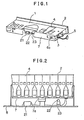
- Fig. 1 there are shown a fluorescent lamp stabilizer 21 held within a case 3, and a glow lamp 22 and a glow lamp holder 23 forming a fluorescent lamp circuit and disposed within the case 3.
- a fluorescent lamp 5 is lighted by the agency of the glow lamp 22 to irradiate a liquid crystal display element 2.
- a control signal transmitted to a backboard 7 is applied through a flexible circuit board 4 to the liquid crystal display element 2 to drive the same.
- the transmissivity of the liquid crystal display element 2 varies according to the control signal given thereto.
- the light emitted by the fluorescent lamp 5 is transmitted through the liquid crystal display element 2 to form a part of the display on a large liquid crystal display apparatus comprising a plurality of the liquid crystal display units.
- the fluorescent lamp stabilizer 21 is disposed within the case 3 near the corresponding fluorescent lamp 5 and is connected to the fluorescent lamp 5 with a short cable as compared with the cable used in the conventional liquid crystal display unit, and hence noises attributable to the current flowing through the cable are reduced accordingly. Furthermore, since the fluorescent lamp stabilizer 21 is disposed within the case 3, any additional space for the fluorescent lamp stabilizer is not necessary.
- the fluorescent lamp stabilizer 21 and the glow lamp 22 are disposed within the case 3 of the corresponding liquid crystal display unit 1, however, it is also possible, for the same effect, to dispose the fluorescent lamp stabilizer 21 and the glow lamp 22 of the fluorescent lamp 5 of each liquid crystal display unit 1 within the box.8 of the liquid crystal display apparatus as shown in Fig. 2.
- any display element instead of the liquid crystal display element, provided that the transmissivity of the display element is controllable.
- the fluorescent lamp stabilizer is disposed within the case of each liquid crystal display unit, therefore, any additional space for disposing the fluorescent lamp stabilizer is not necessary and the noise attributable to the current flowing through the cables can be reduced.
Abstract
Description
- The present invention relates to a display apparatus comprising a plurality of display units each having a fluorescent lamp and a liquid crystal display element, and fluorescent lamp stabilizers connected to the fluorescent lamps, respectively, and, more particularly, to a display apparatus having a compact construction in which the fluorescent lamp stabilizers are incorporated into the display units, respectively.
- Referring to Fig. 4 showing a conventional liquid crystal display unit designated generally by a
reference character 1, there are shown a liquidcrystal display element 2, acase 3 holding the liquidcrystal display element 2, aflexible circuit board 4 which transmits a signal for driving the liquidcrystal display element 2, afluorescent lamp 5 disposed behind the liquidcrystal display element 2 for irradiating the liquidcrystal display element 2, a socketedharness 6 for connecting the fluorescent lamp to a power source, aconnector 6a, acable 6b, aconnector A 6c for connecting the liquid crystal display apparatus, namely, a large picture display apparatus, to the power source of the fluorescent lamp, abackboard 7 for controlling the signal to be given to the liquidcrystal display element 2, and aconnector B 7a provided on thebackboard 7 for transmitting control signals to the large picture display apparatus. - Referring to Fig. 5 showing the general constitution of a conventional liquid crystal display apparatus, there are shown a
box 8 accommodating a plurality of the liquidcrystal display units 1,stabilizer cabinets 9 accommodating fluorescent lamp stabilizers, not shown, and glow lamps, not shown,connection cable 10 connecting thestabilizer cabinets 9 to the liquidcrystal display units 1, and a power source which supplies power to the fluorescent lamp stabilizers, not shown, accommodated in thestabilizer cabinets 9. - Fig. 6 is a sectional view of the liquid
crystal display unit 1 taken along line VI-VI of Fig. 4. In Fig. 6, there are shown reflecting plate 3a for reflecting the light emitted by thefluorescent lamp 5, a diffusion plate 3b disposed within thecase 3 for uniformly diffusing the light emitted by thefluorescent lamp 5, and a glass plate 3c incorporated into thecase 3 so as to hold the liquidcrystal display element 2. - The conventional liquid
crystal display unit 1 is constituted as illustrated in Figs. 4 to 6. The light emitted by thefluorescent lamp 5 is reflected by the reflecting plate 3a, and then falls on the liquidcrystal display element 2 after being uniformly diffused by the diffusion plate 3b. A control signal for controlling the image on the large picture display apparatus is given through theconnector B 7a to thebackboard 7, and then is transmitted through theflexible circuit board 4 to the liquidcrystal display element 2 to drive the liquidcrystal display element 2. The transmissivity of the liquidcrystal display element 2, hence the contents of display on the surface of the liquid crystal display element 2., changes according to the control signal. The large picture display apparatus has a large display surface consisting of the liquidcrystal display units 1 each being capable of changing the contents of display in the above-mentioned manner. - In the above-mentioned liquid crystal display apparatus having a plurality of the liquid crystal display units employing fluorescent lamps as light sources, the stabilizers and glow lamps for lighting the fluorescent lamps are disposed apart from the principal unit of the liquid crystal display apparatus in separate units. Therefore, an additional space is necessary for accommodating the stabilizers and glow lamps. Furthermore, since the stabilizers and the glow lamps are disposed apart from the principal unit of the liquid crystal display apparatus, many long cables are necessary for connecting the stabilizers and the glow lamps to the corresponding
fluorescent lamps 5. Consequently, the interior of the liquid crystal display apparatus is crowded with the complicated arrangement of the long cables and the associated parts, and hence the cables transmitting high-voltage power are liable to generate noises that causes troubles in the electronic circuits of the liquidcrystal display units 1. - Accordingly, it is an object of the present invention to provide a display apparatus including a plurality of display units each provided with a fluorescent lamp stabilizer disposed within the case thereof, having a short cable for connecting the fluorescent lamp stabilizer to the fluorescent lamp to reduce noises generated by the cable, and capable of displaying images of improved quality.
- According to the present invention, the fluorescent lamp stabilizer of each liquid crystal display unit is disposed within the case of the liquid crystal display unit and connected to'the fluorescent lamp with a short cable. Accordingly, noises attributable to the current flowing through long cables are reduced and the liquid crystal display apparatus can be formed in a compact construction, because any additional space for accommodating the fluo- rescent lamp stabilizers is unnecessary.
- The above and other objects, features and advantages of the present invention will become more apparent from the following description of a preferred embodiment thereof taken in conjunction with the accompanying drawings.
-
- Figure 1 is a partially broken perspective view of a liquid crystal display unit, namely, an essential component of a liquid crystal display apparatus, according to the present invention;
- Figure 2 is a view showing a modification of the liquid crystal display unit according to the present invention;
- Figure 3 is a perspective view of another modification of the liquid crystal display unit according to the present invention;
- Figure 4 is a perspective view of a liquid crystal display unit, namely, an essential component of a prior art liquid crystal display apparatus;
- Figure 5 is a view showing the constitution of a prior art liquid crystal display apparatus; and
- Figure 6 is a sectional view taken along line VI-VI of Fig. 4.
- A preferred embodiment of the present invention will be described in connection with the accompanying drawings hereinafter. In the drawings, like reference characters designate like or corresponding parts throughout. The description of parts the same as those of the above-mentioned conventional liquid crystal display unit will be omitted in the description of the preferred embodiment.
- In Fig. 1, there are shown a
fluorescent lamp stabilizer 21 held within acase 3, and aglow lamp 22 and aglow lamp holder 23 forming a fluorescent lamp circuit and disposed within thecase 3. - A power supply cable, not.shown, extending from a power unit, not shown, is connected to a
connector A 6c to supply power to thefluorescent lamp stabilizer 21. Afluorescent lamp 5 is lighted by the agency of theglow lamp 22 to irradiate a liquidcrystal display element 2. On the other hand, a control signal transmitted to abackboard 7 is applied through aflexible circuit board 4 to the liquidcrystal display element 2 to drive the same. The transmissivity of the liquidcrystal display element 2 varies according to the control signal given thereto. The light emitted by thefluorescent lamp 5 is transmitted through the liquidcrystal display element 2 to form a part of the display on a large liquid crystal display apparatus comprising a plurality of the liquid crystal display units. - According to the present invention, the
fluorescent lamp stabilizer 21 is disposed within thecase 3 near the correspondingfluorescent lamp 5 and is connected to thefluorescent lamp 5 with a short cable as compared with the cable used in the conventional liquid crystal display unit, and hence noises attributable to the current flowing through the cable are reduced accordingly. Furthermore, since thefluorescent lamp stabilizer 21 is disposed within thecase 3, any additional space for the fluorescent lamp stabilizer is not necessary. - In this embodiment, the
fluorescent lamp stabilizer 21 and theglow lamp 22 are disposed within thecase 3 of the corresponding liquidcrystal display unit 1, however, it is also possible, for the same effect, to dispose thefluorescent lamp stabilizer 21 and theglow lamp 22 of thefluorescent lamp 5 of each liquidcrystal display unit 1 within the box.8 of the liquid crystal display apparatus as shown in Fig. 2. - Furthermore, it is also possible, for the same effect, to provide a
semiconductor stabilizer 24 in the liquidcrystal display unit 1 as shown in Fig. 3. - Still further, it is possible to employ any display element instead of the liquid crystal display element, provided that the transmissivity of the display element is controllable.
- As apparent from the foregoing description of the preferred embodiment, according to the present invention, the fluorescent lamp stabilizer is disposed within the case of each liquid crystal display unit, therefore, any additional space for disposing the fluorescent lamp stabilizer is not necessary and the noise attributable to the current flowing through the cables can be reduced.
- Although the invention has been described in its preferred form with a certain degree of a particularity, it is to be understood that many changes and variations in the invention are possible without departing from the scope and spirit thereof.
Claims (3)
Applications Claiming Priority (2)
| Application Number | Priority Date | Filing Date | Title |
|---|---|---|---|
| JP195664/84U | 1984-12-24 | ||
| JP1984195664U JPS61109485U (en) | 1984-12-24 | 1984-12-24 |
Publications (2)
| Publication Number | Publication Date |
|---|---|
| EP0186179A2 true EP0186179A2 (en) | 1986-07-02 |
| EP0186179A3 EP0186179A3 (en) | 1987-12-02 |
Family
ID=16344938
Family Applications (1)
| Application Number | Title | Priority Date | Filing Date |
|---|---|---|---|
| EP85116478A Withdrawn EP0186179A3 (en) | 1984-12-24 | 1985-12-23 | Display apparatus |
Country Status (4)
| Country | Link |
|---|---|
| US (1) | US4744638A (en) |
| EP (1) | EP0186179A3 (en) |
| JP (1) | JPS61109485U (en) |
| AU (1) | AU578771B2 (en) |
Cited By (3)
| Publication number | Priority date | Publication date | Assignee | Title |
|---|---|---|---|---|
| FR2608301A1 (en) * | 1986-12-15 | 1988-06-17 | Gen Electric | HYBRID SOURCE OF INCANDESCENT LIGHT / FLUORESCENT FOR LIQUID CRYSTAL VISUALIZATION DEVICE |
| US4915479A (en) * | 1986-12-17 | 1990-04-10 | U.S. Philips Corporation | Liquid crystal display illumination system |
| CN109859617A (en) * | 2017-11-30 | 2019-06-07 | 重庆川仪自动化股份有限公司 | Mosaic function component and demosaicing module component |
Families Citing this family (5)
| Publication number | Priority date | Publication date | Assignee | Title |
|---|---|---|---|---|
| US4824215A (en) * | 1988-01-22 | 1989-04-25 | Xtalite Technology Limited/La Technologie Xtalite Limitee | Liquid crystal display apparatus |
| US5293262A (en) * | 1988-03-15 | 1994-03-08 | Mitsubishi Denki Kabushiki Kaisha | Liquid crystal display device having heat-insulating members and driving circuit boards attached to rear edges of light box |
| JPH0482485A (en) * | 1990-07-25 | 1992-03-16 | Sony Corp | Back light for liquid crystal |
| JP2009162919A (en) * | 2007-12-28 | 2009-07-23 | Orion Denki Kk | Display device |
| KR20150053540A (en) * | 2013-11-08 | 2015-05-18 | 삼성디스플레이 주식회사 | Organic light emitting device |
Citations (4)
| Publication number | Priority date | Publication date | Assignee | Title |
|---|---|---|---|---|
| EP0030875A1 (en) * | 1979-12-07 | 1981-06-24 | COMMISSARIAT A L'ENERGIE ATOMIQUE Etablissement de Caractère Scientifique Technique et Industriel | Illuminating device for a large screen |
| GB2098374A (en) * | 1981-05-08 | 1982-11-17 | Bode & Co Geb | Indicator system for public means of transport |
| EP0089378A1 (en) * | 1981-09-30 | 1983-09-28 | Mitsubishi Denki Kabushiki Kaisha | Colored liquid crystal display unit |
| US4487481A (en) * | 1980-03-24 | 1984-12-11 | Epson Corporation | Backlighted liquid crystal display |
Family Cites Families (2)
| Publication number | Priority date | Publication date | Assignee | Title |
|---|---|---|---|---|
| JPS5857172A (en) * | 1981-09-30 | 1983-04-05 | 三菱電機株式会社 | Liquid crystal display |
| JPS59159129A (en) * | 1983-03-01 | 1984-09-08 | Mitsubishi Electric Corp | Transmission type liquid crystal display device |
-
1984
- 1984-12-24 JP JP1984195664U patent/JPS61109485U/ja active Pending
-
1985
- 1985-12-09 US US06/806,900 patent/US4744638A/en not_active Expired - Fee Related
- 1985-12-11 AU AU51086/85A patent/AU578771B2/en not_active Ceased
- 1985-12-23 EP EP85116478A patent/EP0186179A3/en not_active Withdrawn
Patent Citations (4)
| Publication number | Priority date | Publication date | Assignee | Title |
|---|---|---|---|---|
| EP0030875A1 (en) * | 1979-12-07 | 1981-06-24 | COMMISSARIAT A L'ENERGIE ATOMIQUE Etablissement de Caractère Scientifique Technique et Industriel | Illuminating device for a large screen |
| US4487481A (en) * | 1980-03-24 | 1984-12-11 | Epson Corporation | Backlighted liquid crystal display |
| GB2098374A (en) * | 1981-05-08 | 1982-11-17 | Bode & Co Geb | Indicator system for public means of transport |
| EP0089378A1 (en) * | 1981-09-30 | 1983-09-28 | Mitsubishi Denki Kabushiki Kaisha | Colored liquid crystal display unit |
Non-Patent Citations (1)
| Title |
|---|
| SID INTERNATIONAL SYMPOSIUM 1984, Digest of technical papers, June 1984, edition 1, pages 51-54, Palisades Institute for Research Services, Inc., New York, US; W. Wiemer et al.: "Large-area liquid-crystal displays for public information boards" * |
Cited By (3)
| Publication number | Priority date | Publication date | Assignee | Title |
|---|---|---|---|---|
| FR2608301A1 (en) * | 1986-12-15 | 1988-06-17 | Gen Electric | HYBRID SOURCE OF INCANDESCENT LIGHT / FLUORESCENT FOR LIQUID CRYSTAL VISUALIZATION DEVICE |
| US4915479A (en) * | 1986-12-17 | 1990-04-10 | U.S. Philips Corporation | Liquid crystal display illumination system |
| CN109859617A (en) * | 2017-11-30 | 2019-06-07 | 重庆川仪自动化股份有限公司 | Mosaic function component and demosaicing module component |
Also Published As
| Publication number | Publication date |
|---|---|
| JPS61109485U (en) | 1986-07-11 |
| AU5108685A (en) | 1986-07-03 |
| AU578771B2 (en) | 1988-11-03 |
| US4744638A (en) | 1988-05-17 |
| EP0186179A3 (en) | 1987-12-02 |
Similar Documents
| Publication | Publication Date | Title |
|---|---|---|
| KR100822666B1 (en) | Back light illuminating unit | |
| US6144360A (en) | Flat panel display system having direct monitoring and overhead projection monitoring capability | |
| US4945350A (en) | Liquid crystal display unit | |
| US6362860B1 (en) | LCD having metal shield which separates drive circuit from panel and backlight, with elastic spring fingers connecting shield and outer case | |
| JPS59223677A (en) | Annunciator for cage chamber of elevator | |
| EP0935156A4 (en) | Display and electronic apparatus employing the same | |
| US6231202B1 (en) | Lighting unit and liquid crystal display device using the same | |
| KR100793728B1 (en) | Liquid crystal display device | |
| US4744638A (en) | Liquid crystal display apparatus having stabilizer within light source and LCD-containing case | |
| US20050128376A1 (en) | Liquid crystal display and the backlight module thereof | |
| US4818980A (en) | Operator control panel | |
| US20010038425A1 (en) | Backlight assembly for a display device | |
| US6198518B1 (en) | Liquid crystal display apparatus | |
| GB2207496A (en) | Back light source arrangement for liquid crystal display | |
| KR100887215B1 (en) | Leakage electric field preventing sheet, liquid crystal display unit and liquid crystal display device | |
| JPH08271867A (en) | Portable information terminal equipment | |
| KR100813022B1 (en) | Liquid crystal display | |
| KR100474518B1 (en) | Backlight Assembly of LCD Module | |
| JPH06224474A (en) | Surface light emitting display device | |
| KR100503403B1 (en) | LCD module without streaks | |
| JPH0618876A (en) | Liquid crystal back light unit | |
| JPH0519254A (en) | Liquid crystal display device | |
| JP2982430B2 (en) | Instrument display | |
| KR0115029Y1 (en) | Liquid crystal display module | |
| KR20050060821A (en) | Liquid crystal display structure for a car audio |
Legal Events
| Date | Code | Title | Description |
|---|---|---|---|
| PUAI | Public reference made under article 153(3) epc to a published international application that has entered the european phase |
Free format text: ORIGINAL CODE: 0009012 |
|
| AK | Designated contracting states |
Kind code of ref document: A2 Designated state(s): DE FR GB |
|
| PUAL | Search report despatched |
Free format text: ORIGINAL CODE: 0009013 |
|
| AK | Designated contracting states |
Kind code of ref document: A3 Designated state(s): DE FR GB |
|
| STAA | Information on the status of an ep patent application or granted ep patent |
Free format text: STATUS: THE APPLICATION IS DEEMED TO BE WITHDRAWN |
|
| 18D | Application deemed to be withdrawn |
Effective date: 19880604 |
|
| RIN1 | Information on inventor provided before grant (corrected) |
Inventor name: OTA, MAKOTO Inventor name: SAWAMURA, HIROSHIC/O MITSUBISHI DENKI K.K. Inventor name: NAITO, AKIRO |