EP0186116B1 - Liquid level control - Google Patents
Liquid level control Download PDFInfo
- Publication number
- EP0186116B1 EP0186116B1 EP85116157A EP85116157A EP0186116B1 EP 0186116 B1 EP0186116 B1 EP 0186116B1 EP 85116157 A EP85116157 A EP 85116157A EP 85116157 A EP85116157 A EP 85116157A EP 0186116 B1 EP0186116 B1 EP 0186116B1
- Authority
- EP
- European Patent Office
- Prior art keywords
- liquid
- level
- flow
- varying
- stepper motor
- Prior art date
- Legal status (The legal status is an assumption and is not a legal conclusion. Google has not performed a legal analysis and makes no representation as to the accuracy of the status listed.)
- Expired - Lifetime
Links
- 239000007788 liquid Substances 0.000 title claims description 27
- 238000000034 method Methods 0.000 claims description 6
- 229910052751 metal Inorganic materials 0.000 description 10
- 239000002184 metal Substances 0.000 description 10
- 238000004590 computer program Methods 0.000 description 4
- 238000009749 continuous casting Methods 0.000 description 4
- 230000001276 controlling effect Effects 0.000 description 3
- 230000008901 benefit Effects 0.000 description 2
- 230000005540 biological transmission Effects 0.000 description 2
- 230000003111 delayed effect Effects 0.000 description 2
- 238000010586 diagram Methods 0.000 description 2
- 230000007246 mechanism Effects 0.000 description 2
- 230000003068 static effect Effects 0.000 description 2
- 238000009825 accumulation Methods 0.000 description 1
- 229910052782 aluminium Inorganic materials 0.000 description 1
- XAGFODPZIPBFFR-UHFFFAOYSA-N aluminium Chemical compound [Al] XAGFODPZIPBFFR-UHFFFAOYSA-N 0.000 description 1
- 230000008859 change Effects 0.000 description 1
- 239000004020 conductor Substances 0.000 description 1
- 238000001514 detection method Methods 0.000 description 1
- 238000006073 displacement reaction Methods 0.000 description 1
- 230000000694 effects Effects 0.000 description 1
- 230000005611 electricity Effects 0.000 description 1
- 238000011156 evaluation Methods 0.000 description 1
- 239000012530 fluid Substances 0.000 description 1
- 239000000446 fuel Substances 0.000 description 1
- 230000006870 function Effects 0.000 description 1
- 230000001939 inductive effect Effects 0.000 description 1
- 238000005259 measurement Methods 0.000 description 1
- 230000009347 mechanical transmission Effects 0.000 description 1
- 230000005855 radiation Effects 0.000 description 1
- 239000012857 radioactive material Substances 0.000 description 1
- 230000001105 regulatory effect Effects 0.000 description 1
- 230000004044 response Effects 0.000 description 1
- 239000007787 solid Substances 0.000 description 1
- 239000012265 solid product Substances 0.000 description 1
Images

Classifications
-
- G—PHYSICS
- G05—CONTROLLING; REGULATING
- G05D—SYSTEMS FOR CONTROLLING OR REGULATING NON-ELECTRIC VARIABLES
- G05D9/00—Level control, e.g. controlling quantity of material stored in vessel
- G05D9/12—Level control, e.g. controlling quantity of material stored in vessel characterised by the use of electric means
-
- Y—GENERAL TAGGING OF NEW TECHNOLOGICAL DEVELOPMENTS; GENERAL TAGGING OF CROSS-SECTIONAL TECHNOLOGIES SPANNING OVER SEVERAL SECTIONS OF THE IPC; TECHNICAL SUBJECTS COVERED BY FORMER USPC CROSS-REFERENCE ART COLLECTIONS [XRACs] AND DIGESTS
- Y10—TECHNICAL SUBJECTS COVERED BY FORMER USPC
- Y10T—TECHNICAL SUBJECTS COVERED BY FORMER US CLASSIFICATION
- Y10T137/00—Fluid handling
- Y10T137/0318—Processes
- Y10T137/0324—With control of flow by a condition or characteristic of a fluid
-
- Y—GENERAL TAGGING OF NEW TECHNOLOGICAL DEVELOPMENTS; GENERAL TAGGING OF CROSS-SECTIONAL TECHNOLOGIES SPANNING OVER SEVERAL SECTIONS OF THE IPC; TECHNICAL SUBJECTS COVERED BY FORMER USPC CROSS-REFERENCE ART COLLECTIONS [XRACs] AND DIGESTS
- Y10—TECHNICAL SUBJECTS COVERED BY FORMER USPC
- Y10T—TECHNICAL SUBJECTS COVERED BY FORMER US CLASSIFICATION
- Y10T137/00—Fluid handling
- Y10T137/7287—Liquid level responsive or maintaining systems
- Y10T137/7306—Electrical characteristic sensing
Definitions
- an apparatus for controlling liquid level including containment means for containing and dispensing liquid, flow varying means operable for varying flow of liquid into the containment means, stepper motor means for operating the flow varying means, sensor means for sensing level of liquid in the containment means, and PDD controller means connected between the sensor means and the stepper motor means for controlling liquid level.
- a corresponding method is likewise provided.
- US-A-2 804 665 discloses continuous casting of metal, in which the level of molten metal is controlled by sensing the level of molten metal in a mold, comparing the sensed level with desired conditions by means of a control mechanism, and varying the tilting rate of a molten metal supply vessel through regulation by the control mechanism.
- DF-A-2 941 544 concerns regulating fluid level in a container, wherein rate of change detection circuits monitor signals at various points in a control system for detecting sudden changes in a critiical signal indicative of a fault.
- Figure 1 is a schematic representation of the apparatus of the invention.
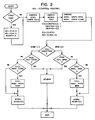
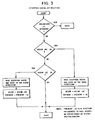
- FIGS 2 and 3 are computer program flow diagrams.
- stepper motor 10 is arranged by source basin 12 holding a supply 13 of liquid.
- Stepper motor 10 also referred to as a stepping motor, has a suitable mechanical transmission 11 to move plug 14 in the line of arrow A into and out of a corresponding valve coat for causing liquid to flow into delivery tube 16 at rates varying with the amount of displacement of plug 14 out of contact with the valve seat.
- a suitable transmission is of the type shown in Figure 6 of U.S. Patent No. 2,804,665.
- the stepper motor can, as well, operate an orifice-varying diaphragm. Or it can operate a cam to push against a flexible siphon tube to constrict, or open, the tube for flow variation. Another possibility would be to arrange the stepper motor to vary fuel, or electricity, to a pump bringing liquid to container 18.
- container 18 is a containment in which a constant static head of liquid is required. It may, for instance, be the mold of an electromagnetic caster, or the tundish of a roll caster, where a constant static head is of advantage for obtaining uniform solid product in the continuous casting of molten metal.
- controlled level 20 The level to which liquid in container 18 is controlled is indicated by controlled level 20.
- the liquid is dispensed from container 18 through outlet 22. Alternatively, it may be dispensed to a liquid-solid interface, as in continuous casting of metal.
- Level sensor 24 may be of the type including one or more inductive coils and referred to as an eddy current sensing device. Its output signal changes as a function of the distance between it and the liquid level when the liquid is metal, such as molten aluminum.
- level sensors such as those using radioactive material emitting gamma rays, those sensing heat radiation from hot metal, those relying on electrical resistance changes, etc.
- Analog to digital converter (ADC) 25 outputs to controller 26 digital signals representative of the analog signals from the sensor 24.
- Controller 26 which may, for instance, be a digital microcomputer, emits pulses to move stepper motor 10.
- a stepper motor translator may be interposed between the stepper motor and the controller to assure, for example, that the motor movement is in the correct direction.
- the bus from the controller will typically have several conductors to carry signals determining direction of motor movement and the amount of movement. serial transmission may as well be used.
- a PDD-type control is utilized to control liquid level 20.
- Controller 26 is provided with a setpoint, representative of level 20 in Figure 1.
- the signal from level sensor 24 is compared with the setpoint and the difference noted as the error.
- the error is the distance X out of level 20. Distance X may be positive or negative.
- PDD Proportional-derivative derivative
- Error measurements are made every TD seconds, for instance every 0.1 second, and placed in a stack of three memory locations, X(t) contains the present error, X(t - 1) the error measured 0.1 second ago, and X(t - 2) the error from 0.2 second ago.
- Typical values for C1, C2 and C3 are 0.85, 6.67 and 0.10. Values of C1, C2 and C3 for a given control situation can be determined by methods known to those skilled in the art, one such method being that referred to as "root locus pole placement".
- Figures 2 and 3 are flow diagrams for the computer programs implementing the control equation for Y(t) as given above.
- the next operation involves calculating Y(t) via the control equation.
- Y(t) is computed always as an integer, each increment representing one-tenth of one stepper motor step.
- the end part of this operation includes transferring X(t - 1) into the storage location for X(t - 2) and X(t) into the location for X(t - 1), in preparation for the next pass through the flow chart, 0.1 second (100 msec) later.
- the following operation compares the present valve plug position (PRESENT from Fig. 3) to the plug closed position and the plug open position to compute available steps in the open and close directions. Increments here likewise correspond to one-tenth of one motor step.
- the plug closed position may be stored in the controller as a zero value established at system initialization. One way of doing this is to adjust the linkage between the plug and the motor shaft such that a notch in the shaft is aligned with a magnetic sensor when the plug is closed, i.e. seated in the valve seat. The resulting signal from the magnetic sensor causes the zero value to be stored in the controller.
- the fully open plug position is stored as an appropriately large integer such that further plug opening has little effect toward increasing liquid flow.
- the angular difference in motor shaft position between open and close will typically be less than 360°, an example being 180°.
- the calculated Y(t) is then subjected to analysis, as shown in the remainder of Figure 2, to obtain an updated ACCUM for evaluation in the stepper handler routine in Figure 3.
- the main control routine of Figure 2 is, for example, repeated every 0.1 second, while the routine of Figure 3 repeats every 0.0125 second, for a stepper motor requiring 0.010 second for each step.
- the stepper handler routine of Figure 3 evaluates ACCUM and outputs one motor step whenever the absolute value of ACCUM is greater than 10.
- the present location of the plug relative to its closed position is computed as PRESENT.
- DEADBAND is typically zero, but is provided so that a deadband can be used if desired.
- Tests using the control of the invention for level control in continuous casting of metal show ability to control level to within 0.005 inch of set point reference.
- a further advantage of the invention is that a sensor is not needed for present plug position.
Landscapes
- Physics & Mathematics (AREA)
- General Physics & Mathematics (AREA)
- Engineering & Computer Science (AREA)
- Automation & Control Theory (AREA)
- Flow Control (AREA)
- Control Of Non-Electrical Variables (AREA)
Description
- It is an object of the invention to provide an improved control of liquid level.
- This as well as other objects which will become apparent from the discussion that follows are achieved, according to the present invention, by providing an apparatus for controlling liquid level, including containment means for containing and dispensing liquid, flow varying means operable for varying flow of liquid into the containment means, stepper motor means for operating the flow varying means, sensor means for sensing level of liquid in the containment means, and PDD controller means connected between the sensor means and the stepper motor means for controlling liquid level. A corresponding method is likewise provided.
- US-A-2 804 665 discloses continuous casting of metal, in which the level of molten metal is controlled by sensing the level of molten metal in a mold, comparing the sensed level with desired conditions by means of a control mechanism, and varying the tilting rate of a molten metal supply vessel through regulation by the control mechanism.
- DF-A-2 941 544 concerns regulating fluid level in a container, wherein rate of change detection circuits monitor signals at various points in a control system for detecting sudden changes in a critiical signal indicative of a fault.
- Figure 1 is a schematic representation of the apparatus of the invention.
- Figures 2 and 3 are computer program flow diagrams.
- With reference to Figure 1,
stepper motor 10 is arranged bysource basin 12 holding asupply 13 of liquid.Stepper motor 10, also referred to as a stepping motor, has a suitable mechanical transmission 11 to moveplug 14 in the line of arrow A into and out of a corresponding valve coat for causing liquid to flow intodelivery tube 16 at rates varying with the amount of displacement ofplug 14 out of contact with the valve seat. - A suitable transmission is of the type shown in Figure 6 of U.S. Patent No. 2,804,665.
- It will be recognized, for course, that other means of varying flow are possible. The stepper motor can, as well, operate an orifice-varying diaphragm. Or it can operate a cam to push against a flexible siphon tube to constrict, or open, the tube for flow variation. Another possibility would be to arrange the stepper motor to vary fuel, or electricity, to a pump bringing liquid to
container 18. - In a preferred embodiment,
container 18 is a containment in which a constant static head of liquid is required. It may, for instance, be the mold of an electromagnetic caster, or the tundish of a roll caster, where a constant static head is of advantage for obtaining uniform solid product in the continuous casting of molten metal. - The level to which liquid in
container 18 is controlled is indicated by controlledlevel 20. The liquid is dispensed fromcontainer 18 throughoutlet 22. Alternatively, it may be dispensed to a liquid-solid interface, as in continuous casting of metal. -
Level sensor 24 may be of the type including one or more inductive coils and referred to as an eddy current sensing device. Its output signal changes as a function of the distance between it and the liquid level when the liquid is metal, such as molten aluminum. - Other level sensors are possible, such as those using radioactive material emitting gamma rays, those sensing heat radiation from hot metal, those relying on electrical resistance changes, etc.
- Analog to digital converter (ADC) 25 outputs to controller 26 digital signals representative of the analog signals from the
sensor 24. -
Controller 26, which may, for instance, be a digital microcomputer, emits pulses to movestepper motor 10. A stepper motor translator may be interposed between the stepper motor and the controller to assure, for example, that the motor movement is in the correct direction. The bus from the controller will typically have several conductors to carry signals determining direction of motor movement and the amount of movement. serial transmission may as well be used. - According to the invention, a PDD-type control is utilized to control
liquid level 20.Controller 26 is provided with a setpoint, representative oflevel 20 in Figure 1. The signal fromlevel sensor 24 is compared with the setpoint and the difference noted as the error. In Figure 1, the error is the distance X out oflevel 20. Distance X may be positive or negative. - The term "PDD" is short for "proportional-derivative derivative". This type of control is characterized by adjustment of the controlling parameter, in this case position Y of the
plug 14, in direct proportion to the error X, as well as in dependence on the first time derivative of X and on the second time derivative. - The equation utilized in the computer program in the microcomputer embodiment of the controller is

where


In these equations, "*" signifies multiplication, "/" division, and "**" means "raised to the power of".
The symbols are defined as follows: - "t" denotes the instantaneous value of time in seconds with zero corresponding to the start of algorithm execution.
- "Y(t)" denotes the instantaneous value of the controller output at time "t". That is, Y(5) corresponds to the value of the controller output 5 seconds after system startup. In the level control application, the controller output is the command signal sent to the metal flow control device.
- Likewise, "X(t)" denotes the instantaneous value of the controller input at time "t", In the level control application, the controller input is the difference between the desired level and the measured value provided by a suitable sensing device.
- "C1" through "C3" represent constant coefficients in the linear control law equation provided. Values for these constants are determined by analyzing the dynamics of the uncompensated system with respect to the desired closed-loop performance. Suitable analysis techniques include root locus and frequency response methods well known to control engineers.
- "TD" denotes the sample rate of the digital system in seconds per sample. This parameter indicates the rate at which the given equation is executed, a typical value being 0.100 seconds per sample. In this case, the equation would be used to produce a new value of Y(t) every 0.100 seconds. To do so, it would require knowledge of X(t), X(t-TD) and X(t-2*TD). Note that X(t-TD) represents the instantaneous value of the controller input at time (t-TD). This corresponds to the value or X(t), delayed by TD seconds. Likewise, X(t-2*TD) represents the value of X(t), delayed by 2*TD seconds. Thus, Y(t) is formed from the current value of the input [X(t)], the value of the input during the previous sample period [X(t-TD)] and the value of the input two sample periods into the past [X(t-2*TD)].
- Error measurements are made every TD seconds, for instance every 0.1 second, and placed in a stack of three memory locations, X(t) contains the present error, X(t - 1) the error measured 0.1 second ago, and X(t - 2) the error from 0.2 second ago.
- Typical values for C1, C2 and C3 are 0.85, 6.67 and 0.10. Values of C1, C2 and C3 for a given control situation can be determined by methods known to those skilled in the art, one such method being that referred to as "root locus pole placement".
- The above equation utilized in the computer program was derived by us on the basis of the following considerations:
Having decided that we wanted PDD-type control, we set

where "s" is the Laplace operator. This leads to
Expressing this in the Z domain,

for

Expanding the term (1 - Z**(-1))² and consolidating gives

And, this leads to the above formula for Y(t) for use in the microcomputer program. - Figures 2 and 3 are flow diagrams for the computer programs implementing the control equation for Y(t) as given above.
- In the "compute level error" operation, input from the level sensor is substracted from the set point to determine error X(t) in inches, X being distance as shown in Figure 1. This is the X value at the present time "t".
- The next operation involves calculating Y(t) via the control equation. Y(t) is computed always as an integer, each increment representing one-tenth of one stepper motor step. The end part of this operation includes transferring X(t - 1) into the storage location for X(t - 2) and X(t) into the location for X(t - 1), in preparation for the next pass through the flow chart, 0.1 second (100 msec) later.
- The following operation compares the present valve plug position (PRESENT from Fig. 3) to the plug closed position and the plug open position to compute available steps in the open and close directions. Increments here likewise correspond to one-tenth of one motor step. The plug closed position may be stored in the controller as a zero value established at system initialization. One way of doing this is to adjust the linkage between the plug and the motor shaft such that a notch in the shaft is aligned with a magnetic sensor when the plug is closed, i.e. seated in the valve seat. The resulting signal from the magnetic sensor causes the zero value to be stored in the controller. The fully open plug position is stored as an appropriately large integer such that further plug opening has little effect toward increasing liquid flow. The angular difference in motor shaft position between open and close will typically be less than 360°, an example being 180°.
- The calculated Y(t) is then subjected to analysis, as shown in the remainder of Figure 2, to obtain an updated ACCUM for evaluation in the stepper handler routine in Figure 3.
- The main control routine of Figure 2 is, for example, repeated every 0.1 second, while the routine of Figure 3 repeats every 0.0125 second, for a stepper motor requiring 0.010 second for each step.
- The stepper handler routine of Figure 3 evaluates ACCUM and outputs one motor step whenever the absolute value of ACCUM is greater than 10. The present location of the plug relative to its closed position is computed as PRESENT. DEADBAND is typically zero, but is provided so that a deadband can be used if desired.
- Tests using the control of the invention for level control in continuous casting of metal show ability to control level to within 0.005 inch of set point reference.
- Accumulation of fractional stepper motor steps leads to a tighter, more accurate control than would be the case if, for instance, values of Y(t) less than one step were discarded.
- A further advantage of the invention is that a sensor is not needed for present plug position.
Claims (4)
- An apparatus for controlling liquid level (20), comprising containment means (18) for containing and dispensing liquid, flow varying means (11,14) operable for varying flow of liquid into the containment means, and sensor means (24) for sensing level of liquid in the containment means, characterized by stepper motor means (10) for operating the flow varying means, and PDD controller means (26) connected between the sensor means (24) and stepper motor means (10) for controlling liquid level.
- An apparatus as claimed in claim 1, the PDD controller means (26) functioning according to

where



and wherein
"t" denotes the instantaneous value of time in seconds with zero corresponding to the start of algorithm execution;
"Y(t)" denotes the instantaneous value of the controller output at time "t";
"X(t)" denotes the instantaneous value of the controller input at time "t";
"C1" through "C3" represent constant coefficients;
"TD" denotes the sample rate of the digital system in seconds per sample;
"*" signifies multiplication; and
"**" means "raised to the power of". - An apparatus as claimed in claim 2, wherein fractional motor steps are accumulated and steps are executed upon attainment of a whole step.
- A method for controlling level (20) of a liquid being dispensed from containment means (18), said liquid being supplied to said containment means through flow varying means (11,14) operable for varying the flow of liquid into the containment means, comprising sensing the liquid level (20) and comparing the sensed level to a setpoint for determining error, characterized by varying flow of replenishment liquid into the containment means (18) by a stepper motor (10), the steps of stepper motor movement being the sum of a term proportional to the error itself, a term proportional to the first time derivative of the error and a term proportional to the second time derivative of the error.
Applications Claiming Priority (2)
| Application Number | Priority Date | Filing Date | Title |
|---|---|---|---|
| US06/684,619 US4660586A (en) | 1984-12-21 | 1984-12-21 | Liquid level control |
| US684619 | 1991-04-12 |
Publications (3)
| Publication Number | Publication Date |
|---|---|
| EP0186116A2 EP0186116A2 (en) | 1986-07-02 |
| EP0186116A3 EP0186116A3 (en) | 1988-01-20 |
| EP0186116B1 true EP0186116B1 (en) | 1994-06-15 |
Family
ID=24748820
Family Applications (1)
| Application Number | Title | Priority Date | Filing Date |
|---|---|---|---|
| EP85116157A Expired - Lifetime EP0186116B1 (en) | 1984-12-21 | 1985-12-18 | Liquid level control |
Country Status (6)
| Country | Link |
|---|---|
| US (1) | US4660586A (en) |
| EP (1) | EP0186116B1 (en) |
| AU (1) | AU570165B2 (en) |
| CA (1) | CA1238963A (en) |
| DE (1) | DE3587854T2 (en) |
| NO (1) | NO175956C (en) |
Families Citing this family (16)
| Publication number | Priority date | Publication date | Assignee | Title |
|---|---|---|---|---|
| US4827762A (en) * | 1985-06-26 | 1989-05-09 | Hasselmann Detlev E M | System and method for automatically monitoring liquid volume changes in storage tanks |
| GB2186712B (en) * | 1986-02-14 | 1989-11-01 | British Nuclear Fuels Plc | Interface control apparatus |
| JPH0635921Y2 (en) * | 1987-11-20 | 1994-09-21 | 四国化工機株式会社 | Level controller for filling liquid level in packaging tube |
| US5000220A (en) * | 1988-10-14 | 1991-03-19 | Allied-Signal Inc. | Metering valve with follow-up servo |
| FR2677284B1 (en) * | 1991-06-07 | 1993-08-27 | Pechiney Aluminium | PROCESS AND APPARATUS FOR AUTOMATIC CASTING OF SEMI-PRODUCTS. |
| ZA948879B (en) * | 1993-11-13 | 1996-02-05 | Mintek | A process for controlling a series of flotation cells |
| WO1997048477A1 (en) * | 1996-06-21 | 1997-12-24 | Jordan Holding Company | Return circuit for vapor recovery system |
| US5954078A (en) * | 1997-03-20 | 1999-09-21 | Taiwan Semiconductor Manufacturing Company, Ltd. | Method and apparatus for handling liquid chemical waste |
| US6026837A (en) * | 1997-05-14 | 2000-02-22 | Taiwan Semiconductor Manufacturing Company, Ltd. | Automated chemical drain system |
| US6453939B1 (en) | 1997-07-01 | 2002-09-24 | Baker Hughes Incorporated | Flotation cell fluid level control apparatus |
| US5985028A (en) | 1997-09-12 | 1999-11-16 | Henkel Corporation | Coating apparatus |
| US6279493B1 (en) | 1998-10-19 | 2001-08-28 | Eco/Technologies, Llc | Co-combustion of waste sludge in municipal waste combustors and other furnaces |
| US6553924B2 (en) | 1998-10-19 | 2003-04-29 | Eco/Technologies, Llc | Co-combustion of waste sludge in municipal waste combustors and other furnaces |
| KR100393289B1 (en) * | 2001-06-26 | 2003-07-31 | 주식회사 실리콘 테크 | Photoresist output monitoring system |
| US7531350B2 (en) * | 2005-04-20 | 2009-05-12 | Agricultural Research Institute | Bioreactor for growing fungus, plant cell, tissue, organ, hairy roots and plantlet |
| DE102009051351B4 (en) * | 2009-10-30 | 2014-07-10 | Siemens Aktiengesellschaft | Rail vehicle with fill level monitoring of a wastewater tank |
Citations (1)
| Publication number | Priority date | Publication date | Assignee | Title |
|---|---|---|---|---|
| DE2941544A1 (en) * | 1978-10-23 | 1980-04-24 | Gen Electric | METHOD FOR MAINTAINING THE FLUID LEVEL IN A FLUID FILLED CONTAINER |
Family Cites Families (16)
| Publication number | Priority date | Publication date | Assignee | Title |
|---|---|---|---|---|
| US2612180A (en) * | 1950-03-08 | 1952-09-30 | Lathrop Paulson Co | Weigh can dumping control |
| US2804665A (en) * | 1955-09-22 | 1957-09-03 | Babcock & Wilcox Co | Method of and apparatus for continuously casting metal |
| US2997205A (en) * | 1958-06-04 | 1961-08-22 | United States Steel Corp | Method and apparatus for controlling discharge of materials |
| US3268117A (en) * | 1965-04-09 | 1966-08-23 | Beckman Instruments Inc | Dispensing head |
| US3329313A (en) * | 1965-09-29 | 1967-07-04 | Howe Richardson Scale Co | Constant weight feeding apparatus |
| US3373910A (en) * | 1965-10-20 | 1968-03-19 | Crawford B. Murton | Stopper rod with temperature responsive cooling means |
| FR1473044A (en) * | 1965-12-14 | 1967-03-17 | Siderurgie Fse Inst Rech | Method and device for obtaining a constant flow of liquid metal |
| US3671142A (en) * | 1970-06-22 | 1972-06-20 | Lumenite Electronic Co | Liquid level control |
| US3730695A (en) * | 1971-03-23 | 1973-05-01 | Owens Corning Fiberglass Corp | Level control means for glass fiber making process |
| FR2337904A1 (en) * | 1976-01-09 | 1977-08-05 | Rossi Ernest Claude | Separator of upper liquid layer in reservoir - has trough lowered vertically into liquid under programmed motor control |
| US4265262A (en) * | 1979-03-19 | 1981-05-05 | William Hotine | Fluent material level control system |
| DE2940710C2 (en) * | 1979-10-08 | 1983-06-09 | Hartmann & Braun Ag, 6000 Frankfurt | Electrical control device with PIDD 2 behavior |
| US4244385A (en) * | 1979-12-12 | 1981-01-13 | William Hotine | Fluent material level control system |
| FR2514497A1 (en) * | 1981-10-08 | 1983-04-15 | Jaeger | HOT WIRE LEVEL DIGITAL LEVEL DETECTION DEVICE |
| US4416153A (en) * | 1982-03-15 | 1983-11-22 | Innovative Medical Systems, Corp. | Method of compensating a thermistor |
| US4481453A (en) * | 1982-07-23 | 1984-11-06 | Motornetics Corporation | Torque loop control system and method |
-
1984
- 1984-12-21 US US06/684,619 patent/US4660586A/en not_active Expired - Fee Related
-
1985
- 1985-07-03 AU AU44532/85A patent/AU570165B2/en not_active Ceased
- 1985-07-04 CA CA000486305A patent/CA1238963A/en not_active Expired
- 1985-12-18 DE DE3587854T patent/DE3587854T2/en not_active Expired - Fee Related
- 1985-12-18 EP EP85116157A patent/EP0186116B1/en not_active Expired - Lifetime
- 1985-12-20 NO NO855206A patent/NO175956C/en unknown
Patent Citations (1)
| Publication number | Priority date | Publication date | Assignee | Title |
|---|---|---|---|---|
| DE2941544A1 (en) * | 1978-10-23 | 1980-04-24 | Gen Electric | METHOD FOR MAINTAINING THE FLUID LEVEL IN A FLUID FILLED CONTAINER |
Also Published As
| Publication number | Publication date |
|---|---|
| CA1238963A (en) | 1988-07-05 |
| US4660586A (en) | 1987-04-28 |
| EP0186116A2 (en) | 1986-07-02 |
| EP0186116A3 (en) | 1988-01-20 |
| AU4453285A (en) | 1986-06-26 |
| DE3587854D1 (en) | 1994-07-28 |
| NO175956B (en) | 1994-09-26 |
| NO175956C (en) | 1995-01-04 |
| AU570165B2 (en) | 1988-03-03 |
| DE3587854T2 (en) | 1995-01-12 |
| NO855206L (en) | 1986-06-23 |
Similar Documents
| Publication | Publication Date | Title |
|---|---|---|
| US4660586A (en) | Liquid level control | |
| KR100684539B1 (en) | Method of controlling gas flow rate in digital mass flow controller, digital mass flow controller, system and method for generating digital enhanced flow rate signal | |
| EP0417782B1 (en) | Adaptive process control system, especially for control of temperature of flowing fluids | |
| JP3296568B2 (en) | Compensation for overfilling of batch delivery systems | |
| US4303797A (en) | Method and apparatus for controlling electrode drive speed in a consumable electrode furnace | |
| US4766966A (en) | Apparatus and method of controlling rate of feeding product to weigher | |
| US4738295A (en) | Method and apparatus for evaporating a fluid in a rotating vacuum evaporation system | |
| EP0076840A4 (en) | Fluid flow control system. | |
| CA1322890C (en) | Flow rate control system | |
| US4197273A (en) | Apparatus for controlling the directional solidification of a liquid-solid system | |
| CA1318224C (en) | System for controlling apparatus for growing tubular crystalline bodies | |
| EP0572245B1 (en) | Method and apparatus for analyzing process characteristics | |
| Winkler et al. | A review of the automation of the Czochralski crystal growth process | |
| US4019563A (en) | Method and apparatus for controlling the batching of a melt for pressure tapping furnace | |
| CA2370154C (en) | Method of determining the salt content of liquids and device for practicing the method | |
| EP0510595A2 (en) | Method measurement of polymer molecular weight | |
| US5844143A (en) | Electromagnetic flowmeter | |
| RU2167449C2 (en) | Method for automatic temperature control in apparatus with heating jacket | |
| RU2115154C1 (en) | Method of temperature control in electric furnace | |
| JPS6215435B2 (en) | ||
| SU785651A1 (en) | Liquid level gauge | |
| JPH03167611A (en) | Control device for fluid in a container | |
| JPH05228061A (en) | Electric pot | |
| JPH06343282A (en) | Vector controller for induction motor | |
| KR100978267B1 (en) | PID Auto-Tuning Method Using Response Curve Method |
Legal Events
| Date | Code | Title | Description |
|---|---|---|---|
| PUAI | Public reference made under article 153(3) epc to a published international application that has entered the european phase |
Free format text: ORIGINAL CODE: 0009012 |
|
| AK | Designated contracting states |
Kind code of ref document: A2 Designated state(s): CH DE FR GB LI |
|
| PUAL | Search report despatched |
Free format text: ORIGINAL CODE: 0009013 |
|
| AK | Designated contracting states |
Kind code of ref document: A3 Designated state(s): CH DE FR GB LI |
|
| 17P | Request for examination filed |
Effective date: 19880704 |
|
| 17Q | First examination report despatched |
Effective date: 19900525 |
|
| GRAA | (expected) grant |
Free format text: ORIGINAL CODE: 0009210 |
|
| AK | Designated contracting states |
Kind code of ref document: B1 Designated state(s): CH DE FR GB LI |
|
| REF | Corresponds to: |
Ref document number: 3587854 Country of ref document: DE Date of ref document: 19940728 |
|
| ET | Fr: translation filed | ||
| PLBE | No opposition filed within time limit |
Free format text: ORIGINAL CODE: 0009261 |
|
| STAA | Information on the status of an ep patent application or granted ep patent |
Free format text: STATUS: NO OPPOSITION FILED WITHIN TIME LIMIT |
|
| 26N | No opposition filed | ||
| PGFP | Annual fee paid to national office [announced via postgrant information from national office to epo] |
Ref country code: CH Payment date: 19951113 Year of fee payment: 11 |
|
| PGFP | Annual fee paid to national office [announced via postgrant information from national office to epo] |
Ref country code: FR Payment date: 19951121 Year of fee payment: 11 |
|
| PGFP | Annual fee paid to national office [announced via postgrant information from national office to epo] |
Ref country code: GB Payment date: 19951123 Year of fee payment: 11 |
|
| PGFP | Annual fee paid to national office [announced via postgrant information from national office to epo] |
Ref country code: DE Payment date: 19951129 Year of fee payment: 11 |
|
| PG25 | Lapsed in a contracting state [announced via postgrant information from national office to epo] |
Ref country code: GB Effective date: 19961218 |
|
| PG25 | Lapsed in a contracting state [announced via postgrant information from national office to epo] |
Ref country code: LI Effective date: 19961231 Ref country code: CH Effective date: 19961231 |
|
| GBPC | Gb: european patent ceased through non-payment of renewal fee |
Effective date: 19961218 |
|
| REG | Reference to a national code |
Ref country code: CH Ref legal event code: PL |
|
| PG25 | Lapsed in a contracting state [announced via postgrant information from national office to epo] |
Ref country code: FR Effective date: 19970829 |
|
| PG25 | Lapsed in a contracting state [announced via postgrant information from national office to epo] |
Ref country code: DE Effective date: 19970902 |
|
| REG | Reference to a national code |
Ref country code: FR Ref legal event code: ST |