EP0185839B1 - Sound-absorbing body made of foam material - Google Patents
Sound-absorbing body made of foam material Download PDFInfo
- Publication number
- EP0185839B1 EP0185839B1 EP85109039A EP85109039A EP0185839B1 EP 0185839 B1 EP0185839 B1 EP 0185839B1 EP 85109039 A EP85109039 A EP 85109039A EP 85109039 A EP85109039 A EP 85109039A EP 0185839 B1 EP0185839 B1 EP 0185839B1
- Authority
- EP
- European Patent Office
- Prior art keywords
- layer
- foam
- openings
- tool
- hollow body
- Prior art date
- Legal status (The legal status is an assumption and is not a legal conclusion. Google has not performed a legal analysis and makes no representation as to the accuracy of the status listed.)
- Expired - Lifetime
Links
Images

Classifications
-
- B—PERFORMING OPERATIONS; TRANSPORTING
- B32—LAYERED PRODUCTS
- B32B—LAYERED PRODUCTS, i.e. PRODUCTS BUILT-UP OF STRATA OF FLAT OR NON-FLAT, e.g. CELLULAR OR HONEYCOMB, FORM
- B32B5/00—Layered products characterised by the non- homogeneity or physical structure, i.e. comprising a fibrous, filamentary, particulate or foam layer; Layered products characterised by having a layer differing constitutionally or physically in different parts
- B32B5/18—Layered products characterised by the non- homogeneity or physical structure, i.e. comprising a fibrous, filamentary, particulate or foam layer; Layered products characterised by having a layer differing constitutionally or physically in different parts characterised by features of a layer of foamed material
-
- B—PERFORMING OPERATIONS; TRANSPORTING
- B32—LAYERED PRODUCTS
- B32B—LAYERED PRODUCTS, i.e. PRODUCTS BUILT-UP OF STRATA OF FLAT OR NON-FLAT, e.g. CELLULAR OR HONEYCOMB, FORM
- B32B3/00—Layered products comprising a layer with external or internal discontinuities or unevennesses, or a layer of non-planar form; Layered products having particular features of form
- B32B3/26—Layered products comprising a layer with external or internal discontinuities or unevennesses, or a layer of non-planar form; Layered products having particular features of form characterised by a particular shape of the outline of the cross-section of a continuous layer; characterised by a layer with cavities or internal voids ; characterised by an apertured layer
- B32B3/266—Layered products comprising a layer with external or internal discontinuities or unevennesses, or a layer of non-planar form; Layered products having particular features of form characterised by a particular shape of the outline of the cross-section of a continuous layer; characterised by a layer with cavities or internal voids ; characterised by an apertured layer characterised by an apertured layer, the apertures going through the whole thickness of the layer, e.g. expanded metal, perforated layer, slit layer regular cells B32B3/12
-
- G—PHYSICS
- G10—MUSICAL INSTRUMENTS; ACOUSTICS
- G10K—SOUND-PRODUCING DEVICES; METHODS OR DEVICES FOR PROTECTING AGAINST, OR FOR DAMPING, NOISE OR OTHER ACOUSTIC WAVES IN GENERAL; ACOUSTICS NOT OTHERWISE PROVIDED FOR
- G10K11/00—Methods or devices for transmitting, conducting or directing sound in general; Methods or devices for protecting against, or for damping, noise or other acoustic waves in general
- G10K11/16—Methods or devices for protecting against, or for damping, noise or other acoustic waves in general
- G10K11/162—Selection of materials
- G10K11/168—Plural layers of different materials, e.g. sandwiches
-
- B—PERFORMING OPERATIONS; TRANSPORTING
- B32—LAYERED PRODUCTS
- B32B—LAYERED PRODUCTS, i.e. PRODUCTS BUILT-UP OF STRATA OF FLAT OR NON-FLAT, e.g. CELLULAR OR HONEYCOMB, FORM
- B32B2307/00—Properties of the layers or laminate
- B32B2307/10—Properties of the layers or laminate having particular acoustical properties
-
- B—PERFORMING OPERATIONS; TRANSPORTING
- B32—LAYERED PRODUCTS
- B32B—LAYERED PRODUCTS, i.e. PRODUCTS BUILT-UP OF STRATA OF FLAT OR NON-FLAT, e.g. CELLULAR OR HONEYCOMB, FORM
- B32B2307/00—Properties of the layers or laminate
- B32B2307/70—Other properties
- B32B2307/724—Permeability to gases, adsorption
Definitions
- the invention relates to a foam sound absorption body with surface connection between an air-permeable foam layer and a stabilization layer equipped with openings.
- the object of the invention is to provide, while maintaining the principle of the flow-optimized absorber, a foam sound absorption body which, even with an extreme relief structure, has a homogeneous flow resistance value, with high strength and simple manufacture.
- the stabilizing layer is a broad side wall of a relining hollow body pressed against the foam layer with thermal deformation, the openings of which consist of holes pierced from the foam side.
- a generic flow-optimized sound absorption hollow body is created, which brings an even further improved efficiency with the lowest material expenditure and high shape adaptability.
- the use of, for example, thermoplastic compact material to produce the lattice layer also proves to be extremely favorable in terms of production technology.
- the holes made from the foam side can even be individually provided in their accumulation or density. This takes different noise source zones even better into account.
- the perforated collars which may arise during the perforation project into the cavity of the hollow body; they do not require post-processing.
- the outside, funnel-like hole widenings even represent particularly effective collectors.
- the holes can be taken into account in a particularly economical manner when forming the relining hollow body, although this could also be done in a subsequent or separate operation.
- the production can then be carried out on conventional tools.
- the blow molding process is particularly suitable here.
- the foam layer is placed in the mold.
- a hose is extruded.
- the blow mandrel enters the tube.
- the tool closes.
- the tube is now inflated. It adopts the tool contour, both with regard to the mold half that forms the broad side wall and with respect to the mold half that has the carrier contour.
- a needle tool moves in from the foam side with the aim of the perforation explained.
- the needle tool moves back.
- the tool opens.
- the finished workpiece falls out.
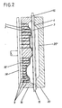
- the procedure is similar, with the difference that instead of a tubular starting body, two layers are introduced into the tool, one of which forms the stabilizing layer and the other the support layer.
- the shaping may be brought about by central overpressure or by an external vacuum.
- An economical tool for producing such a foam sound absorption body is advantageously designed in such a way that the wall of one mold half is provided with openings, in which piercing needles are displaceably guided, which, beyond the inner contour surface of the mold half, extend into a spaced position extend to the inner contour surface of the other mold half so that the backing layer is not perforated.
- the foam sound absorption body shown in FIGS. 3 and 4 is realized as a hollow body K. Its cavity can still be subdivided.
- the hollow body K is composed of an external foam layer 1 made of open-cell, optionally structure-compressed, air-permeable foam plastic. The latter is on the noise source side.
- a sound-transparent stabilization layer 2 extends behind it.
- the cavity 3 follows, which is delimited by a so-called carrier layer 4. The latter can be thick-walled than the layer 2.
- Stabilizing layer 2 and carrier layer 4 consist of thermoplastic compact material. Stabilization layer 2 and carrier layer 4 are connected at the edges. For example, to achieve chambering, the central area is also the Stabilization layer 2 still connected to the corresponding area of the carrier layer.
- the connection points formed by sealing zones have the reference symbol 5.
- the carrier layer 4 has a cross-sectional shape that is essentially only trough-shaped, that is to say has a flat bottom.
- the distance to the reverberant wall e.g. bonnet of a motor vehicle
- Such indentations can be cup-shaped or kidney-shaped.
- a step pyramid is also conceivable.
- One of these distances, which is to be selected differently depending on the frequency, is designated by x.
- Application WO 84/02998 contains a detailed discussion.
- the stabilization layer 2 is pressed against the foam layer 1 with thermal deformation.
- the latter leads to a firm connection of the boundary layer 6 of the foam layer 1 facing away from the noise source to the corresponding surface of the stabilization layer 2 forming the broad side wall of the relining hollow body K.
- the slightly softened plastic penetrates somewhat into the pores 7 of the foam layer 1 and finds one there high-grade, but not very deep anchoring, so that the majority of foam retains its structure, ie open pores 7.
- the nonetheless well-preserved composite is made more symbolically recognizable by hatching in Fig. 4.
- the stabilization layer 2 made of thermoplastic compact material is provided with holes 8 which are pierced from the foam layer side.
- the perforation process results from FIG. 2.
- the collar bears the reference number 10.
- a funnel 11 is formed on the outside, both in the foam layer 1 and in the stabilization layer 2.
- the needle diameter is approximately 1 mm.
- the perforated collar 11 does not need to be removed, since it migrates into a zone which is hidden from view, specifically into the cavity 3.
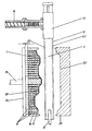
- blow molding process shown in the drawing in FIG. 1 or the hot forming process shown in FIG. 2 are suitable as production processes. While in the latter method the one broad side wall forming the stabilization layer 2 and the carrier layer 4 as another broad side wall consist of separate thermoplastic plastic plates, in the method according to FIG. 1 both walls are formed by one and the same basic body, namely from a thermoplastic hose 12.
- a thermoplastic hose 12 One can Warm pre-made hoses for the blowing process; as a rule, however, blow molding is directly combined with tube production.
- the hot hose emerging from the storage head 13 of the extruder 14 moves into the open tool W.
- the latter corresponds in principle to the insertion of the plates according to FIG. 2.
- a blow mandrel 15 moves into the hose or between the plates. The tool closes.
- the hose or the bpsw. even continuously fed plates are separated.
- Inflation now follows, the hollow body which forms taking on the exact contour of the tool.
- a cooling phase now follows. The holes are pierced during this cooling phase.
- the wall of the mold half 16 forming the stabilization layer 2 has openings 17. The latter extend across the plane E-E of the product.
- the piercing needles 9 arranged displaceably therein extend in these openings 17.
- the latter start from a common base plate 18 which is controlled or moved by a central rod 19.
- the displacement stroke y of the ram is adjusted so that only the stabilization layer 2 is perforated.
- the piercing needles 9 therefore only protrude beyond the inner contour 16 'of the mold half 16 up to a distance from the inner contour surface 20' of the other mold half 20.
- the tool W continues to cool down.
- the needle tool moves back.
- the tool opens.
- the finished component falls out.
- a force pressing the hose wall or the plates from the inside against the respective mold halves there is of course also the possibility of ending the mouths of a vacuum pump on the inner surfaces 16 ', 20', so that the contour-accurate impressions of the visible surfaces of the product are thereby produced .
Abstract
Description
Die Erfindung bezieht sich auf einen Schaumstoff-Schallabsorptionskörper mit Flächenverbindung zwischen einer luftdurchlässigen Schaumstoffschicht und einer mit Durchbrechnungen ausgestatteten Stabilisierungslage.The invention relates to a foam sound absorption body with surface connection between an air-permeable foam layer and a stabilization layer equipped with openings.
Es ist bekannt, offenzelligen Schaumkunststoffe zur Schallabsorption einzusetzen, wozu auf die WO 84/02998 verwiesen wird. Zur Stabilisierung der recht dünnwandigen, luftdurchlässigen Schaumkunststoffschicht wird ein Gitter eingebettet. Die Optimierung der Schallabsorption besteht dabei weiter auch in der Einhaltung einer bestimmten Abstandsstelle zur reflektierenden Wand bzw. Geräuschquelle. Hierbei treten zufolge sorgfältiger Abstimmung auf die Intensität der verschiedenen Geräuschquellen u.U. erhebliche Tiefzieh-Ausformungen auf, welche das eingelegte, die Durchbrechungen bringende Gitter naturgemäß stark belasten können. Es kann zu Rissen in wichtigen Armierungsbereichen kommen, was der Gebrauchsstabilität abträglich ist.It is known to use open-cell foam plastics for sound absorption, for which reference is made to WO 84/02998. A grid is embedded to stabilize the rather thin-walled, air-permeable foam plastic layer. The optimization of sound absorption also consists in maintaining a certain distance from the reflecting wall or noise source. Here, according to careful adjustment to the intensity of the various sources of noise, Significant deep-drawn shapes, which can of course put a heavy load on the inserted grid that brings the openings. There may be cracks in important reinforcement areas, which is detrimental to the stability in use.
Aufgabe der Erfindung ist es, unter Beibehaltung des Prinzips des strömungsoptimierten Absorbers einen Schaumstoff-Schallabsorptionskörper zu schaffen, der selbst bei extremer Reliefstruktur einen homogenen Strömungswiderstandswert aufweist, dies bei trotzdem hoher Festigkeit und einfacher Herstellung.The object of the invention is to provide, while maintaining the principle of the flow-optimized absorber, a foam sound absorption body which, even with an extreme relief structure, has a homogeneous flow resistance value, with high strength and simple manufacture.
Gelöst ist diese Aufgabe gemäß der Erfindung dadurch, daß die Stabilisierungslage eine unter Wärmeverformung gegen die Schaumstoffschicht gedrückte Breitseitenwand eines Unterfütterungs-Hohlkörpers ist, dessen Durchbrechungen aus von der Schaumstoffseite her gestochenen Löchern bestehen.This object is achieved according to the invention in that the stabilizing layer is a broad side wall of a relining hollow body pressed against the foam layer with thermal deformation, the openings of which consist of holes pierced from the foam side.
Zufolge solcher Ausgestaltung ist ein gattungsgemäßer strömungsoptimierter Schallabsorptions-Hohlkörper geschaffen, der bei geringstem Materialaufwand und hoher Form-Anpassungsfähigkeit einen noch weiter verbesserten Wirkungsgrad bringt. Der Einsatz bspw. thermoplastischen Kompaktmaterials zur Erzeugung der Gitterschicht erweist sich auch als fertigungstechnisch äußerst günstig. Die von der Schaumstoffseite her gestochenen Löcher lassen sich in ihrer Häufung bzw. Dichte sogar individuell vorsehen. Hierdurch wird unterschiedlichen Geräuschquellenzonen noch besser Rechnung getragen. Die bei der Lochung möglicherweise entstehenden Lochkragen stehen in den Hohlraum des Hohlkörpers vor; sie bedürfen keiner Nachbearbeitung. Die außenseitigen, trichterartigen Lochverbreiterungen stellen sogar besonders wirksame Kollektoren dar. Die Löcher lassen sich in besonders ökonomischer Weise beim Formen des Unterfütterungs-Hohlkörpers gleich mitberücksichtigen, wenngleich dies auch in einem nachgeschalteten bzw. separaten Arbeitsgang erfolgen könnte. Die Fertigung läßt sich dann auf herkömmlichen Werkzeugen durchführen. Hier bietet sich besonders das Blasformverfahren an. Die Schaumstoffschicht wird in die Form eingelegt. Es erfolgt das Extrudieren eines Schlauches. Der Blasdorn fährt in den Schlauch ein. Das Werkzeug schließt. Der Schlauch wird nun aufgeblasen. Er nimmt die Werkzeugkontur an, und zwar sowohl im Hinblick auf die die Breitseitenwand formende Formhälfte als auch in Bezug auf die die Trägerkontur aufweisende Formhälfte. Nach einer gewissen Abkühlphase fährt von der Schaumstoffseite her ein Nadelwerkzeug ein mit dem Ziel der erläuterten Lochung. Nach weiterem Abkühlen fährt das Nadelwerkzeug zurück. Das Werkzeug öffnet sich. Das fertige Werkstück fällt heraus. Beim normalen Warmumformverfahren wird entsprechend vorgegangen mit dem Unterschied, daß statt eines schlauchförmigen Ausgangskörpers zwei Lagen in das Werkzeug eingeführt werden, von denen die eine die Stabilisierungslage und die andere die Trägerschicht bildet. Das Ausformen mag dabei durch zentralen Überdruck oder durch außenseitiges Vakuum bewirkt werden. Ein wirtschaftliches Werkzeug zur Herstellung eines solchen Schaumstoff-Schallabsorptionskörpers ist in vorteilhafter Weise dahingehend gestaltet, daß die Wand der einen Formhälfte mit Durchbrechungen ausgestattet ist, in welchen Durchstechnadeln verschieblich geführt sind, welche, über die Innen-Konturenfläche der Formhälfte hinaustretend, bis in eine Abstandsstellung zur InnenKonturfläche der anderen Formhälfte reichen, so daß die Trägerschicht nicht mitgelocht wird.As a result of such an embodiment, a generic flow-optimized sound absorption hollow body is created, which brings an even further improved efficiency with the lowest material expenditure and high shape adaptability. The use of, for example, thermoplastic compact material to produce the lattice layer also proves to be extremely favorable in terms of production technology. The holes made from the foam side can even be individually provided in their accumulation or density. This takes different noise source zones even better into account. The perforated collars which may arise during the perforation project into the cavity of the hollow body; they do not require post-processing. The outside, funnel-like hole widenings even represent particularly effective collectors. The holes can be taken into account in a particularly economical manner when forming the relining hollow body, although this could also be done in a subsequent or separate operation. The production can then be carried out on conventional tools. The blow molding process is particularly suitable here. The foam layer is placed in the mold. A hose is extruded. The blow mandrel enters the tube. The tool closes. The tube is now inflated. It adopts the tool contour, both with regard to the mold half that forms the broad side wall and with respect to the mold half that has the carrier contour. After a certain cooling phase, a needle tool moves in from the foam side with the aim of the perforation explained. After further cooling, the needle tool moves back. The tool opens. The finished workpiece falls out. In the normal hot forming process, the procedure is similar, with the difference that instead of a tubular starting body, two layers are introduced into the tool, one of which forms the stabilizing layer and the other the support layer. The shaping may be brought about by central overpressure or by an external vacuum. An economical tool for producing such a foam sound absorption body is advantageously designed in such a way that the wall of one mold half is provided with openings, in which piercing needles are displaceably guided, which, beyond the inner contour surface of the mold half, extend into a spaced position extend to the inner contour surface of the other mold half so that the backing layer is not perforated.
Der Gegenstand der Erfindung einschließlich Werkzeug sind nachstehend anhand eines zeichnerisch veranschaulichten Ausführungsbeispieles näher erläutert. Es zeigt
- Fig. 1 die Herstellung des Schaumstoff-Schallabsorptionskörpers unter Anwendung des Blasformverfahrens, und zwar bei noch nicht geschlossenem Werkzeug,
- Fig. 2 die Herstellung des Schallabsorptionskörpers unter Anwendung des Warmumformverfahrens,
- Fig. 3 das nach diesem Verfahren hergestellte Produkt im Längsschnitt und
- Fig. 4 eine Herausvergrößerung einer Lochungspartie.
- 1 shows the production of the foam sound absorption body using the blow molding process, specifically with the tool not yet closed,
- 2 shows the production of the sound absorption body using the hot forming process,
- Fig. 3 shows the product produced by this method in longitudinal section and
- Fig. 4 is an enlargement of a perforated section.
Der in den Fig. 3 und 4 abgebildete Schaumstoff-Schallabsorptionskörper ist als Hohlkörper K realisiert. Sein Hohlraum kann noch unterteilt, also gekammert sein.The foam sound absorption body shown in FIGS. 3 and 4 is realized as a hollow body K. Its cavity can still be subdivided.
Der Hohlkörper K setzt sich zusammen aus einer außenliegenden Schaumstoffschicht 1 aus offenzelligem, gegebenenfalls strukturverdichtetem, luftdurchlässigem Schaumkunststoff. Letztere liegt geräuschquellenseitig. Dahinter erstreckt sich eine schalltransparente Stabilisierungslage 2. Es folgt der Hohlraum 3, welcher durch eine sogenannte Trägerschicht 4 begrenzt ist. Letztere kann dickwandiger sein als die Lage 2.The hollow body K is composed of an
Stabilisierungslage 2 und Trägerschicht 4 bestehen aus thermoplastischem Kompaktmaterial. Stabilisierungslage 2 und Trägerschicht 4 sind randverbunden. Unter Erzielung einer Kammerung ist bspw. auch der Mittelbereich der Stabilisierungslage 2 noch mit dem korrespondierenden Bereich der Trägerschicht verbunden. Die von Siegelzonen gebildeten Verbindungsstellen tragen das Bezugszeichen 5.Stabilizing
Während die Stabilisierungslage 2, bezogen auf die die randseitige Siegelzone bzw. Fuge schneidende Ebene E-E, beidseitig in eine starke Stufung übergeht, weist die Trägerschicht 4 eine im wesentlichen nur wannenförmige, also einen ebenen Boden tragende Querschnittsform auf. Durch dieses Ausstellen partieller Abschnitte aus der allgemeinen Ebene E-E wird der Abstand zur schallharten Wand (z.B. Motorhaube eines Kraftfahrzeuges) variiert. Solche Einziehungen können topfförmiger oder nierenförmiger Gestalt sein. Auch ist eine Stufenpyramide denkbar. Einer dieser frequenzabhängig unterschiedlich zu wählenden Abstände ist mit x bezeichnet. Eine ausführliche Erörterung enthält die Anmeldung WO 84/ 02998.While the
Die Stabilisierungslage 2 ist unter Wärmeverformung gegen die Schaumstoffschicht 1 gedrückt. Letzteres führt zu einer festen Anbindung der der Geräuschquelle abgewandten Grenzschicht 6 der Schaumstoffschicht 1 an der korrespondierenden Oberfläche der die eine Breitseitenwand des Unterfütterungs-Hohlkörpers K bildenden Stabilisierungslage 2. Der leicht erweichte Kunststoff dringt etwas in die Poren 7 der Schaumstoffschicht 1 ein und findet dort eine hochgradige, allerdings nicht sehr in die Tiefe gehende Verankerung, so daß der überwiegende Schaumstoffanteil seine Struktur behält, d.h. offene Poren 7. Der trotzdem vorliegende, gut haltbare Flächenverbund ist durch Schraffurübertritt in Fig. 4 mehr symbolisch kenntlich gemacht.The
Zur Erzielung des angestrebten Luftdurchlasses ist die aus thermoplastischem Kompaktmaterial bestehende Stabilisierungslage 2 mit von der Schaumstoffschicht-Seite her gestochenen Löchern 8 versehen. Der Perforationsvorgang ergibt sich aus Fig. 2. Die außen von der Breitseitenwand her eintretende Nadel 9 zieht das Material der Stabilisierungslage 2 in Richtung des Hohlraumes 3 etwas kragenartig ein. Der Kragen trägt das Bezugszeichen 10. Vor dem Kragen entsteht außenseitig ein Trichter 11, dies sowohl in der Schaumstoffschicht 1 als auch in der Stabilisierungslage 2. Der Nadeldurchmesser beträgt ca. 1 mm. Der Lochkragen 11 braucht nicht entfernt zu werden, da er in eine der Sicht entzogene Zone hineinwandert, und zwar in den Hohlraum 3.In order to achieve the desired air passage, the
Um bspw. auf einen Strömungswiderstand von ca. 80 Rayl (entspricht 800 NS/m3) einzustellen, müssen bei einer Schaumstoffschicht mindestens 2% der Gesamtfläche der Breitseitenwand gelocht werden. Dies bedeutet 10 Löcher a Durchmesser 1 mm auf 1000 mm2. Bei einer völlig schaumstofffreien Version müßte der Anteil an Löchern ca. 3-fach höcherliegen.For example, to set a flow resistance of approx. 80 Rayl (corresponds to 800 NS / m 3 ), at least 2% of the total area of the broad side wall must be perforated in a foam layer. This means 10 holes with a diameter of 1 mm to 1000 mm 2 . In the case of a completely foam-free version, the proportion of holes should be approx. 3 times higher.
Als Herstellungsverfahren bietet sich das in Fig. 1 zeichnerisch festgehaltene Blasformverfahren an oder das in Fig. 2 wiedergegebene Warmumformverfahren. Während beim letztgenannten Verfahren die die Stabilisierungslage 2 bildende eine Breitseitenwand und die Trägerschicht 4 als andere Breitseitenwand aus separaten thermoplastischen Kunststoffplatten bestehen, werden bei dem Verfahren gemäß Fig. 1 beide Wände von ein und demselben Grundkörper gebildet, nämlich aus einem thermoplastischen Schlauch 12. Man kann vorgefertigte Schläuche für das Blasverfahren erwärmen; in der Regel wird aber das Hohlkörperblasen direkt mit der Schlauchherstellung kombiniert. Der heiße, aus dem Speicherkopf 13 des Extruders 14 tretende Schlauch fährt in das geöffnete Werkzeug W. Letzteres entspricht im Prinzip dem Einlegen der Platten gemäß Fig. 2. Ein Blasdorn 15 fährt in den Schlauch bzw. zwischen die Platten. Das Werkzeug schließt. Der Schlauch oder die bpsw. auch endlos zugeführten platten werden abgetrennt. Es folgt nun das Aufblasen, wobei der sich bildende Hohlkörper exakt die Werkzeuginnenkontur annimmt. Es schließt nun eine Kühlphase an. Während dieser Kühlphase werden die Löcher gestochen. Die Wand der die Stabilisierungslage 2 ausformenden Formhälfte 16 weist Durchbrechungen 17 auf. Letztere erstrecken sich quer zur Ebene E-E des Produkts. In diesen Durchbrechungen 17 erstrecken sich die darin verschieblich angeordnete Durchstechnadeln 9. Letztere gehen von einer gemeinsamen Grundplatte 18 aus, welche über eine zentrale Stange 19 gesteuert bzw. bewegt wird. Der Verlagerungshub y des Stößels ist so abgestimmt, daß nur die Stabilisierungslage 2 perforiert wird. Die Durchstechnadeln 9 überragen die Innenkontur 16' der Formhälfte 16 daher nur bis in eine Abstandsstellung zur Innen-Konturfläche 20' der anderen Formhälfte 20.The blow molding process shown in the drawing in FIG. 1 or the hot forming process shown in FIG. 2 are suitable as production processes. While in the latter method the one broad side wall forming the
Das Werkzeug W kühlt weiter ab. Das Nadelwerkzeug fährt zurück. Es folgt das Öffnen des Werkzeuges. Das fertige Bauteil fällt heraus. Statt über eine die Schlauchwandung oder die Platten von innen her gegen die jeweiligen Formhälften andrückende Kraft besteht natürlich auch die Möglichkeit, an den Innenflächen 16', 20' Mündungen einer Vakuumpumpe enden zu lassen, so daß hierdurch die konturengenauen Abdrücke der Sichtflächen des Produkts erzeugt werden.The tool W continues to cool down. The needle tool moves back. The tool opens. The finished component falls out. Instead of a force pressing the hose wall or the plates from the inside against the respective mold halves, there is of course also the possibility of ending the mouths of a vacuum pump on the inner surfaces 16 ', 20', so that the contour-accurate impressions of the visible surfaces of the product are thereby produced .
Claims (1)
- Foam sound-absorbing article having a laminated bond between an air-permeable foam layer (1) and a strengthening layer (2) which has been provided with openings, characterized in that the strengthening layer (2) which has been provided with openings, characterized in that the strengthening layer (2) is the breast wall of a hollow lining article (K) the said breast wall having been pressed by thermoforming against the foam layer (1) and the openings in the said article consisting of holes which have been punched from the foam side.
Priority Applications (1)
| Application Number | Priority Date | Filing Date | Title |
|---|---|---|---|
| AT85109039T ATE56392T1 (en) | 1984-12-14 | 1985-07-19 | FOAM SOUND ABSORPTION BODY. |
Applications Claiming Priority (2)
| Application Number | Priority Date | Filing Date | Title |
|---|---|---|---|
| DE19843445656 DE3445656A1 (en) | 1984-12-14 | 1984-12-14 | FOAM SOUND ABSORPTION BODY |
| DE3445656 | 1984-12-14 |
Publications (3)
| Publication Number | Publication Date |
|---|---|
| EP0185839A2 EP0185839A2 (en) | 1986-07-02 |
| EP0185839A3 EP0185839A3 (en) | 1987-12-16 |
| EP0185839B1 true EP0185839B1 (en) | 1990-09-12 |
Family
ID=6252791
Family Applications (1)
| Application Number | Title | Priority Date | Filing Date |
|---|---|---|---|
| EP85109039A Expired - Lifetime EP0185839B1 (en) | 1984-12-14 | 1985-07-19 | Sound-absorbing body made of foam material |
Country Status (5)
| Country | Link |
|---|---|
| US (1) | US4715473A (en) |
| EP (1) | EP0185839B1 (en) |
| JP (1) | JPS61145598A (en) |
| AT (1) | ATE56392T1 (en) |
| DE (2) | DE3445656A1 (en) |
Families Citing this family (29)
| Publication number | Priority date | Publication date | Assignee | Title |
|---|---|---|---|---|
| JPH0628897B2 (en) * | 1986-06-30 | 1994-04-20 | 東燃化学株式会社 | Method for manufacturing automobile bumper |
| US4913261A (en) * | 1989-06-05 | 1990-04-03 | E. I. Du Pont De Nemours And Company | Acoustical absorber |
| CH684398A5 (en) * | 1991-04-26 | 1994-09-15 | Matec Holding Ag | Dimensionally stable composite part. |
| DE4240296C2 (en) * | 1992-12-01 | 1996-02-08 | Freudenberg Carl Fa | Process for the manufacture of an airborne sound absorber |
| DE4304628C2 (en) * | 1993-02-16 | 1997-04-03 | Freudenberg Carl Fa | Sound absorbing housing lining |
| HU217883B (en) * | 1994-12-23 | 2000-04-28 | Depron B.V. | Method and apparatus for perforation of open cellular plastic foam foil having plain surface with closed cells |
| DE29606817U1 (en) * | 1996-04-15 | 1997-08-14 | Faist M Gmbh & Co Kg | Multi-layer sound absorbing component |
| US5962107A (en) * | 1997-10-29 | 1999-10-05 | Johns Manville International, Inc. | Perforated cellular sound absorption material |
| DE19909046B4 (en) * | 1999-03-02 | 2005-04-14 | Faist Automotive Gmbh & Co. Kg | Acoustic multilayer absorber, process for its preparation and its use |
| US6821597B1 (en) | 1999-03-10 | 2004-11-23 | Magee Rieter Automotive Systems | Method for manufacturing a sound insulating structure and the structure produced thereby |
| US20020179367A1 (en) * | 1999-12-24 | 2002-12-05 | Arno Becker | Sound-absorbing polymer foam molded article |
| AU2001238200B2 (en) * | 2000-03-17 | 2004-10-21 | Dow Global Technologies Inc. | Acoustic absorption polymer foam having improved thermal insulating performance |
| US20040041428A1 (en) * | 2000-06-09 | 2004-03-04 | Graham Tompson | Absorptive automobile coverings |
| US6382350B1 (en) * | 2001-04-02 | 2002-05-07 | Collins & Aikman Products Corp. | Molded acoustic and decorative mats and methods for forming the same |
| US20030104098A1 (en) * | 2001-11-30 | 2003-06-05 | Brent Schrader | Formation of punched, blind holes through one wall of a double wall blow molded structure |
| DE10228395C1 (en) * | 2002-06-25 | 2003-12-04 | Carcoustics Tech Ct Gmbh | Acoustic insulation, for motor vehicles, has a shaped body from a deep drawn thermoplastic film, with a second component part to form a hollow zone with it and spacers from the body extend into the hollow |
| DE20213228U1 (en) * | 2002-08-23 | 2002-10-31 | Carcoustics Tech Ct Gmbh & Co | Multi-layer sound and heat insulation part |
| DE10259641B4 (en) * | 2002-12-18 | 2006-03-23 | Carcoustics Tech Center Gmbh | Use of a molding tool for forming semi-finished plastic |
| US7182994B1 (en) | 2003-01-08 | 2007-02-27 | Pretty Products, Inc. | Acoustic floor mat |
| DE10311421C5 (en) * | 2003-03-13 | 2013-01-31 | Carcoustics Techconsult Gmbh | Process for the production of a heat and sound insulating blow molding with internal sound absorber |
| US20050129920A1 (en) * | 2003-11-06 | 2005-06-16 | Michael Levesque | Three dimensional continuous contoured pad cutting and laminating process |
| US7455512B2 (en) * | 2006-06-13 | 2008-11-25 | Jung-Tsao Huang | Mold assembly for manufacturing heavy duty plastic hollow board |
| US20080099278A1 (en) * | 2006-10-30 | 2008-05-01 | Lear Corporation | Acoustic insulator and method of manufacturing same |
| FR2912100B1 (en) * | 2007-02-06 | 2009-05-08 | Cera | ACOUSTIC PROTECTION PANEL FOR MOTOR VEHICLE COMPRISING AN IMPREGNATED SEAL LAYER |
| SI2314437T1 (en) | 2009-10-16 | 2017-04-26 | Carcoustics Techconsult Gmbh | Method for manufacturing hollow bodies from plastic, plastic bodies with new properties |
| EP2503040A1 (en) * | 2011-03-23 | 2012-09-26 | Autoneum Management AG | Moulded multilayer lining |
| DE102012216500A1 (en) * | 2012-09-17 | 2014-03-20 | Hp Pelzer Holding Gmbh | Multilayer perforated sound absorber |
| CH708008B1 (en) * | 2013-04-25 | 2016-08-31 | Barcol-Air Group Ag | Air element for a heating and cooling ceiling. |
| US9908485B2 (en) * | 2014-11-06 | 2018-03-06 | Cadillac Products Automotive Company | Acoustic barrier assembly with acoustic seal |
Citations (1)
| Publication number | Priority date | Publication date | Assignee | Title |
|---|---|---|---|---|
| WO1984002998A1 (en) * | 1983-01-20 | 1984-08-02 | Irbit Holding Ag | Acoustic absorption for alveolar material |
Family Cites Families (15)
| Publication number | Priority date | Publication date | Assignee | Title |
|---|---|---|---|---|
| GB838859A (en) * | 1957-08-14 | 1960-06-22 | Allen Ind | Deep-tufted cushion and method of manufacture |
| DE1154923B (en) * | 1957-12-11 | 1963-09-26 | Luschka & Wagenmann Kommandit | Sound-absorbing profiled cladding panel made of plastic |
| US3753830A (en) * | 1970-07-13 | 1973-08-21 | United States Steel Corp | Apparatus for laminating a plastic sheet onto a surface of a hollow body |
| BE794953A (en) * | 1972-02-04 | 1973-05-29 | Hairlok Ltd | LAMINATED TEXTILE MATERIALS |
| GB1510712A (en) * | 1974-06-04 | 1978-05-17 | Scott Paper Co | Perforated embossed film to foam laminates |
| JPS5312970A (en) * | 1976-07-21 | 1978-02-06 | Nissan Motor | Process for molding packing material of corrugated cardboard |
| SE404051B (en) * | 1976-10-12 | 1978-09-18 | Antiphon Ab | DEVICE FOR AIR SOUND ABSORPTION |
| DE2704225A1 (en) * | 1977-02-02 | 1978-08-03 | Westfaelische Metall Industrie | Perforated, blow-moulded thermoplastics, container mfr. - by piercing an inflated parison with needles which are retracted after cooling |
| DE2735153A1 (en) * | 1977-08-04 | 1979-02-15 | Helmut Pelzer | Lightweight elastic double mat for acoustic damping, esp. in cars - having open cell polyurethane foam covered with filled rigid polyurethane foam |
| US4128683A (en) * | 1978-04-11 | 1978-12-05 | Toyota Jidosha Kogyo Kabushiki Kaisha | Auto ceiling panel and its manufacturing process |
| US4211590A (en) * | 1978-07-21 | 1980-07-08 | Inmont Corporation | Method of making perforated contoured trim panel |
| DE2937389A1 (en) * | 1979-04-19 | 1981-04-02 | Irbit Holding AG, Fribourg | Sound attenuating panel with structured outer face - has non-resilient, perforated heavy layer embedded in foam and is corrugated |
| DE3215244A1 (en) * | 1982-04-23 | 1983-10-27 | Cellofoam Deutschland Gmbh, 7950 Biberach | Sound-proofing lining, in particular for motor vehicles, and a process for its manufacture |
| DE3301682A1 (en) * | 1983-01-20 | 1984-07-26 | Irbit Holding AG, Freiburg/Fribourg | Process for manufacturing sound-absorbing bodies |
| DE3330850A1 (en) * | 1983-08-26 | 1985-03-14 | Kraftwerk Union AG, 4330 Mülheim | CORE REACTOR FUEL ELEMENT |
-
1984
- 1984-12-14 DE DE19843445656 patent/DE3445656A1/en active Granted
-
1985
- 1985-07-19 EP EP85109039A patent/EP0185839B1/en not_active Expired - Lifetime
- 1985-07-19 DE DE8585109039T patent/DE3579677D1/en not_active Expired - Fee Related
- 1985-07-19 AT AT85109039T patent/ATE56392T1/en active
- 1985-12-11 US US06/807,614 patent/US4715473A/en not_active Expired - Fee Related
- 1985-12-12 JP JP60278088A patent/JPS61145598A/en active Pending
Patent Citations (1)
| Publication number | Priority date | Publication date | Assignee | Title |
|---|---|---|---|---|
| WO1984002998A1 (en) * | 1983-01-20 | 1984-08-02 | Irbit Holding Ag | Acoustic absorption for alveolar material |
Also Published As
| Publication number | Publication date |
|---|---|
| JPS61145598A (en) | 1986-07-03 |
| EP0185839A2 (en) | 1986-07-02 |
| ATE56392T1 (en) | 1990-09-15 |
| DE3579677D1 (en) | 1990-10-18 |
| US4715473A (en) | 1987-12-29 |
| DE3445656C2 (en) | 1988-01-28 |
| DE3445656A1 (en) | 1986-06-26 |
| EP0185839A3 (en) | 1987-12-16 |
Similar Documents
| Publication | Publication Date | Title |
|---|---|---|
| EP0185839B1 (en) | Sound-absorbing body made of foam material | |
| EP1058626B1 (en) | Fuel tank with integrated heat shield | |
| EP1981694B1 (en) | Method for producing a plastic hollow body | |
| EP0845410B1 (en) | Leading edge for an aerodynamic surface and fabrication method therefor | |
| DE3708006A1 (en) | METHOD FOR PRODUCING HOLLOW BODIES FROM THERMOPLASTIC PLASTIC WITH A MULTILAYERED WALL | |
| EP2227377B1 (en) | Method for producing a vehicle chassis with multiple cavities and vehicle chassis obtained thereby | |
| DE2508320C2 (en) | Method for producing a tightly closed, internally sterile hollow body from a thermoplastic material | |
| EP0440020B2 (en) | Method for producing hollow injection moulded bodies from plastic material | |
| DE2126587A1 (en) | Process for the production of multi-layer articles from foamed plastic | |
| DE4017173A1 (en) | Producing upholstered interior trim for motor vehicle - involves use of forming tool to produce decorative seam | |
| EP1118812A2 (en) | Lining element | |
| EP1579974A2 (en) | Method of making a laminate for at least partially covering sound generators, and its use | |
| DE3518441A1 (en) | METHOD FOR PRODUCING A MOLD FOR BLOW MOLDING A HOLLOW BODY | |
| DE10311421C5 (en) | Process for the production of a heat and sound insulating blow molding with internal sound absorber | |
| DE10214900A1 (en) | Plastic fuel container for vehicles has a union which is formed as an integral part of the multi-layer container wall during the container forming operation | |
| DE19949263A1 (en) | Plastic component manufacturing process uses a single tool to produce a molded product from flat sheet | |
| DE4311592C2 (en) | Method and device for producing plastic-containing parts with at least one hollow chamber and part produced accordingly | |
| DE3108571C2 (en) | Method for producing a composite body consisting of a carrier and a cover layer arranged on the carrier, as well as a device for carrying out the method | |
| EP0683030B1 (en) | Deep-drawn article, deep-drawing process and deep-drawing apparatus for producing said article | |
| DE3439101C2 (en) | ||
| EP0954435B1 (en) | Method for producing a composite bathtub | |
| EP0571640A1 (en) | Sound-proofing wall liner for motor vehicles | |
| DE60216476T2 (en) | METHOD FOR PRODUCING A FILLING ELEMENT | |
| DE19706838A1 (en) | Method and device for producing molded plastic parts by blow molding | |
| DE19640199C2 (en) | Blow molding tool for the production of plastic parts with partially laminated surface |
Legal Events
| Date | Code | Title | Description |
|---|---|---|---|
| PUAI | Public reference made under article 153(3) epc to a published international application that has entered the european phase |
Free format text: ORIGINAL CODE: 0009012 |
|
| AK | Designated contracting states |
Kind code of ref document: A2 Designated state(s): AT BE CH DE FR GB IT LI LU NL SE |
|
| PUAL | Search report despatched |
Free format text: ORIGINAL CODE: 0009013 |
|
| RHK1 | Main classification (correction) |
Ipc: B29C 49/50 |
|
| AK | Designated contracting states |
Kind code of ref document: A3 Designated state(s): AT BE CH DE FR GB IT LI LU NL SE |
|
| 17P | Request for examination filed |
Effective date: 19880607 |
|
| 17Q | First examination report despatched |
Effective date: 19890725 |
|
| GRAA | (expected) grant |
Free format text: ORIGINAL CODE: 0009210 |
|
| AK | Designated contracting states |
Kind code of ref document: B1 Designated state(s): AT BE CH DE FR GB IT LI LU NL SE |
|
| REF | Corresponds to: |
Ref document number: 56392 Country of ref document: AT Date of ref document: 19900915 Kind code of ref document: T |
|
| ET | Fr: translation filed | ||
| GBT | Gb: translation of ep patent filed (gb section 77(6)(a)/1977) | ||
| REF | Corresponds to: |
Ref document number: 3579677 Country of ref document: DE Date of ref document: 19901018 |
|
| ITF | It: translation for a ep patent filed |
Owner name: STUDIO JAUMANN |
|
| PGFP | Annual fee paid to national office [announced via postgrant information from national office to epo] |
Ref country code: FR Payment date: 19910611 Year of fee payment: 7 |
|
| PGFP | Annual fee paid to national office [announced via postgrant information from national office to epo] |
Ref country code: SE Payment date: 19910612 Year of fee payment: 7 Ref country code: LU Payment date: 19910612 Year of fee payment: 7 |
|
| PGFP | Annual fee paid to national office [announced via postgrant information from national office to epo] |
Ref country code: BE Payment date: 19910626 Year of fee payment: 7 |
|
| PGFP | Annual fee paid to national office [announced via postgrant information from national office to epo] |
Ref country code: AT Payment date: 19910701 Year of fee payment: 7 |
|
| PGFP | Annual fee paid to national office [announced via postgrant information from national office to epo] |
Ref country code: DE Payment date: 19910704 Year of fee payment: 7 |
|
| PGFP | Annual fee paid to national office [announced via postgrant information from national office to epo] |
Ref country code: GB Payment date: 19910705 Year of fee payment: 7 |
|
| PLBE | No opposition filed within time limit |
Free format text: ORIGINAL CODE: 0009261 |
|
| STAA | Information on the status of an ep patent application or granted ep patent |
Free format text: STATUS: NO OPPOSITION FILED WITHIN TIME LIMIT |
|
| ITTA | It: last paid annual fee | ||
| PGFP | Annual fee paid to national office [announced via postgrant information from national office to epo] |
Ref country code: NL Payment date: 19910731 Year of fee payment: 7 |
|
| 26N | No opposition filed | ||
| PGFP | Annual fee paid to national office [announced via postgrant information from national office to epo] |
Ref country code: CH Payment date: 19911029 Year of fee payment: 7 |
|
| EPTA | Lu: last paid annual fee | ||
| PG25 | Lapsed in a contracting state [announced via postgrant information from national office to epo] |
Ref country code: LU Free format text: LAPSE BECAUSE OF NON-PAYMENT OF DUE FEES Effective date: 19920719 Ref country code: GB Effective date: 19920719 Ref country code: AT Effective date: 19920719 |
|
| PG25 | Lapsed in a contracting state [announced via postgrant information from national office to epo] |
Ref country code: SE Effective date: 19920720 |
|
| PG25 | Lapsed in a contracting state [announced via postgrant information from national office to epo] |
Ref country code: LI Effective date: 19920731 Ref country code: CH Effective date: 19920731 Ref country code: BE Effective date: 19920731 |
|
| BERE | Be: lapsed |
Owner name: IRBIT RESEARCH + CONSULTING A.G. Effective date: 19920731 |
|
| PG25 | Lapsed in a contracting state [announced via postgrant information from national office to epo] |
Ref country code: NL Effective date: 19930201 |
|
| NLV4 | Nl: lapsed or anulled due to non-payment of the annual fee | ||
| GBPC | Gb: european patent ceased through non-payment of renewal fee |
Effective date: 19920719 |
|
| PG25 | Lapsed in a contracting state [announced via postgrant information from national office to epo] |
Ref country code: FR Effective date: 19930331 |
|
| REG | Reference to a national code |
Ref country code: CH Ref legal event code: PL |
|
| PG25 | Lapsed in a contracting state [announced via postgrant information from national office to epo] |
Ref country code: DE Effective date: 19930401 |
|
| REG | Reference to a national code |
Ref country code: FR Ref legal event code: ST |
|
| EUG | Se: european patent has lapsed |
Ref document number: 85109039.9 Effective date: 19930204 |