EP0185818B1 - Keyless steering lock - Google Patents
Keyless steering lock Download PDFInfo
- Publication number
- EP0185818B1 EP0185818B1 EP19840309099 EP84309099A EP0185818B1 EP 0185818 B1 EP0185818 B1 EP 0185818B1 EP 19840309099 EP19840309099 EP 19840309099 EP 84309099 A EP84309099 A EP 84309099A EP 0185818 B1 EP0185818 B1 EP 0185818B1
- Authority
- EP
- European Patent Office
- Prior art keywords
- shaft
- bar
- rotator
- locking
- hanger member
- Prior art date
- Legal status (The legal status is an assumption and is not a legal conclusion. Google has not performed a legal analysis and makes no representation as to the accuracy of the status listed.)
- Expired
Links
Images
Classifications
-
- B—PERFORMING OPERATIONS; TRANSPORTING
- B60—VEHICLES IN GENERAL
- B60R—VEHICLES, VEHICLE FITTINGS, OR VEHICLE PARTS, NOT OTHERWISE PROVIDED FOR
- B60R25/00—Fittings or systems for preventing or indicating unauthorised use or theft of vehicles
- B60R25/01—Fittings or systems for preventing or indicating unauthorised use or theft of vehicles operating on vehicle systems or fittings, e.g. on doors, seats or windscreens
- B60R25/02—Fittings or systems for preventing or indicating unauthorised use or theft of vehicles operating on vehicle systems or fittings, e.g. on doors, seats or windscreens operating on the steering mechanism
- B60R25/021—Fittings or systems for preventing or indicating unauthorised use or theft of vehicles operating on vehicle systems or fittings, e.g. on doors, seats or windscreens operating on the steering mechanism restraining movement of the steering column or steering wheel hub, e.g. restraining means controlled by ignition switch
- B60R25/0215—Fittings or systems for preventing or indicating unauthorised use or theft of vehicles operating on vehicle systems or fittings, e.g. on doors, seats or windscreens operating on the steering mechanism restraining movement of the steering column or steering wheel hub, e.g. restraining means controlled by ignition switch using electric means, e.g. electric motors or solenoids
- B60R25/02153—Fittings or systems for preventing or indicating unauthorised use or theft of vehicles operating on vehicle systems or fittings, e.g. on doors, seats or windscreens operating on the steering mechanism restraining movement of the steering column or steering wheel hub, e.g. restraining means controlled by ignition switch using electric means, e.g. electric motors or solenoids comprising a locking member radially and linearly moved towards the steering column
Definitions
- This invention relates to a keyless steering lock wherein a shaft-locking and unlocking bar is operated from an electric motor through a reduction gear and a rotator.
- steering locks have been designed as mechanical locks which are key- operated for locking and unlocking.
- German Specification DE 2916559 describes such a lock wherein the locking bar is shifted by a sector cam.
- a locking and unlocking bar is driven by an electric motor by way of gearing and a rotator, the latter having a cam portion of some sort for actuation of the bar in the desired sense, that is to say either in the shaft-locking or -unlocking direction, as the case may be.
- stepping motors are widely used for suppression of such disadvantageous over-running or premature stopping.
- Such stepping motors are, however, much too large and much too expensive commercially for use in keyless stearing locks.
- an object of the present invention to provide an improved keyless steering lock which can operate in a highly precise manner without excess or insufficient advancement of the shaft-locking and unlocking bar.
- the sector angle measured at the apex of the sector cam is from 15 to 150 degrees, most preferably about 90 degrees.
- a conventional steering shaft 10 is rotatably supported by a ball bearing unit 12 positively supported in a lock housing 13.
- This housing 13 is formed with a hollow cylindrical portion 14 in which the bearing unit 12 is mounted, for example, by a pressure or push-in fit.
- a guide opening 17 is arranged in communication with the hollow cylindrical space 14 and container chambers 15.
- the upper part of the housing 13 is tightly and rigidly closed by a lid 16 which is a removable snap-fit or pressure fit therein for the purpose of theft-prevention.
- a locking bar 18 is slidably mounted in the guide opening 17, the bar 18 being shown in Fig. 1 a its advanced and locking position in engagement with a reception recess 11 formed on the steering shaft 10.
- a so-called "hanger-member” 19 is attached to the locking bar 18 and slides in unison therewith.
- the hanger member 19 may be directly fixed to the bar 18.
- a compression coil spring 20 is mounted between lid 16 and hanger member 19 under compression and thus urges the bar 18 to move downwards in Fig. 1.
- a member 21 called “a rotator” is held in pressure contact with the hanger member 19, as is clearly shown in Fig. 5 in side view. This rotator 21 acts to prevent excess or insufficient advancement of the bar 18, as will be described more fully later.
- An electric motor 22, a gearing unit 23 and an output shaft 36 thereof are mounted in the housing 13 as shown. Rotation is transmitted from the motor 22 through the gearing unit 23 to the output shaft 36.
- the gearing unit 23 is housed in a casing 24 which is shown in cross-section in Fig. 4.
- two diametrically opposite openings 27 and 28 are provided for housing respective contactless (reed) switches 34 and 35.
- the former switch 34 is adapted for sensing the shaft-unlocking position of the bar 18, while the latter switch 35 senses the shaft-locking position of the bar 18..
- the rotator 21 is formed with a sector cam 29, having a cam angle alpha between side slopes 31 and 32, measured around an apex 30, of substantially 15 to 150 degrees, most preferably about 90 degrees.
- the switch 35 In the shaft-locking position, the switch 35 is positioned nearest to a shaft-position indicator magnet (25) in or on the rotator 21, or the output shaft 36 as shown in Fig. 4, so as to energize that switch. At the same time, the other switch 34 is remote from the same magnet 25, so that switch 34 is de-energized.
- the magnet 25 is brought towards its position adjacent to the switch 34 which senses the unlocking position and de-energizes the motor 22 by causing opening of the on-off switch (not shown) for the latter.
- microswitches may be used if desired. It will be clear from the foregoing detailed description that with the improved steering shaft- lock according to the present invention which incorporates a rotator provided with a specifically designed sector cam an accurate shaft-locking and unlocking operation can be assured, even if the motor should make an over-running or the rotator should stop at inaccurate shaft-locking or -unlocking positions.
Landscapes
- Engineering & Computer Science (AREA)
- Mechanical Engineering (AREA)
- Lock And Its Accessories (AREA)
Description
- This invention relates to a keyless steering lock wherein a shaft-locking and unlocking bar is operated from an electric motor through a reduction gear and a rotator.
- Covnentionally, steering locks have been designed as mechanical locks which are key- operated for locking and unlocking. German Specification DE 2916559 describes such a lock wherein the locking bar is shifted by a sector cam.
- More recently, however, keyless steering locks have been developed in which the operator actuates a plurality of specifically selected switches, e.g. buttons, in sequence so as to automatically unlock the lock and render the steering shaft operable as desired by the operator. In such an arrangement, a locking and unlocking bar is driven by an electric motor by way of gearing and a rotator, the latter having a cam portion of some sort for actuation of the bar in the desired sense, that is to say either in the shaft-locking or -unlocking direction, as the case may be.
- According to our experience, however, it is extremely difficult to control precisely rotation of the rotator, so as to exactly position the latter at the desired shaft-locking or unlocking position, on account of likely over-running of the motor or frictional resistance of co-operating parts. This in turn often leads to excess or insufficient advancement of the locking bar and thus to the possibility of malfunction of the lock.
- In the field of control engineering, stepping motors are widely used for suppression of such disadvantageous over-running or premature stopping. Such stepping motors are, however, much too large and much too expensive commercially for use in keyless stearing locks.
- It is, therefore, an object of the present invention to provide an improved keyless steering lock which can operate in a highly precise manner without excess or insufficient advancement of the shaft-locking and unlocking bar.
- The object is achieved in accordance with the present invention by provision of an improved keyless steering lock of the type mentioned in the first paragraph hereto and wherein the rotator has a cam portion for actuation of the bar, characterised in that the rotator ends short of the bar, in that a hanger member movable in unison with the bar and overhanging therefrom in the direction of the rotator is provided as well as spring means urging the hanger member and the bar together towards a shaft-locking position in engagement with the shaft and urging the overhanging portion of the hanger member into co-operating contact with the cam portion of the rotator, and in that the cam portion consists of a sector cam having an apex upon which the hanger member impinges in the shaft-locking position and an arcuate region upon which the hanger member impinges in the shaft-unlocking position.
- Advantageously, the sector angle measured at the apex of the sector cam is from 15 to 150 degrees, most preferably about 90 degrees.
- The invention will be described further, by way of example, with reference to the accompanying drawings, in which:
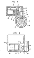
- Fig. 1 is a sectional elevation of a preferred embodiment of the steering lock of the invention;
- Fig. 2 is a top plan view of the steering lock shown in Fig. 1, the lid or cover having been omitted for more clear illustration of the inside arrangement;
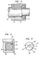
- Fig. 3 is an enlarged sectional view of the bearing arrangement for the steering shaft in the steering lock shown in Fig. 1;
- Fig. 4 is a slightly enlarged section taken along the section line A-A' shown in Fig. 2; and
- Fig. 5 is an end view of the rotator carrying the sector cam in the steering lock shown in Figs. 1 to 4.
- In the drawings, which illustrate a preferred embodiment of the steering lock of the invention, a
conventional steering shaft 10 is rotatably supported by a ball bearingunit 12 positively supported in alock housing 13. Thishousing 13 is formed with a hollowcylindrical portion 14 in which thebearing unit 12 is mounted, for example, by a pressure or push-in fit. - In the upper part of the
housing 13, aguide opening 17 is arranged in communication with the hollowcylindrical space 14 andcontainer chambers 15. The upper part of thehousing 13 is tightly and rigidly closed by alid 16 which is a removable snap-fit or pressure fit therein for the purpose of theft-prevention. - A
locking bar 18 is slidably mounted in the guide opening 17, thebar 18 being shown in Fig. 1 a its advanced and locking position in engagement with a reception recess 11 formed on thesteering shaft 10. A so-called "hanger-member" 19 is attached to thelocking bar 18 and slides in unison therewith. Thehanger member 19 may be directly fixed to thebar 18. - A
compression coil spring 20 is mounted betweenlid 16 andhanger member 19 under compression and thus urges thebar 18 to move downwards in Fig. 1. - A
member 21 called "a rotator" is held in pressure contact with thehanger member 19, as is clearly shown in Fig. 5 in side view. Thisrotator 21 acts to prevent excess or insufficient advancement of thebar 18, as will be described more fully later. - An
electric motor 22, agearing unit 23 and anoutput shaft 36 thereof are mounted in thehousing 13 as shown. Rotation is transmitted from themotor 22 through thegearing unit 23 to theoutput shaft 36. Thegearing unit 23 is housed in acasing 24 which is shown in cross-section in Fig. 4. - In the
casing 24 two diametricallyopposite openings switches former switch 34 is adapted for sensing the shaft-unlocking position of thebar 18, while thelatter switch 35 senses the shaft-locking position of thebar 18.. - When the
motor 22 is energized to rotate, output torque is transmitted therefrom through the reduction gearing 23 to theoutput shaft 36, a mechanical coupling being provided between the latter and therotator 21 to thehanger member 19 and thence to thelocking bar 18, so as to raise the latter from its locking position shown in Fig. 1 towards its unlocking upper position. - As shown in Fig. 5, the
rotator 21 is formed with asector cam 29, having a cam angle alpha betweenside slopes 31 and 32, measured around anapex 30, of substantially 15 to 150 degrees, most preferably about 90 degrees. - In the shaft-locking position, the
switch 35 is positioned nearest to a shaft-position indicator magnet (25) in or on therotator 21, or theoutput shaft 36 as shown in Fig. 4, so as to energize that switch. At the same time, theother switch 34 is remote from thesame magnet 25, so thatswitch 34 is de-energized. - When a certain switch (not shown) is turned on, the
motor 22 is rotated and motion is transmitted therefrom through the reduction gearing 23, theoutput shaft 36 and the coupling to therotator 21. Motion is further transmitted from thecam 29 of therotator 21 to thehanger member 19 which is fixedly attached to thelocking bar 18 so as to raise the latter, as indicated in Fig. 1, towards its unlocking position. - As the
bar 18 moves towards its unlocking position, themagnet 25 is brought towards its position adjacent to theswitch 34 which senses the unlocking position and de-energizes themotor 22 by causing opening of the on-off switch (not shown) for the latter. - In this way, precise locking and unlocking operations can be assured, the shape of the
sector cam 29 being of particular importance in this respect. - In place of the
aforementioned read switches
Claims (4)
Priority Applications (2)
| Application Number | Priority Date | Filing Date | Title |
|---|---|---|---|
| DE8484309099T DE3481501D1 (en) | 1984-12-27 | 1984-12-27 | KEYLESS STEERING LOCK. |
| EP19840309099 EP0185818B1 (en) | 1984-12-27 | 1984-12-27 | Keyless steering lock |
Applications Claiming Priority (1)
| Application Number | Priority Date | Filing Date | Title |
|---|---|---|---|
| EP19840309099 EP0185818B1 (en) | 1984-12-27 | 1984-12-27 | Keyless steering lock |
Publications (2)
| Publication Number | Publication Date |
|---|---|
| EP0185818A1 EP0185818A1 (en) | 1986-07-02 |
| EP0185818B1 true EP0185818B1 (en) | 1990-03-07 |
Family
ID=8192846
Family Applications (1)
| Application Number | Title | Priority Date | Filing Date |
|---|---|---|---|
| EP19840309099 Expired EP0185818B1 (en) | 1984-12-27 | 1984-12-27 | Keyless steering lock |
Country Status (2)
| Country | Link |
|---|---|
| EP (1) | EP0185818B1 (en) |
| DE (1) | DE3481501D1 (en) |
Families Citing this family (4)
| Publication number | Priority date | Publication date | Assignee | Title |
|---|---|---|---|---|
| WO1989009149A1 (en) * | 1988-03-29 | 1989-10-05 | Francis Warwick Deuchar | Improvements relating to anti-theft automobile steering security systems |
| FR2697489B1 (en) * | 1992-11-04 | 1995-02-03 | Renault | Motor vehicle steering column locking device. |
| GB9504609D0 (en) * | 1995-03-08 | 1995-04-26 | Dinse John | Locking arrangement |
| RU2176200C2 (en) * | 2000-02-29 | 2001-11-27 | Аленкин Юрий Кириллович | Vehicle ignition switch |
Family Cites Families (2)
| Publication number | Priority date | Publication date | Assignee | Title |
|---|---|---|---|---|
| JPS5854279Y2 (en) * | 1978-04-24 | 1983-12-10 | 株式会社東海理化電機製作所 | Vehicle steering lock device |
| FR2543085B1 (en) * | 1983-03-25 | 1985-06-14 | Neiman Sa | STEERING LOCK FOR MOTOR VEHICLE |
-
1984
- 1984-12-27 DE DE8484309099T patent/DE3481501D1/en not_active Expired - Lifetime
- 1984-12-27 EP EP19840309099 patent/EP0185818B1/en not_active Expired
Also Published As
| Publication number | Publication date |
|---|---|
| EP0185818A1 (en) | 1986-07-02 |
| DE3481501D1 (en) | 1990-04-12 |
Similar Documents
| Publication | Publication Date | Title |
|---|---|---|
| US5184491A (en) | Combination lock with motor-driven tumblers | |
| EP0185817A1 (en) | Steering lock arrangement | |
| US6298699B1 (en) | Electronic input and dial entry lock | |
| FI87681B (en) | ELEKTROMEKANISKT DOERRLAOS | |
| US4702095A (en) | Electro-mechanical locking device | |
| EP0267423B1 (en) | Door lock assembly for automotive vehicles | |
| US4502718A (en) | Automatic door locking/unlocking device for an automotive vehicle | |
| AU2004251188B2 (en) | Electromechanical lock cylinder | |
| EP0246702B1 (en) | Stand for displaying spectacles or spectacle frames | |
| US20060169011A1 (en) | Blocking device for a motor vehicle steering shaft | |
| EP1522659B1 (en) | Electric lock with multiple-function spring | |
| US20060169010A1 (en) | Blocking device for a motor vehicle steering shaft | |
| US5622253A (en) | Safety switch | |
| EP0373232A1 (en) | Motor driven lock control | |
| JP7649593B2 (en) | Electronic lock | |
| EP0634548B1 (en) | Locking system for vehicle doors | |
| EP0676518A2 (en) | Lock assembly actuatable by an electrical motor and/or a mechanical key | |
| US5065657A (en) | Automatic locking mechanism for the drive device of a microtome | |
| EP0185818A1 (en) | Keyless steering lock | |
| GB2173542A (en) | A device for detecting imperfect closure of a vehicle door | |
| EP0187873B1 (en) | Keyless steering-shaft lock | |
| US3973097A (en) | Control device having locking selector means | |
| US6978644B1 (en) | Locking mechanism for handcuffs | |
| US4454934A (en) | Rotatable stem and lock | |
| WO2004100082A1 (en) | Cylinder insert for a cylinder lock |
Legal Events
| Date | Code | Title | Description |
|---|---|---|---|
| PUAI | Public reference made under article 153(3) epc to a published international application that has entered the european phase |
Free format text: ORIGINAL CODE: 0009012 |
|
| AK | Designated contracting states |
Kind code of ref document: A1 Designated state(s): DE FR GB |
|
| 17P | Request for examination filed |
Effective date: 19861129 |
|
| 17Q | First examination report despatched |
Effective date: 19880224 |
|
| GRAA | (expected) grant |
Free format text: ORIGINAL CODE: 0009210 |
|
| AK | Designated contracting states |
Kind code of ref document: B1 Designated state(s): DE FR GB |
|
| REF | Corresponds to: |
Ref document number: 3481501 Country of ref document: DE Date of ref document: 19900412 |
|
| ET | Fr: translation filed | ||
| PLBE | No opposition filed within time limit |
Free format text: ORIGINAL CODE: 0009261 |
|
| STAA | Information on the status of an ep patent application or granted ep patent |
Free format text: STATUS: NO OPPOSITION FILED WITHIN TIME LIMIT |
|
| 26N | No opposition filed | ||
| PGFP | Annual fee paid to national office [announced via postgrant information from national office to epo] |
Ref country code: DE Payment date: 19920612 Year of fee payment: 8 |
|
| GBPC | Gb: european patent ceased through non-payment of renewal fee |
Effective date: 19921227 |
|
| PG25 | Lapsed in a contracting state [announced via postgrant information from national office to epo] |
Ref country code: DE Effective date: 19930901 |
|
| REG | Reference to a national code |
Ref country code: FR Ref legal event code: ST |
|
| REG | Reference to a national code |
Ref country code: GB Ref legal event code: 728C |
|
| REG | Reference to a national code |
Ref country code: FR Ref legal event code: R1 |
|
| REG | Reference to a national code |
Ref country code: FR Ref legal event code: DS |
|
| REG | Reference to a national code |
Ref country code: FR Ref legal event code: CD Ref country code: FR Ref legal event code: CA |
|
| REG | Reference to a national code |
Ref country code: GB Ref legal event code: IF02 |
|
| PGFP | Annual fee paid to national office [announced via postgrant information from national office to epo] |
Ref country code: FR Payment date: 20021210 Year of fee payment: 19 |
|
| PGFP | Annual fee paid to national office [announced via postgrant information from national office to epo] |
Ref country code: GB Payment date: 20021224 Year of fee payment: 19 |
|
| PG25 | Lapsed in a contracting state [announced via postgrant information from national office to epo] |
Ref country code: GB Free format text: LAPSE BECAUSE OF NON-PAYMENT OF DUE FEES Effective date: 20031227 |
|
| GBPC | Gb: european patent ceased through non-payment of renewal fee |
Effective date: 20031227 |
|
| PG25 | Lapsed in a contracting state [announced via postgrant information from national office to epo] |
Ref country code: FR Free format text: LAPSE BECAUSE OF NON-PAYMENT OF DUE FEES Effective date: 20031231 |
|
| REG | Reference to a national code |
Ref country code: FR Ref legal event code: ST Effective date: 20120420 |