EP0184374A2 - Disposable unitary cytology chamber and filter card for centrifugation of fluid samples and method of making same - Google Patents
Disposable unitary cytology chamber and filter card for centrifugation of fluid samples and method of making same Download PDFInfo
- Publication number
- EP0184374A2 EP0184374A2 EP85308592A EP85308592A EP0184374A2 EP 0184374 A2 EP0184374 A2 EP 0184374A2 EP 85308592 A EP85308592 A EP 85308592A EP 85308592 A EP85308592 A EP 85308592A EP 0184374 A2 EP0184374 A2 EP 0184374A2
- Authority
- EP
- European Patent Office
- Prior art keywords
- filter card
- filter
- chamber
- card
- end flange
- Prior art date
- Legal status (The legal status is an assumption and is not a legal conclusion. Google has not performed a legal analysis and makes no representation as to the accuracy of the status listed.)
- Granted
Links
Images
Classifications
-
- B—PERFORMING OPERATIONS; TRANSPORTING
- B29—WORKING OF PLASTICS; WORKING OF SUBSTANCES IN A PLASTIC STATE IN GENERAL
- B29C—SHAPING OR JOINING OF PLASTICS; SHAPING OF MATERIAL IN A PLASTIC STATE, NOT OTHERWISE PROVIDED FOR; AFTER-TREATMENT OF THE SHAPED PRODUCTS, e.g. REPAIRING
- B29C66/00—General aspects of processes or apparatus for joining preformed parts
- B29C66/50—General aspects of joining tubular articles; General aspects of joining long products, i.e. bars or profiled elements; General aspects of joining single elements to tubular articles, hollow articles or bars; General aspects of joining several hollow-preforms to form hollow or tubular articles
- B29C66/51—Joining tubular articles, profiled elements or bars; Joining single elements to tubular articles, hollow articles or bars; Joining several hollow-preforms to form hollow or tubular articles
- B29C66/53—Joining single elements to tubular articles, hollow articles or bars
- B29C66/532—Joining single elements to the wall of tubular articles, hollow articles or bars
- B29C66/5326—Joining single elements to the wall of tubular articles, hollow articles or bars said single elements being substantially flat
-
- B—PERFORMING OPERATIONS; TRANSPORTING
- B29—WORKING OF PLASTICS; WORKING OF SUBSTANCES IN A PLASTIC STATE IN GENERAL
- B29C—SHAPING OR JOINING OF PLASTICS; SHAPING OF MATERIAL IN A PLASTIC STATE, NOT OTHERWISE PROVIDED FOR; AFTER-TREATMENT OF THE SHAPED PRODUCTS, e.g. REPAIRING
- B29C65/00—Joining or sealing of preformed parts, e.g. welding of plastics materials; Apparatus therefor
- B29C65/02—Joining or sealing of preformed parts, e.g. welding of plastics materials; Apparatus therefor by heating, with or without pressure
- B29C65/08—Joining or sealing of preformed parts, e.g. welding of plastics materials; Apparatus therefor by heating, with or without pressure using ultrasonic vibrations
-
- B—PERFORMING OPERATIONS; TRANSPORTING
- B29—WORKING OF PLASTICS; WORKING OF SUBSTANCES IN A PLASTIC STATE IN GENERAL
- B29C—SHAPING OR JOINING OF PLASTICS; SHAPING OF MATERIAL IN A PLASTIC STATE, NOT OTHERWISE PROVIDED FOR; AFTER-TREATMENT OF THE SHAPED PRODUCTS, e.g. REPAIRING
- B29C65/00—Joining or sealing of preformed parts, e.g. welding of plastics materials; Apparatus therefor
- B29C65/78—Means for handling the parts to be joined, e.g. for making containers or hollow articles, e.g. means for handling sheets, plates, web-like materials, tubular articles, hollow articles or elements to be joined therewith; Means for discharging the joined articles from the joining apparatus
- B29C65/7841—Holding or clamping means for handling purposes
-
- B—PERFORMING OPERATIONS; TRANSPORTING
- B29—WORKING OF PLASTICS; WORKING OF SUBSTANCES IN A PLASTIC STATE IN GENERAL
- B29C—SHAPING OR JOINING OF PLASTICS; SHAPING OF MATERIAL IN A PLASTIC STATE, NOT OTHERWISE PROVIDED FOR; AFTER-TREATMENT OF THE SHAPED PRODUCTS, e.g. REPAIRING
- B29C66/00—General aspects of processes or apparatus for joining preformed parts
- B29C66/40—General aspects of joining substantially flat articles, e.g. plates, sheets or web-like materials; Making flat seams in tubular or hollow articles; Joining single elements to substantially flat surfaces
- B29C66/41—Joining substantially flat articles ; Making flat seams in tubular or hollow articles
- B29C66/45—Joining of substantially the whole surface of the articles
-
- B—PERFORMING OPERATIONS; TRANSPORTING
- B29—WORKING OF PLASTICS; WORKING OF SUBSTANCES IN A PLASTIC STATE IN GENERAL
- B29C—SHAPING OR JOINING OF PLASTICS; SHAPING OF MATERIAL IN A PLASTIC STATE, NOT OTHERWISE PROVIDED FOR; AFTER-TREATMENT OF THE SHAPED PRODUCTS, e.g. REPAIRING
- B29C66/00—General aspects of processes or apparatus for joining preformed parts
- B29C66/70—General aspects of processes or apparatus for joining preformed parts characterised by the composition, physical properties or the structure of the material of the parts to be joined; Joining with non-plastics material
- B29C66/74—Joining plastics material to non-plastics material
- B29C66/748—Joining plastics material to non-plastics material to natural products or their composites, not provided for in groups B29C66/742 - B29C66/746
- B29C66/7486—Paper, e.g. cardboard
-
- B—PERFORMING OPERATIONS; TRANSPORTING
- B29—WORKING OF PLASTICS; WORKING OF SUBSTANCES IN A PLASTIC STATE IN GENERAL
- B29C—SHAPING OR JOINING OF PLASTICS; SHAPING OF MATERIAL IN A PLASTIC STATE, NOT OTHERWISE PROVIDED FOR; AFTER-TREATMENT OF THE SHAPED PRODUCTS, e.g. REPAIRING
- B29C66/00—General aspects of processes or apparatus for joining preformed parts
- B29C66/80—General aspects of machine operations or constructions and parts thereof
-
- B—PERFORMING OPERATIONS; TRANSPORTING
- B29—WORKING OF PLASTICS; WORKING OF SUBSTANCES IN A PLASTIC STATE IN GENERAL
- B29C—SHAPING OR JOINING OF PLASTICS; SHAPING OF MATERIAL IN A PLASTIC STATE, NOT OTHERWISE PROVIDED FOR; AFTER-TREATMENT OF THE SHAPED PRODUCTS, e.g. REPAIRING
- B29C66/00—General aspects of processes or apparatus for joining preformed parts
- B29C66/80—General aspects of machine operations or constructions and parts thereof
- B29C66/81—General aspects of the pressing elements, i.e. the elements applying pressure on the parts to be joined in the area to be joined, e.g. the welding jaws or clamps
- B29C66/814—General aspects of the pressing elements, i.e. the elements applying pressure on the parts to be joined in the area to be joined, e.g. the welding jaws or clamps characterised by the design of the pressing elements, e.g. of the welding jaws or clamps
- B29C66/8141—General aspects of the pressing elements, i.e. the elements applying pressure on the parts to be joined in the area to be joined, e.g. the welding jaws or clamps characterised by the design of the pressing elements, e.g. of the welding jaws or clamps characterised by the surface geometry of the part of the pressing elements, e.g. welding jaws or clamps, coming into contact with the parts to be joined
- B29C66/81431—General aspects of the pressing elements, i.e. the elements applying pressure on the parts to be joined in the area to be joined, e.g. the welding jaws or clamps characterised by the design of the pressing elements, e.g. of the welding jaws or clamps characterised by the surface geometry of the part of the pressing elements, e.g. welding jaws or clamps, coming into contact with the parts to be joined comprising a single cavity, e.g. a groove
-
- B—PERFORMING OPERATIONS; TRANSPORTING
- B29—WORKING OF PLASTICS; WORKING OF SUBSTANCES IN A PLASTIC STATE IN GENERAL
- B29C—SHAPING OR JOINING OF PLASTICS; SHAPING OF MATERIAL IN A PLASTIC STATE, NOT OTHERWISE PROVIDED FOR; AFTER-TREATMENT OF THE SHAPED PRODUCTS, e.g. REPAIRING
- B29C66/00—General aspects of processes or apparatus for joining preformed parts
- B29C66/80—General aspects of machine operations or constructions and parts thereof
- B29C66/84—Specific machine types or machines suitable for specific applications
- B29C66/847—Drilling standard machine type
-
- G—PHYSICS
- G01—MEASURING; TESTING
- G01N—INVESTIGATING OR ANALYSING MATERIALS BY DETERMINING THEIR CHEMICAL OR PHYSICAL PROPERTIES
- G01N1/00—Sampling; Preparing specimens for investigation
- G01N1/28—Preparing specimens for investigation including physical details of (bio-)chemical methods covered elsewhere, e.g. G01N33/50, C12Q
- G01N1/2813—Producing thin layers of samples on a substrate, e.g. smearing, spinning-on
-
- B—PERFORMING OPERATIONS; TRANSPORTING
- B29—WORKING OF PLASTICS; WORKING OF SUBSTANCES IN A PLASTIC STATE IN GENERAL
- B29C—SHAPING OR JOINING OF PLASTICS; SHAPING OF MATERIAL IN A PLASTIC STATE, NOT OTHERWISE PROVIDED FOR; AFTER-TREATMENT OF THE SHAPED PRODUCTS, e.g. REPAIRING
- B29C66/00—General aspects of processes or apparatus for joining preformed parts
- B29C66/01—General aspects dealing with the joint area or with the area to be joined
- B29C66/05—Particular design of joint configurations
- B29C66/10—Particular design of joint configurations particular design of the joint cross-sections
- B29C66/11—Joint cross-sections comprising a single joint-segment, i.e. one of the parts to be joined comprising a single joint-segment in the joint cross-section
- B29C66/112—Single lapped joints
- B29C66/1122—Single lap to lap joints, i.e. overlap joints
-
- B—PERFORMING OPERATIONS; TRANSPORTING
- B29—WORKING OF PLASTICS; WORKING OF SUBSTANCES IN A PLASTIC STATE IN GENERAL
- B29C—SHAPING OR JOINING OF PLASTICS; SHAPING OF MATERIAL IN A PLASTIC STATE, NOT OTHERWISE PROVIDED FOR; AFTER-TREATMENT OF THE SHAPED PRODUCTS, e.g. REPAIRING
- B29C66/00—General aspects of processes or apparatus for joining preformed parts
- B29C66/01—General aspects dealing with the joint area or with the area to be joined
- B29C66/05—Particular design of joint configurations
- B29C66/302—Particular design of joint configurations the area to be joined comprising melt initiators
- B29C66/3022—Particular design of joint configurations the area to be joined comprising melt initiators said melt initiators being integral with at least one of the parts to be joined
- B29C66/30223—Particular design of joint configurations the area to be joined comprising melt initiators said melt initiators being integral with at least one of the parts to be joined said melt initiators being rib-like
-
- B—PERFORMING OPERATIONS; TRANSPORTING
- B29—WORKING OF PLASTICS; WORKING OF SUBSTANCES IN A PLASTIC STATE IN GENERAL
- B29C—SHAPING OR JOINING OF PLASTICS; SHAPING OF MATERIAL IN A PLASTIC STATE, NOT OTHERWISE PROVIDED FOR; AFTER-TREATMENT OF THE SHAPED PRODUCTS, e.g. REPAIRING
- B29C66/00—General aspects of processes or apparatus for joining preformed parts
- B29C66/80—General aspects of machine operations or constructions and parts thereof
- B29C66/81—General aspects of the pressing elements, i.e. the elements applying pressure on the parts to be joined in the area to be joined, e.g. the welding jaws or clamps
- B29C66/816—General aspects of the pressing elements, i.e. the elements applying pressure on the parts to be joined in the area to be joined, e.g. the welding jaws or clamps characterised by the mounting of the pressing elements, e.g. of the welding jaws or clamps
- B29C66/8167—Quick change joining tools or surfaces
-
- B—PERFORMING OPERATIONS; TRANSPORTING
- B29—WORKING OF PLASTICS; WORKING OF SUBSTANCES IN A PLASTIC STATE IN GENERAL
- B29C—SHAPING OR JOINING OF PLASTICS; SHAPING OF MATERIAL IN A PLASTIC STATE, NOT OTHERWISE PROVIDED FOR; AFTER-TREATMENT OF THE SHAPED PRODUCTS, e.g. REPAIRING
- B29C66/00—General aspects of processes or apparatus for joining preformed parts
- B29C66/80—General aspects of machine operations or constructions and parts thereof
- B29C66/83—General aspects of machine operations or constructions and parts thereof characterised by the movement of the joining or pressing tools
- B29C66/832—Reciprocating joining or pressing tools
- B29C66/8322—Joining or pressing tools reciprocating along one axis
-
- B—PERFORMING OPERATIONS; TRANSPORTING
- B29—WORKING OF PLASTICS; WORKING OF SUBSTANCES IN A PLASTIC STATE IN GENERAL
- B29L—INDEXING SCHEME ASSOCIATED WITH SUBCLASS B29C, RELATING TO PARTICULAR ARTICLES
- B29L2031/00—Other particular articles
- B29L2031/14—Filters
-
- G—PHYSICS
- G01—MEASURING; TESTING
- G01N—INVESTIGATING OR ANALYSING MATERIALS BY DETERMINING THEIR CHEMICAL OR PHYSICAL PROPERTIES
- G01N1/00—Sampling; Preparing specimens for investigation
- G01N1/28—Preparing specimens for investigation including physical details of (bio-)chemical methods covered elsewhere, e.g. G01N33/50, C12Q
- G01N1/2813—Producing thin layers of samples on a substrate, e.g. smearing, spinning-on
- G01N2001/2846—Cytocentrifuge method
Definitions
- THIS INVENTION relates to filter assemblies for use in the analysis of body fluids; and more particularly relates to a novel and improved unitary cytology chamber and filter card and to a method for making same for use in the centrifugation of body fluid samples.
- Centrifuges are customarily employed in the separation of cells and other solids from body fluids to permit subsequent diagnosis or analysis. Centrifuges presently in use are designed to accommodate a plurality of sample chambers and in such a way as to be capable of rapidly loading and unloading the chambers so as to facilitate more rapid and efficient sampling.
- One such centrifuge is the cytocentrifuge disclosed by Gordon in US-A-4,391,710 and EP-A-0 047 840, wherein a plurality of holders are arranged in spaced circumferential relation to one another about a common motor drive, each holder being adapted to retain an individual chamber together with a separate filter card and slide.
- each holder is made up of a channel adapted to receive a slide which is overlaid by a filter card and by a correspondingly shaped end flange at an end of the sample chamber.
- the holder includes a clamp in order to retain the assembly of the chamber, filter card and slide together and in properly aligned relation such that the filter card will properly absorb the liquid component of the sample and permit the cells and other solids to pass through an aperture in the card and be deposited onto a surface of the slide.
- an objective of the invention is to provide a unitary chamber and filter card in which the components are permanently united together in properly aligned relation and cannot be separated without destroying the interface between the two; and to provide a method for uniting these two components together that avoids any danger of contamination of the sample and offers an extremely simple but effective way of assembling the components so as to prevent their reuse and assure more rapid loading and unloading of the samples with respect to their respective holders.
- the invention consists in a unitary disposable filter unit adapted for use in the analysis of body fluids, comprising a disposable sample chamber having a liquid sample-receiving funnel, a flat solid flange member defining a support surface for a filter card and a discharge port extending from said funnel and terminating in an opening in said flange member; a filter card overlying said support surface of said flange member and including an opening therein; and securing means for permanently affixing said filter card to said support surface with said opening in said card aligned with said discharge port.
- the flange member has attachment ribs protruding from said support surface at spaced intervals therealong and embedded in said filter card.
- These attachment ribs are preferably disposed at outer peripheral edges of the flange member, which is preferably generally rectangular and has the ribs disposed adjacent to each of its corners, in facing relation to the filter card.
- attachment ribs terminate in tapered edges and define energy directors adapted for application of ultrasonic energy thereto.
- the ribs are conveniently of narrow elongated configuration.
- the invention also consists in a centrifuge having a plurality of holders mounted on a rotary carrier and each having clamping means by which a filter unit of the aforesaid construction is releasably clamped with its filter card in overlying relation to a microscope slide.
- the invention consists in the method of forming a unitary, disposable chamber and filter unit in which a chamber is provided with a liquid sample inlet and a discharge port which communicates between said inlet and an end flange, and a filter card is adapted to be positioned on said end flange with an opening therein aligned with said discharge port, characterised by the steps comprising forming energy directors in the form of protruding ribs on a flat surface of said end flange; placing a filter card in overlying relation to said end flange with the opening in said filter card aligned with a discharge port; and applying ultrasonic energy to said end flange whereby to weld said energy directors to said filter cards.
- the said energy directors are preferably spaced along opposite sides of the end surface supporting the filter card and the method is further characterised by concentrating applications of ultrasonic energy to a surface of said end flange opposite to said energy directors.
- the method includes the step of forming said energy directors as generally triangular ribs which terminate in tapered edges in facing relation to said filter card.
- the energy directors are desirably located at spaced intervals around the outer edge of said end flange said filter card being pressed against said end surface as ultrasonic energy is applied thereto.
- the method conveniently includes the step of positioning said chamber and said filter card on a jig with said end flange of said chamber in overlying relation to said filter card and with the opening in said filter card aligned with said discharge port, applying downward pressure to said chamber to press said end flange against said filter card, and positioning an ultrasonic welding horn over said chamber with spaced energy applying end surfaces of said horn disposed in contact with one surface of said end flange opposite to said energy directors.
- the centrifuge 14 comprises a series of holders 12 which are mounted in spaced circumferential relation in a common carrier plate 16 which is disposed for rotation about a vertical axis through a central drive unit including a hub, a portion of which is represented at 18.
- the drive unit may be regarded as comprised of the central hub 18 mounted on the output shaft of a drive motor, the carrier plate being fixed to the hub 18 for rotation therewith.
- the holders 12 with chambers 10 and carrier plate 16 are suspended within a lower bowl portion 20 and upper cover 21, mating peripheral edges 22 and 23 of the bowl 20 and cover 21 being interconnected and a seal 14 being interposed therebetween.
- the preferred form of cytology chamber 10 comprises a main body in the form of a flat, generally rectangular plate 28 having an end flange 30 disposed normal to and along the edge of the plate 28 and which is reinforced by generally triangular, upper and lower ends 31 and 32, respectively.
- the front surface of the flange 30 is provided with horizontally directed, slotted ledges 33 on opposite sides of the plate 28 for a purpose to be described.
- a vertically directed funnel portion 34 is contained within the body and tapers downwardly into a laterally extending discharge port 36 which is directed from the lower end of the funnel through the end flange 30 and terminates In an opening 37 surrounded by an annular sealing surface 38 projecting from exposed end surface 30' of the end flange 30.
- a cap 39 is dimensioned for releasable insertion in the upper open end of the funnel, and release vents in the form of vertical slots 35 along the inner wall of the funnel permit the escape of air when the cap 39 is in place.
- a filter card 40 is dimensioned to be coextensive with the end flange 30 and is provided with a circular opening 42 which is located to register with the annular sealing surface 38 when the filter card is aligned with and permanently attached to the end flange.
- cytology chambers 10 as above described are designed so that a liquid sample may be placed in the funnel 34 and remain there until the centrifuging operation commences, at which time the sample will be driven in a radial outward direction through the discharge port 36.
- the holder 12 is constructed and arranged for releasable insertion and clamping of the chamber therein with the funnel portion 34 positioned radially inwardly of the end flange 30 and with the funnel 34 disposed in a generally upright position.
- the holder 12 is comprised of a -generally U-shaped channel 46 having opposite side plates 47, a common web 48 interconnecting the side plates, and a locating lug or end stop 49.
- a generally U-shaped clamping member 50 is disposed in surrounding relation to the midsection of the clamping member, the clamping member having opposite, generally triangular sidewalls 52 with inturned lugs 53 at the lower extremities of the sidewalls 52 to overlie the downwardly tapered sides 47 of the channel 46 and engage the ledges 33.
- a pivot rod 54 extends across the channel member 50 through the sidewalls 52 and is spring-loaded by a torsion spring 55 so as to permit rocking movement of the clamp 50 relative to the channel 46 in a manner to be described.
- a release screw 58 is threaded into a boss 59 on the clamping member 50 so that its leading end is engageable with the rear face of the web 48 of the channel to cause the clamping member 50 to rock or tilt about the pivot rod 54 in opposition to the torsion of the spring element 55 on the pivot rod.
- a microscope slide 41 is assembled or placed against the filter card 40.
- the slide 41 is a rectangular gloss slide dimensioned to correspond to the size of the filter card 40 and is inserted along with the filter card 40 and end flange 30 of the chamber by sliding downwardly through the channel 46 until the lower edges of the end flange 30, filter card 40 and slide 41 abut the forwardly directed end stop 49 at the lower edge of the channel 46.
- the inturned lugs 53 will engage opposite sides of the end flange 30.
- the holder 12 seats in the carrier plate 16 so that it has limited freedom to rock about a horizontal axis defined by the pivot rod 54 having its ends seating in notches in flanges bounding the aperture in the carrier plate through which the holder 12 projects.
- the arrangement is such that prior to commencement of the centrifuging operation, while forming no part of the present invention, the assembly of holder 12, chamber 10, card 40 and slide 41 takes up an attitude in which the chamber 10 and its funnel 34 is tilted or tipped somewhat downwardly and the open end of the port is tipped upwardly so that any liquid in the funnel which passes into the discharge port 46 will remain at the closed end of the port.
- the centrifugal force imparted to the holder will cause the holder and chamber assembly to rock back into a horizontal position as illustrated and simultaneously to force the liquid to flow from the funnel through the discharge port and through the matched openings at the open end of the discharge port and the filter card into direct contact with the exposed surface of the slide.
- the filter card will absorb the liquid contents of the sample while solid matter will be deposited on the surface of the slide.
- the normally exposed end surface 30' of the end flange 30 is formed with narrow elongated ribs 60 which protrude a limited distance away from the end surface 30' and converge into tapered or pointed edges 62.
- Each rib 60 is located to extend in closely spaced parallel relation to opposite side edges of the end flange 30 and to protrude outwardly therefrom for a limited distance which is less than the thickness of the filter card 40.
- the annular sealing flange or surface 38 is formed in surrounding relation to the open end of the port 36 and protrudes from the end surface a distance slightly greater than that of the ribs.
- the ribs are formed out of the material on the end flange, each preferably being of a length of approximately one-fifth of the total length of the end flange and located relatively near the four corners of the end flange but away from the central opening.
- the ribs as described define energy directors to facilitate attachment of the filter card thereto when subjected to ultrasonic welding.
- welding is accomplished by application of frequencies in the ultrasonic range while simultaneously pressing the filter card against the end flange whereby the ultrasonic energy is concentrated at the tapered edges 62 of the ribs 60 to cause them to become molten and to bond firmly to the paper fibres of the filter card.
- the ribs 60 are locked or firmly embedded into the surface of the filter card without otherwise altering the characteristics of the filter.
- the mere application of ultrasonic energy is insufficient to secure the filter card to the end flange, energy directors at appropriately spaced intervals being necessary to permanently affix or attach the filter card to the end flange as described.
- This form of positive attachment achieves more accurate alignment between the card and end flange so as to assure that the openings between the port and filter card are aligned for unobstructed flow of the liquid therethrough and greatly facilitates loading of the chamber and attached filter card in place within the holder assembly preliminary to each centrifuge operation.
- the attached filter card avoids reuse of the card or assembly, since any attempt to remove the filter card will leave substantial segments in surrounding relation to the ribs and preclude proper placement and positioning of a fresh filter card over the end flange of the chamber. Attachment in the manner described also minimizes any danger of smearing or loss of the deposit on the slide when the holder assembly is removed from the carrier plate and the slide is separated from the filter card and chamber for analysis.
- the chamber 10 is inserted within a cavity 65 of a welding horn 80.
- a filter card 40 is placed into position on a jig 82 beneath the exposed or lower end surface of the flange 30.
- the weldinq horn 80 is specifically designed to he of generally U-shaped configuration with downwardly directed legs G7 fermire atinq in lower end surfaces 68, the horn 80 being superimposed over the chamber 10 until the end surfaces 68 are disposed in close proximity to the front or upper surface of the end flange 30 on the side opposite to the filter card 40.
- Ultrasonic energy is then applied to the horn via a standard welding unit as generally designated at W for a very short duration or interval of time on the order of less than one second which is more than sufficient to heat the energy directors 60 to a level such as to cause their edges 62 to become molten and to bond to the filter without burning the filter paper.
- the horn is then removed followed by removal of the completed chamber assembly from the cavity.
- a preferred form of ultrasonic welder is a Model 8400 horn with a gold booster manufactured and sold by Branson Sonic Power Company of Dansbury, Connecticut.
- tapered edges 62 of the energy directors or ribs 60 permit sufficient concentration of heat to cause the edges to be rapidly heated to a molten state without burning the filter card itself.
- other cross-sectional configurations may be adopted or employed to accomplish the same end; and, for example, the cross-sectional configuration of the ribs may be rounded or provided with multiple edges so long as there is sufficient concentration of heat to cause the desired bonding without unduly heating the paper fibres of the filter card.
- the location of the ribs may be varied to some extent, bearing in mind that the ultrasonic welder must be applied to the surface of the end flange directly opposite to the ribs in order to most rapidly direct the energy into the ribs 60 for welding purposes and therefore are most desirably located along opposite side edges so as to be aligned opposite to the points of contact between the ribs 60 and filter card 40.
Landscapes
- Mechanical Engineering (AREA)
- Engineering & Computer Science (AREA)
- Chemical & Material Sciences (AREA)
- Life Sciences & Earth Sciences (AREA)
- Physics & Mathematics (AREA)
- Health & Medical Sciences (AREA)
- Analytical Chemistry (AREA)
- Biochemistry (AREA)
- General Health & Medical Sciences (AREA)
- General Physics & Mathematics (AREA)
- Immunology (AREA)
- Pathology (AREA)
- Composite Materials (AREA)
- Sampling And Sample Adjustment (AREA)
- Centrifugal Separators (AREA)
Abstract
Description
- THIS INVENTION relates to filter assemblies for use in the analysis of body fluids; and more particularly relates to a novel and improved unitary cytology chamber and filter card and to a method for making same for use in the centrifugation of body fluid samples.
- Centrifuges are customarily employed in the separation of cells and other solids from body fluids to permit subsequent diagnosis or analysis. Centrifuges presently in use are designed to accommodate a plurality of sample chambers and in such a way as to be capable of rapidly loading and unloading the chambers so as to facilitate more rapid and efficient sampling. One such centrifuge is the cytocentrifuge disclosed by Gordon in US-A-4,391,710 and EP-A-0 047 840, wherein a plurality of holders are arranged in spaced circumferential relation to one another about a common motor drive, each holder being adapted to retain an individual chamber together with a separate filter card and slide. Specifically, each holder is made up of a channel adapted to receive a slide which is overlaid by a filter card and by a correspondingly shaped end flange at an end of the sample chamber. The holder includes a clamp in order to retain the assembly of the chamber, filter card and slide together and in properly aligned relation such that the filter card will properly absorb the liquid component of the sample and permit the cells and other solids to pass through an aperture in the card and be deposited onto a surface of the slide.
- As noted in the Gordon Patents, a problem associated with prior art arrangements is the assembly operation to be carried out in the installation of the sample chambers in conjunction with the rotating carrier of the centrifuge and specifically to achieve proper alignment between the chamber, filter card and receiving surface of the slide. Such arrangements were difficult to assemble and manipulate especially when the material being centrifuged must be handled under conditions of containment in order to prevent the escape of toxic or noxious matter. Even with the improvements of the Gordon Patents, it is necessary to preassemble each chamber, filter card and slide as a preliminary to mounting in the holder. Upon completion of the centrifuging operation and removal of the assembled components and disassembly of same to recover the sample to be examined, the holders and chambers must be cleaned and sterilized individually for subsequent reuse.
- Notwithstanding that the centrifuge disclosed in the Gordon Patents offers definite advantages and improvements over the prior art in the handling and sampling of body fluids, there exists the need for further improvements to the steps of preassembly as a preliminary to placement in the holder, and also to assure accurate alignment between the elements and, most importantly, to preclude reuse of the cytology chamber and/or the filter card. The latter feature is particularly important in the handling of body fluids containing certain diseases where it is vital that the chamber or filter card not be reused after a particular sampling operation. Because joining of a cytology chamber and a filter card together as a unitary assembly would avoid any temptation on the part of the operator to reuse either or both in subsequent sampling operations, an objective of the invention is to provide a unitary chamber and filter card in which the components are permanently united together in properly aligned relation and cannot be separated without destroying the interface between the two; and to provide a method for uniting these two components together that avoids any danger of contamination of the sample and offers an extremely simple but effective way of assembling the components so as to prevent their reuse and assure more rapid loading and unloading of the samples with respect to their respective holders.
- Other representative U.S. Patents in this field are US-A-4,265,762 (Brenholt); US-A-4,344,562 (Ricci); and US-A-4,357,240 (Mehra et al). However, none suggests or discloses a manner and means by which a filter card may be permanently affixed to an end flange on a chamber and in properly aligned relation so as to form a disposable unit and in such a way as to preclude reuse of the assembly in the manner devised according to the present invention.
- In one aspect, the invention consists in a unitary disposable filter unit adapted for use in the analysis of body fluids, comprising a disposable sample chamber having a liquid sample-receiving funnel, a flat solid flange member defining a support surface for a filter card and a discharge port extending from said funnel and terminating in an opening in said flange member; a filter card overlying said support surface of said flange member and including an opening therein; and securing means for permanently affixing said filter card to said support surface with said opening in said card aligned with said discharge port.
- Desirably the flange member has attachment ribs protruding from said support surface at spaced intervals therealong and embedded in said filter card. These attachment ribs are preferably disposed at outer peripheral edges of the flange member, which is preferably generally rectangular and has the ribs disposed adjacent to each of its corners, in facing relation to the filter card.
- Preferably the attachment ribs terminate in tapered edges and define energy directors adapted for application of ultrasonic energy thereto. The ribs are conveniently of narrow elongated configuration.
- The invention also consists in a centrifuge having a plurality of holders mounted on a rotary carrier and each having clamping means by which a filter unit of the aforesaid construction is releasably clamped with its filter card in overlying relation to a microscope slide.
- In another aspect the invention consists in the method of forming a unitary, disposable chamber and filter unit in which a chamber is provided with a liquid sample inlet and a discharge port which communicates between said inlet and an end flange, and a filter card is adapted to be positioned on said end flange with an opening therein aligned with said discharge port, characterised by the steps comprising forming energy directors in the form of protruding ribs on a flat surface of said end flange; placing a filter card in overlying relation to said end flange with the opening in said filter card aligned with a discharge port; and applying ultrasonic energy to said end flange whereby to weld said energy directors to said filter cards.
- The said energy directors are preferably spaced along opposite sides of the end surface supporting the filter card and the method is further characterised by concentrating applications of ultrasonic energy to a surface of said end flange opposite to said energy directors.
- Preferably the method includes the step of forming said energy directors as generally triangular ribs which terminate in tapered edges in facing relation to said filter card. The energy directors are desirably located at spaced intervals around the outer edge of said end flange said filter card being pressed against said end surface as ultrasonic energy is applied thereto.
- The method conveniently includes the step of positioning said chamber and said filter card on a jig with said end flange of said chamber in overlying relation to said filter card and with the opening in said filter card aligned with said discharge port, applying downward pressure to said chamber to press said end flange against said filter card, and positioning an ultrasonic welding horn over said chamber with spaced energy applying end surfaces of said horn disposed in contact with one surface of said end flange opposite to said energy directors.
- The invention is further described with reference to the accompanying drawings, in which:
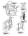
- FIGURE I is a cross-sectional view illustrating the disposition and mounting of a preferred form of chamber and filter card assembly in a cytocentrifuge in accordance with the present invention;
- FIGURE 2 is an exploded view of a preferred form of cytology chamber and filter card preliminary to ultrasonically welding the filter card to the end surface of the chamber;
- FIGURE 3 is a top plan view of the assembled cytology chamber and filter card shown in Figure 2;
- FIGURE 4 is a front view of the cytology chamber and illustrates in dotted form the placement of energy directors on the end surface thereof;
- FIGURE 5 is a cross-sectional view taken about lines 5-5 of Figure 4;
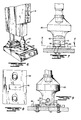
- FIGURE 6 is a somewhat perspective view illustrating a welding unit employed in assembling a filter card and cytology chamber together;
- FIGURE 7 is an enlarged view in more detail of the welding unit illustrated in Figure 6 and with the welding horn shown partially in section;
- FIGURE 8 is a view taken about lines 8-8 of Figure 7 and illustrating the placement of the filter card on a portion of a jig; and
- FIGURE 9 is an end view partially in section of the welder unit and jig shown in Figure 7.
- There is shown by way of illustrative example in Figure I a preferred form of assembly of
chamber 10 and filter card installed in aholder 12 of a cytocentrifuge, a portion of which is generally designated at 14. As a setting for the present invention, the centrifuge 14 comprises a series ofholders 12 which are mounted in spaced circumferential relation in acommon carrier plate 16 which is disposed for rotation about a vertical axis through a central drive unit including a hub, a portion of which is represented at 18. For purposes of illustration, the drive unit may be regarded as comprised of thecentral hub 18 mounted on the output shaft of a drive motor, the carrier plate being fixed to thehub 18 for rotation therewith. Theholders 12 withchambers 10 andcarrier plate 16 are suspended within alower bowl portion 20 andupper cover 21, matingperipheral edges bowl 20 andcover 21 being interconnected and a seal 14 being interposed therebetween. - As a preliminary to describing the construction of a
typical holder 12, it should be noted that the preferred form ofcytology chamber 10 comprises a main body in the form of a flat, generallyrectangular plate 28 having anend flange 30 disposed normal to and along the edge of theplate 28 and which is reinforced by generally triangular, upper andlower ends flange 30 is provided with horizontally directed, slottedledges 33 on opposite sides of theplate 28 for a purpose to be described. A vertically directedfunnel portion 34 is contained within the body and tapers downwardly into a laterally extendingdischarge port 36 which is directed from the lower end of the funnel through theend flange 30 and terminates In anopening 37 surrounded by anannular sealing surface 38 projecting from exposed end surface 30' of theend flange 30. Acap 39 is dimensioned for releasable insertion in the upper open end of the funnel, and release vents in the form ofvertical slots 35 along the inner wall of the funnel permit the escape of air when thecap 39 is in place. Afilter card 40 is dimensioned to be coextensive with theend flange 30 and is provided with acircular opening 42 which is located to register with theannular sealing surface 38 when the filter card is aligned with and permanently attached to the end flange. - Broadly,
cytology chambers 10 as above described are designed so that a liquid sample may be placed in thefunnel 34 and remain there until the centrifuging operation commences, at which time the sample will be driven in a radial outward direction through thedischarge port 36. For this purpose, theholder 12 is constructed and arranged for releasable insertion and clamping of the chamber therein with thefunnel portion 34 positioned radially inwardly of theend flange 30 and with thefunnel 34 disposed in a generally upright position. Theholder 12 is comprised of a -generally U-shapedchannel 46 havingopposite side plates 47, acommon web 48 interconnecting the side plates, and a locating lug orend stop 49. A generally U-shapedclamping member 50 is disposed in surrounding relation to the midsection of the clamping member, the clamping member having opposite, generallytriangular sidewalls 52 with inturned lugs 53 at the lower extremities of thesidewalls 52 to overlie the downwardly taperedsides 47 of thechannel 46 and engage the ledges 33. Apivot rod 54 extends across thechannel member 50 through thesidewalls 52 and is spring-loaded by a torsion spring 55 so as to permit rocking movement of theclamp 50 relative to thechannel 46 in a manner to be described. Arelease screw 58 is threaded into aboss 59 on theclamping member 50 so that its leading end is engageable with the rear face of theweb 48 of the channel to cause the clampingmember 50 to rock or tilt about thepivot rod 54 in opposition to the torsion of the spring element 55 on the pivot rod. - In the installation of the chamber assembly into the holder, a
microscope slide 41 is assembled or placed against thefilter card 40. - Preferably, the
slide 41 is a rectangular gloss slide dimensioned to correspond to the size of thefilter card 40 and is inserted along with thefilter card 40 andend flange 30 of the chamber by sliding downwardly through thechannel 46 until the lower edges of theend flange 30,filter card 40 and slide 41 abut the forwardly directedend stop 49 at the lower edge of thechannel 46. In this relation, the inturned lugs 53 will engage opposite sides of theend flange 30. Theholder 12 seats in thecarrier plate 16 so that it has limited freedom to rock about a horizontal axis defined by thepivot rod 54 having its ends seating in notches in flanges bounding the aperture in the carrier plate through which theholder 12 projects. The arrangement is such that prior to commencement of the centrifuging operation, while forming no part of the present invention, the assembly ofholder 12,chamber 10,card 40 andslide 41 takes up an attitude in which thechamber 10 and itsfunnel 34 is tilted or tipped somewhat downwardly and the open end of the port is tipped upwardly so that any liquid in the funnel which passes into thedischarge port 46 will remain at the closed end of the port. Under rotation, the centrifugal force imparted to the holder will cause the holder and chamber assembly to rock back into a horizontal position as illustrated and simultaneously to force the liquid to flow from the funnel through the discharge port and through the matched openings at the open end of the discharge port and the filter card into direct contact with the exposed surface of the slide. The filter card will absorb the liquid contents of the sample while solid matter will be deposited on the surface of the slide. - Having considered the manner in which the holder and chamber assembly is employed in the recovery of a sample, reference is now made in more detail to the construction and arrangement of the
end flange 30 andfilter card 40 and the method of joining or permanently affixing the filter card to the end flange. Referring specifically to Figures 2 to 5, the normally exposed end surface 30' of theend flange 30 is formed with narrowelongated ribs 60 which protrude a limited distance away from the end surface 30' and converge into tapered orpointed edges 62. Eachrib 60 is located to extend in closely spaced parallel relation to opposite side edges of theend flange 30 and to protrude outwardly therefrom for a limited distance which is less than the thickness of thefilter card 40. Similarly, the annular sealing flange orsurface 38 is formed in surrounding relation to the open end of theport 36 and protrudes from the end surface a distance slightly greater than that of the ribs. Preferably, the ribs are formed out of the material on the end flange, each preferably being of a length of approximately one-fifth of the total length of the end flange and located relatively near the four corners of the end flange but away from the central opening. The ribs as described define energy directors to facilitate attachment of the filter card thereto when subjected to ultrasonic welding. - In the preferred method of joining the
filter card 40 to theend flange 30, welding is accomplished by application of frequencies in the ultrasonic range while simultaneously pressing the filter card against the end flange whereby the ultrasonic energy is concentrated at thetapered edges 62 of theribs 60 to cause them to become molten and to bond firmly to the paper fibres of the filter card. In this way, theribs 60 are locked or firmly embedded into the surface of the filter card without otherwise altering the characteristics of the filter. The mere application of ultrasonic energy is insufficient to secure the filter card to the end flange, energy directors at appropriately spaced intervals being necessary to permanently affix or attach the filter card to the end flange as described. This form of positive attachment achieves more accurate alignment between the card and end flange so as to assure that the openings between the port and filter card are aligned for unobstructed flow of the liquid therethrough and greatly facilitates loading of the chamber and attached filter card in place within the holder assembly preliminary to each centrifuge operation. Most importantly, the attached filter card avoids reuse of the card or assembly, since any attempt to remove the filter card will leave substantial segments in surrounding relation to the ribs and preclude proper placement and positioning of a fresh filter card over the end flange of the chamber. Attachment in the manner described also minimizes any danger of smearing or loss of the deposit on the slide when the holder assembly is removed from the carrier plate and the slide is separated from the filter card and chamber for analysis. - In the preferred method of welding and affixing a
filter card 40 to anend flange 30 ofchamber 10, as illustrated in Figures 6 to 9, thechamber 10 is inserted within acavity 65 of awelding horn 80. Afilter card 40 is placed into position on ajig 82 beneath the exposed or lower end surface of theflange 30. Theweldinq horn 80 is specifically designed to he of generally U-shaped configuration with downwardly directed legs G7 fermire atinq in lower end surfaces 68, thehorn 80 being superimposed over thechamber 10 until the end surfaces 68 are disposed in close proximity to the front or upper surface of theend flange 30 on the side opposite to thefilter card 40.Slots 70 are formed in the end surfaces 68 of thehorn 80 to register with theledges 33 on theend flange 30 thereby permitting the end surfaces 68 of the horn to bear against the flat surface of the flange. Ultrasonic energy is then applied to the horn via a standard welding unit as generally designated at W for a very short duration or interval of time on the order of less than one second which is more than sufficient to heat theenergy directors 60 to a level such as to cause theiredges 62 to become molten and to bond to the filter without burning the filter paper. The horn is then removed followed by removal of the completed chamber assembly from the cavity. A preferred form of ultrasonic welder is a Model 8400 horn with a gold booster manufactured and sold by Branson Sonic Power Company of Dansbury, Connecticut. It should be appreciated that the taperededges 62 of the energy directors orribs 60 permit sufficient concentration of heat to cause the edges to be rapidly heated to a molten state without burning the filter card itself. In this relation, other cross-sectional configurations may be adopted or employed to accomplish the same end; and, for example, the cross-sectional configuration of the ribs may be rounded or provided with multiple edges so long as there is sufficient concentration of heat to cause the desired bonding without unduly heating the paper fibres of the filter card. Moreover, the location of the ribs may be varied to some extent, bearing in mind that the ultrasonic welder must be applied to the surface of the end flange directly opposite to the ribs in order to most rapidly direct the energy into theribs 60 for welding purposes and therefore are most desirably located along opposite side edges so as to be aligned opposite to the points of contact between theribs 60 andfilter card 40. - The features disclosed in the foregoing description, in the following claims and/or in the accompanying drawings may, both separately and in any combination thereof, be material for realising the invention in diverse forms thereof.
Claims (12)
- I. A unitary disposable filter unit adapted for use in the analysis of body fluids, comprising a disposable sample chamber having a liquid sample-receiving funnel, a flat solid flange member defining a support surface for a filter card and a discharge port extending from said funnel and terminating in an opening in said flange member; a filter card overlying said support surface of said flange member and including an opening therein; characterised by securing means permanently affixing said filter card to said support surface with said opening in said card aligned with said discharge port.
- 2. A filter unit according to claim I, wherein said flange member has attachment ribs protruding from said support surface at spaced intervals therealong and embedded in said filter card.
- 3. A filter unit according to claim 2, wherein said ribs on said flange member are disposed at outer peripheral edges of said flange member.
- 4. A filter unit according to claim 3, wherein said flange member is generally rectangular and said ribs are disposed adjacent to each corner of said flange member in facing relation to said filter card.
- 5. A filter unit according to any one of claims 2 to 4, wherein said ribs terminate in tapered edges and define energy directors adapted for application of ultrasonic energy thereto.
- 6. A filter unit according to claim 5, wherein said ribs are of narrow elongated configuration and are bonded to corresponding corners of said filter card.
- 7. A centrifuge having a plurality of holders mounted on a rotating carrier, each said holder having clamping means for releasably receiving a cytology chamber, a filter card and a microscope slide therein, characterised by a filter unit according to any one of claims I to 6 disposed in each said holder to constitute the cytology chamber and filter card and positioned so that said clamping means releasably clamp said slide in overlying relation to the filter card of the filter unit.
- 8. The method of forming a unitary, disposable chamber and filter unit in which a chamber is provided with a liquid sample inlet and a discharge port which communicates between said inlet and an end flange, and a filter card is adapted to be positioned on said end flange with an opening therein aligned with said discharge port, characterised by the steps comprising forming energy directors in the form of protruding ribs on a flat surface of said end flange; placing a filter card in overlying relation to said end flange with the opening in said filter card aligned with a discharge port; and applying ultrasonic energy to said end flange whereby to weld said energy directors to said filter cards.
- 9. A method according to claim 8, wherein said energy directors are spaced along opposite sides of said end surface supporting said filter card and further characterised by concentrating applications of ultrasonic energy to a surface of said end flange opposite to said energy directors.
- 10. A method according to claim 8 or 9, including the step of forming said energy directors as generally triangular ribs which terminate in tapered edges in facing relation to said filter card.
- II. A method according to claim 8, 9 or 10, further characterised by locating said energy directors at spaced intervals around the outer edge of said end flange and pressing said filter card against said end surface as ultrasonic energy is applied thereto.
- 12. A method according to any one of claims 9 to 11, including the step of positioning said chamber and said filter card on a jig with said end flange of said chamber in overlying relation to said filter card and with the opening in said filter card aligned with said discharge port, applying downward pressure to said chamber to press said end flange against said filter card, and positioning an ultrasonic welding horn over said chamber with spaced energy applying end surfaces of said horn disposed in contact with one surface of said end flange opposite to said energy directors.
Applications Claiming Priority (2)
| Application Number | Priority Date | Filing Date | Title |
|---|---|---|---|
| US678262 | 1984-12-05 | ||
| US06/678,262 US4678579A (en) | 1984-12-05 | 1984-12-05 | Disposable unitary cytology chamber and filter card for centrifugation of fluid samples and method of making same |
Publications (3)
| Publication Number | Publication Date |
|---|---|
| EP0184374A2 true EP0184374A2 (en) | 1986-06-11 |
| EP0184374A3 EP0184374A3 (en) | 1988-02-03 |
| EP0184374B1 EP0184374B1 (en) | 1993-04-14 |
Family
ID=24722085
Family Applications (1)
| Application Number | Title | Priority Date | Filing Date |
|---|---|---|---|
| EP85308592A Expired - Lifetime EP0184374B1 (en) | 1984-12-05 | 1985-11-26 | Disposable unitary cytology chamber and filter card for centrifugation of fluid samples and method of making same |
Country Status (5)
| Country | Link |
|---|---|
| US (2) | US4678579A (en) |
| EP (1) | EP0184374B1 (en) |
| JP (1) | JPH0713589B2 (en) |
| DE (1) | DE3587267T2 (en) |
| GB (1) | GB2168615B (en) |
Cited By (2)
| Publication number | Priority date | Publication date | Assignee | Title |
|---|---|---|---|---|
| EP0880021A1 (en) * | 1997-05-23 | 1998-11-25 | Shandon Scientific Limited | Assembly for centrifugal preparation of cytological specimens |
| WO2004063721A1 (en) | 2003-01-16 | 2004-07-29 | Thermo Shandon Limited | Centrifugation device |
Families Citing this family (17)
| Publication number | Priority date | Publication date | Assignee | Title |
|---|---|---|---|---|
| GB2184837B (en) * | 1985-11-14 | 1990-08-22 | Tiyoda Seisakusho Kk | Cell for placing solid matters on a slide glass under centrifugal force |
| US5132088A (en) * | 1988-11-17 | 1992-07-21 | Kabushiki Kaisha Nittec | Automatic medical sampling device |
| GB2291601B (en) * | 1991-11-05 | 1996-09-11 | Wescor Inc | Improved cytocentrifugation device |
| US5252228A (en) * | 1991-11-05 | 1993-10-12 | Wescor, Inc. | Cytocentrifugation device, apparatus, and method |
| DE9214534U1 (en) * | 1992-10-27 | 1993-11-25 | Fa. Andreas Hettich, 78532 Tuttlingen | Centrifugation chamber with removable clamping plate |
| US5403415A (en) * | 1993-11-17 | 1995-04-04 | Abaxis, Inc. | Method and device for ultrasonic welding |
| US5470758A (en) * | 1994-12-14 | 1995-11-28 | Shandon, Inc. | Large cytology sample chamber for distributing material onto a microscope slide |
| WO1998015401A1 (en) * | 1996-10-08 | 1998-04-16 | Toyota Jidosha Kabushiki Kaisha | Method and apparatus for welding hard resin product to substrate, method of manufacturing window glass and window glass |
| US5952239A (en) * | 1997-06-12 | 1999-09-14 | Shandon, Inc. | Cytology chamber with port to receive collection bottle and method of use |
| US5942129A (en) * | 1997-07-17 | 1999-08-24 | Shandon, Inc. | Cytology chamber with separate leg for fixative |
| GB2364932B (en) * | 2000-07-20 | 2003-07-23 | Peter Anthony Crouch | Evidence collection device and method |
| US6866640B2 (en) * | 2001-03-30 | 2005-03-15 | Becton, Dickinson And Company | Adaptor for use with point-of-care testing cartridge |
| US20070009389A1 (en) * | 2005-07-08 | 2007-01-11 | Antti Seppo | Slide deposition chamber |
| JP2007253177A (en) * | 2006-03-22 | 2007-10-04 | Denso Corp | Ultrasonic bonding method, ultrasonic bonding apparatus and ultrasonic bonded pipe |
| US7758816B2 (en) * | 2007-03-01 | 2010-07-20 | Wescor Inc. | Large area cytocentrifuge sample chamber |
| US8257667B2 (en) * | 2009-09-15 | 2012-09-04 | Biomedical Polymers, Inc. | Cytocentrifuge sample container holder and support device |
| CN102794906B (en) * | 2012-08-10 | 2014-09-24 | 常熟市汽车饰件股份有限公司 | Ultrasonic welding device and production method thereof for welding automobile plaque |
Family Cites Families (11)
| Publication number | Priority date | Publication date | Assignee | Title |
|---|---|---|---|---|
| US4137573A (en) * | 1976-03-02 | 1979-02-06 | Kroeger Daniel E | Urine specimen collector |
| US4062781A (en) * | 1976-06-04 | 1977-12-13 | Whatman Reeve Angel Limited | Disposable filter with interchangeable end elements |
| US4169751A (en) * | 1978-05-30 | 1979-10-02 | Eastman Kodak Company | High frequency bonding with concentrators |
| US4265762A (en) * | 1978-11-24 | 1981-05-05 | Donaldson Company, Inc. | Filter assembly for use in the filtration of medical treatment liquids |
| US4344562A (en) * | 1979-02-01 | 1982-08-17 | Andrew Ricci | Centrifuge cell collector apparatus |
| US4423699A (en) * | 1979-02-28 | 1984-01-03 | E. I. Du Pont De Nemours & Co. | Centrifuge rotor apparatus for preparing particle spreads |
| ATE12024T1 (en) * | 1980-09-15 | 1985-03-15 | Shandon Southern Prod | CYTO CENTRIFUGE. |
| US4357240A (en) * | 1981-02-27 | 1982-11-02 | Sybron Corporation | Disposable, one-piece filter unit |
| US4448207A (en) * | 1981-11-03 | 1984-05-15 | Vital Metrics, Inc. | Medical fluid measuring system |
| JPS60103905A (en) * | 1983-11-10 | 1985-06-08 | ワイケイケイ株式会社 | Upper stop part molding method of concealed slide fastener |
| US4572753A (en) * | 1984-07-12 | 1986-02-25 | The Coca-Cola Company | Method of ultrasonic welding and apparatus therefor |
-
1984
- 1984-12-05 US US06/678,262 patent/US4678579A/en not_active Expired - Lifetime
-
1985
- 1985-11-26 DE DE8585308592T patent/DE3587267T2/en not_active Expired - Lifetime
- 1985-11-26 EP EP85308592A patent/EP0184374B1/en not_active Expired - Lifetime
- 1985-11-26 GB GB08529071A patent/GB2168615B/en not_active Expired
- 1985-12-05 JP JP60274289A patent/JPH0713589B2/en not_active Expired - Lifetime
-
1987
- 1987-03-02 US US07/020,233 patent/US4729778A/en not_active Expired - Lifetime
Cited By (5)
| Publication number | Priority date | Publication date | Assignee | Title |
|---|---|---|---|---|
| EP0880021A1 (en) * | 1997-05-23 | 1998-11-25 | Shandon Scientific Limited | Assembly for centrifugal preparation of cytological specimens |
| US6162401A (en) * | 1997-05-23 | 2000-12-19 | Shandon Scientific Limited | Cytofunnel arrangement |
| WO2004063721A1 (en) | 2003-01-16 | 2004-07-29 | Thermo Shandon Limited | Centrifugation device |
| CN100419405C (en) * | 2003-01-16 | 2008-09-17 | 特莫香顿有限公司 | centrifugal device |
| US7628955B2 (en) | 2003-01-16 | 2009-12-08 | Thermo Shandon Limited | Centrifugation device |
Also Published As
| Publication number | Publication date |
|---|---|
| US4678579A (en) | 1987-07-07 |
| EP0184374A3 (en) | 1988-02-03 |
| GB2168615B (en) | 1988-09-14 |
| EP0184374B1 (en) | 1993-04-14 |
| JPH0713589B2 (en) | 1995-02-15 |
| DE3587267T2 (en) | 1993-07-29 |
| US4729778A (en) | 1988-03-08 |
| GB8529071D0 (en) | 1986-01-02 |
| GB2168615A (en) | 1986-06-25 |
| DE3587267D1 (en) | 1993-05-19 |
| JPS61147128A (en) | 1986-07-04 |
Similar Documents
| Publication | Publication Date | Title |
|---|---|---|
| EP0184374B1 (en) | Disposable unitary cytology chamber and filter card for centrifugation of fluid samples and method of making same | |
| US4391710A (en) | Cytocentrifuge | |
| US4534863A (en) | Centrifugal filtering device and filter unit therefor | |
| EP0213618B1 (en) | Improved combined washer and aspirator | |
| US6162401A (en) | Cytofunnel arrangement | |
| EP0158463A2 (en) | Ultrafiltration separator | |
| US5380435A (en) | Liquid absorption pad for cytocentrifugation device | |
| EP0584332B1 (en) | Apparatus for collection and transfer of particles and manufacture thereof | |
| US4827779A (en) | Cartridge personal sampling impactor | |
| US20170120259A1 (en) | Device for constant-volume collection using centrifugation or for further storage | |
| EP0045368B1 (en) | A chamber block having a supernatant collection receptacle therein | |
| JP2686608B2 (en) | Reagent container, manufacturing method thereof, and clinical apparatus | |
| JPH05116221A (en) | Nest used for welding plastic tubes | |
| US5409832A (en) | Membrane holder for use in an assay device | |
| US4387992A (en) | Rotatable cuvette array | |
| EP0045369B1 (en) | A chamber block with a removable supernatant collection vial | |
| EP0801590B1 (en) | Filtration apparatus | |
| AU609522B2 (en) | Cell block collection method and apparatus | |
| EP0211155A2 (en) | Disposable filter unit | |
| US5942129A (en) | Cytology chamber with separate leg for fixative | |
| JP3765680B2 (en) | Blood filter | |
| GB2291601A (en) | Cytocentrifugation filter pad | |
| AU2023352861A2 (en) | Film seal assembly and single lid assay cartridge and associated methods |
Legal Events
| Date | Code | Title | Description |
|---|---|---|---|
| PUAI | Public reference made under article 153(3) epc to a published international application that has entered the european phase |
Free format text: ORIGINAL CODE: 0009012 |
|
| AK | Designated contracting states |
Kind code of ref document: A2 Designated state(s): BE CH DE FR GB IT LI LU NL |
|
| PUAL | Search report despatched |
Free format text: ORIGINAL CODE: 0009013 |
|
| AK | Designated contracting states |
Kind code of ref document: A3 Designated state(s): BE CH DE FR GB IT LI LU NL |
|
| 17P | Request for examination filed |
Effective date: 19880328 |
|
| 17Q | First examination report despatched |
Effective date: 19891023 |
|
| ITCL | It: translation for ep claims filed |
Representative=s name: BARZANO' E ZANARDO ROMA S.P.A. |
|
| 17Q | First examination report despatched |
Effective date: 19920630 |
|
| RBV | Designated contracting states (corrected) |
Designated state(s): BE CH DE FR IT LI LU NL |
|
| GRAA | (expected) grant |
Free format text: ORIGINAL CODE: 0009210 |
|
| ITF | It: translation for a ep patent filed | ||
| AK | Designated contracting states |
Kind code of ref document: B1 Designated state(s): BE CH DE FR IT LI LU NL |
|
| REF | Corresponds to: |
Ref document number: 3587267 Country of ref document: DE Date of ref document: 19930519 |
|
| ET | Fr: translation filed | ||
| PLBE | No opposition filed within time limit |
Free format text: ORIGINAL CODE: 0009261 |
|
| STAA | Information on the status of an ep patent application or granted ep patent |
Free format text: STATUS: NO OPPOSITION FILED WITHIN TIME LIMIT |
|
| 26N | No opposition filed | ||
| PGFP | Annual fee paid to national office [announced via postgrant information from national office to epo] |
Ref country code: NL Payment date: 20050403 Year of fee payment: 20 |
|
| PGFP | Annual fee paid to national office [announced via postgrant information from national office to epo] |
Ref country code: DE Payment date: 20050407 Year of fee payment: 20 |
|
| PGFP | Annual fee paid to national office [announced via postgrant information from national office to epo] |
Ref country code: FR Payment date: 20050408 Year of fee payment: 20 |
|
| PGFP | Annual fee paid to national office [announced via postgrant information from national office to epo] |
Ref country code: CH Payment date: 20050415 Year of fee payment: 20 |
|
| PGFP | Annual fee paid to national office [announced via postgrant information from national office to epo] |
Ref country code: LU Payment date: 20050420 Year of fee payment: 20 |
|
| PGFP | Annual fee paid to national office [announced via postgrant information from national office to epo] |
Ref country code: BE Payment date: 20050503 Year of fee payment: 20 |
|
| APAH | Appeal reference modified |
Free format text: ORIGINAL CODE: EPIDOSCREFNO |
|
| PG25 | Lapsed in a contracting state [announced via postgrant information from national office to epo] |
Ref country code: NL Free format text: LAPSE BECAUSE OF EXPIRATION OF PROTECTION Effective date: 20051126 |
|
| BE20 | Be: patent expired |
Owner name: *WHALE SCIENTIFIC INC. Effective date: 20051126 |
|
| REG | Reference to a national code |
Ref country code: CH Ref legal event code: PL |
|
| NLV7 | Nl: ceased due to reaching the maximum lifetime of a patent |
Effective date: 20051126 |
|
| BE20 | Be: patent expired |
Owner name: *WHALE SCIENTIFIC INC. Effective date: 20051126 |