EP0184172A2 - A seat belt guide assembly - Google Patents
A seat belt guide assembly Download PDFInfo
- Publication number
- EP0184172A2 EP0184172A2 EP85115251A EP85115251A EP0184172A2 EP 0184172 A2 EP0184172 A2 EP 0184172A2 EP 85115251 A EP85115251 A EP 85115251A EP 85115251 A EP85115251 A EP 85115251A EP 0184172 A2 EP0184172 A2 EP 0184172A2
- Authority
- EP
- European Patent Office
- Prior art keywords
- roller
- seat belt
- support member
- guide assembly
- belt
- Prior art date
- Legal status (The legal status is an assumption and is not a legal conclusion. Google has not performed a legal analysis and makes no representation as to the accuracy of the status listed.)
- Withdrawn
Links
Images



Classifications
-
- B—PERFORMING OPERATIONS; TRANSPORTING
- B60—VEHICLES IN GENERAL
- B60R—VEHICLES, VEHICLE FITTINGS, OR VEHICLE PARTS, NOT OTHERWISE PROVIDED FOR
- B60R22/00—Safety belts or body harnesses in vehicles
- B60R22/18—Anchoring devices
- B60R22/24—Anchoring devices secured to the side, door, or roof of the vehicle
-
- B—PERFORMING OPERATIONS; TRANSPORTING
- B60—VEHICLES IN GENERAL
- B60R—VEHICLES, VEHICLE FITTINGS, OR VEHICLE PARTS, NOT OTHERWISE PROVIDED FOR
- B60R22/00—Safety belts or body harnesses in vehicles
- B60R22/18—Anchoring devices
- B60R22/185—Anchoring devices with stopping means for acting directly upon the belt in an emergency, e.g. by clamping or friction
- B60R22/1855—Anchoring devices with stopping means for acting directly upon the belt in an emergency, e.g. by clamping or friction the means being sensitive to belt tension
Definitions
- THE PRESENT INVENTION relates to a seat belt guide assembly and more particularly the present invention relates to a seat belt guide assembly adapted to be mounted at a position adjacent a shoulder of a person sitting in a motor vehicle (e.g. on the 'B" post of a motor vehicle) to guide a seat belt emanating from a retractor reel over the shoulder of a person sitting in the motor vehicle.
- a motor vehicle e.g. on the 'B" post of a motor vehicle
- the seat belt is of the type which includes a diagonal portion passing over a guide mounted adjacent the shoulder of the person sitting in the motor vehicle, with the seat belt then passing downwardly to a retractor reel mounted on the floor of the vehicle, when an accident occurs the retractor reel is locked, but the force applied to the belt tends to stretch the belt, and also the force applied to the belt tends to withdraw a certain portion of the belt from the retractor reel, as the part of the belt that is wound on to the spool becomes tightened.
- the person may move forwardly relative to their seat, even though they are restrained by the seat belt. This may prove to be very disadvantageous if the windscreen is very close to the person, since the person can then actually hit the windscreen.
- a seat belt guide assembly comprising a support member, means to mount the support member in position on a vehicle, a roller carried by the support member, the roller being eccentric, the arrangement being such that a seat belt may be wrapped partly around the roller with the roller in an initial position with part of the seat belt located between the roller and part of the support member, the roller rotating when a predetermined force is applied to the belt, the eccentric nature of the roller being such that part of the belt is clamped between the roller and the support member when the roller thus rotates.
- the part of the roller that clampingly engages said belt is knurled or roughened.
- a seat belt guide assembly of this type may be mounted in position, for example on the '8" post of a motor vehicle.
- the seat belt may then be passed over the roller.
- the guide assembly will operate in precisely the same way as the prior art guide assemblies.
- a significant force will be applied to the belt, and this will cause the roller to rotate.
- the roller will then clamp the belt again the support member.
- the eccentric roller may comprise a cylindrical roller which is mounted for rotation about a pivot pin which is not coincident with the longitudinal axis of the cylindrical roller.
- the roller may have a non circular cross section, the roller rotating about such an axis that the desired clamping effect is achieved.
- a seat belt guide assembly comprising a support member, means to mount the support member in position on a vehicle, a roller carried by the support member, the roller being eccentric, the arrangement being such that a seat belt may be wrapped partly round the roller with the roller in an initial position with part of the seat belt located between the roller and part of the support member, the roller rotating when a predetermined force is applied to the belt, the eccentric nature of the roller being such that part of the belt is then clamped between the roller and the support member when the roller rotates, wherein a guide for restraining the belt is provided on the roller.
- the guide is such that part of the belt passes through the guide.
- the guide defines a slot or passage to accommodate the belt, the slot or passage, in cross section, having a central substantially linear portion, and an upturned terminal portion at at least one end thereof.
- the linear portion of the guide will be substantially parallel with the axis of rotation of the roller, and the upturned terminal portion or portions will extend away from the axis of rotation of the roller.
- the slot or passage has upturned terminal portions at both ends thereof.
- the slot or passage may be defined between the surface of the roller and a guide member which is attached to the roller.
- the guide member may be a metal wire member attached to the roller, the two free ends of the wire member being embedded in the roller.
- the slot or passage may be in the form of a passage formed within the roller.
- the passage is in the form of a "tunnel" passing through part of the roller.
- the roller is biassed to the initial position by spring means, which may apply a force to a point on the roller, the line of the force making an angle of approximately 90° or less with the line joining said point on the roller to the axis of rotation of the roller when the roller is in the initial position.
- spring means which may apply a force to a point on the roller, the line of the force making an angle of approximately 90° or less with the line joining said point on the roller to the axis of rotation of the roller when the roller is in the initial position.
- the spring means comprise two extension springs, one located at each end of the roller, the springs being parallel.
- the springs may be connected to the ends of a rod which passes through the roller, parallel to the axis of rotation thereof, but at a point spaced therefrom.
- the spring means may comprise a torsion spring between the roller and a support for the roller.
- a cylindrical roller I which is mounted for rotation about an axis 2 which is offset from the centre 3 of the cylindrical roller.
- the cylindrical roller I has a radius R, and a distance between the centre of the roller 3 and the axis of rotation 2 is r.
- a seat belt 4 has part thereof wrapped around the roller I, and the roller is mounted for rotation about the axis 2 in an appropriate support element. Only part 5 of the support element is shown, this part comprising a vertical surface located adjacent the roller. A considerable force F has been applied to the seat belt 4 causing the roller to rotate from an initial position about the axis 2 so that part of the periphery of the roller I is firmly clamping with the seat belt 4 against the vertical surface 5.
- the seat belt When in this condition the seat belt is wrapped around a predetermined portion of the periphery of the roller I indicated by the angle alpha. Also, when in this position, the angle between a vertical line extending upwardly from the centre 3 of the roller and a line passing through the centre 3 of the roller and the pivotal axis 2 thereof is beta.
- Figures 2 and 3 plot the friction retaining the belt (when the assembly is in the clamped condition) against the ratio of r to R for different values of the angle alpha.
- each graphical figure contains two lines relating to different values of the angle beta.
- a support member 10 is provided.
- the support member has a substantially flat base portion I provided with a through going aperture 12 to accommodate a bolt or the like to enable the support member 10 to be bolted in position, for example on the 'B" post of a motor vehicle.
- the flat portion I I is provided with a rearwardly extending depression 13 and a lower rearwardly extending lip 14 to assist in locating the support member 10 in an appropriate position.
- the support member 10 has two forwardly extending side walls 15, 16.
- a roller 17 is mounted in position between the side walls on an axle 18 which passes through coaligned apertures formed in the side wall 16, 17.
- the roller is an eccentric roller, in that the roller is not circular.
- the roller can occupy an initial position as illustrated in Figure 17 when the roller is spaced from the planar portion I I of the support member 10.
- a seat belt 19 can be passed up between the planar portion I I of the support member 10, and over the roller 17. It will be appreciated that when a force F is applied to the seat belt in the direction of the arrow present in Figure 4, if the force exceeds a predetermined force the roller will rotate, and the eccentric nature of the roller is such that part of the roller will then trap or clamp part of the seat belt 19 firmly against the planar portion I of the support member 10.
- the guide is constituted by a guide element 20 formed of a length of wire, the free ends 21, 22 of the wire being embedded in the roller.
- the wire is bent or otherwise configured to define a slot 23 which has a linear portion 24 extending substantially parallel with the axis of rotation of the roller 17 and a terminal upwardly extending portion 25 which extends angularly and radially away from the axis of rotation of the roller 17.
- the seat belt is illustrated passing through the slot 24, and the provision of a guide of this type minimises any bunching of the seat belt.
- FIGS 6 to 8 illustrate another embodiment of the invention.
- a support member 30 is provided which has a generally planar rear wall 31 defining on aperture 32 which, as shown in Figure 8, can receive a gromet 33 which forms a seat for a bolt 34 which can mount the support member 30 in position, for example on the "B" post of a motor vehicle.
- a cover member 35 is releasably connected to the base member.
- the base member has forwardly extending side walls 36 which rotatably support, about an axle 37, an eccentric roller 38.
- a seat belt 39 may pass upwardly between the roller and a part of the support member, so that when a force is applied thereto the roller will rotate and will clamp the seat belt 39 against the support member.
- the roller 38 is provided with a rod 40 passing therethrough.
- the rod 40 is parallel with the axis of rotation of the roller 38, but is spaced therefrom.
- a notional line 41 connects the axis of the rod 40 and the axis of rotation of the roller 38.
- Respective springs 42 are connected to the ends of the rod and are also connected to apertures 43 formed in the side walls 36 of the support member.
- the spring is a linear extension spring and thus applies a substantially linear force to the rod 40. This force is applied at an angle of approximately 90 o to the notional line 41.
- the seat belt will overcome the biassing force provided by the spring 42, and the roller 38 will then begin to rotate in a clockwise direction as seen in Figure 6.
- the angle between the spring 42 and the line 41 will reduce and thus the effective moment provided by the spring will also reduce.
- the roller 38 is provided with a passage 44 that is formed within the roller.
- the passage is thus in the form of a tunnel that extends through the roller.
- the passage has a central linear portion 45 which extends substantially parallel with the axis of rotation of the roller, and two upwardly extending terminal portions 46, 47.
- the upwardly extending terminal portions are directed upwardly and away from the axis of rotation of the roller 38.
- a further embodiment of the invention incorporates a generally cylindrical roller 50 which, as can be seen most clearly from Figure 12, does not have a circular cross section but instead has a substantially oval cross section.
- a seat belt 51 may have part thereof wrapped around the roller 50.
- the roller is mounted for rotation by means of a tubular axle 52 which passes through an axial bore 53 formed in the roller, the ends of the axle 52 being received in apertures 54, 55 formed in forwardly extending lugs 56, 57 present on a support element 58 which incorporates a substantially triangular plate 59 provided with an aperture 60 adapted to receive a bolt to enable the support element 58 to be mounted on the 'B" post of a motor vehicle.
- a helical torsion spring 61 is provided which surrounds part of the axle 52, and which engages the protruding lug 57 and also engages the roller 50.
- the spring serves to retain the roller 50 in the relative rotational position illustrated in Figures 9 and I 2.
- the roller 50 is provided, at opposed ends thereof, with two radially projecting lugs 62, 63.
- the lugs effectively define radially extending abutments 64, 65 and it can be seen that the lower part of the triangular plate 59 defines recesses which are dimensioned and located to receive the projecting lugs 62, 63 with the radial abutments 64, 65 in contact with part of the support plate 59, thus serving to prevent further rotation of the roller 50 under the bias imparted thereto by the spring 61.
- the seat belt 39 is threaded through the passage 44 and is thus guided by the passage.
- the configuration of the passage prevents any 'bunching of the seat belt within the described assembly.
- the roller 50 In use of the roller shown in Figures 9 to 12 initially the roller 50 is in the position illustrated in Figure 12, and the seat belt thus passes over the smooth upper part of the roller. When only a low force is applied to the seat belt, the seat belt will thus slide over this smooth portion of the roller. However, if a significant force is applied to the seat belt, the roller will rotate, in a clockwise direction as shown in Figure 12, and the knurled portion 69 of the roller will then engage the seat belt, the knurled portion of the roller 69 pressing the seat belt against the flat part of the support element 58 between the recesses 66, 67. The knurled part 69 of the roller 50 grips the seat belt firmly to prevent any further amount of seat belt being paid out.
- roller should be knurled since if the support is also knurled it is possible for the seat belt to be damaged.
Landscapes
- Engineering & Computer Science (AREA)
- Mechanical Engineering (AREA)
- Automotive Seat Belt Assembly (AREA)
Abstract
Description
- THE PRESENT INVENTION relates to a seat belt guide assembly and more particularly the present invention relates to a seat belt guide assembly adapted to be mounted at a position adjacent a shoulder of a person sitting in a motor vehicle (e.g. on the 'B" post of a motor vehicle) to guide a seat belt emanating from a retractor reel over the shoulder of a person sitting in the motor vehicle.
- When a person is sitting in a front seat of a motor vehicle, wearing a seat belt, and the vehicle is involved in an accident, the person will be thrown forwardly, applying a significant force to the seat belt. If the seat belt is of the type which includes a diagonal portion passing over a guide mounted adjacent the shoulder of the person sitting in the motor vehicle, with the seat belt then passing downwardly to a retractor reel mounted on the floor of the vehicle, when an accident occurs the retractor reel is locked, but the force applied to the belt tends to stretch the belt, and also the force applied to the belt tends to withdraw a certain portion of the belt from the retractor reel, as the part of the belt that is wound on to the spool becomes tightened. Thus it is possible for the person to move forwardly relative to their seat, even though they are restrained by the seat belt. This may prove to be very disadvantageous if the windscreen is very close to the person, since the person can then actually hit the windscreen.
- According to one aspect of the present invention there is provided a seat belt guide assembly comprising a support member, means to mount the support member in position on a vehicle, a roller carried by the support member, the roller being eccentric, the arrangement being such that a seat belt may be wrapped partly around the roller with the roller in an initial position with part of the seat belt located between the roller and part of the support member, the roller rotating when a predetermined force is applied to the belt, the eccentric nature of the roller being such that part of the belt is clamped between the roller and the support member when the roller thus rotates.
- Preferably the part of the roller that clampingly engages said belt is knurled or roughened.
- A seat belt guide assembly of this type may be mounted in position, for example on the '8" post of a motor vehicle. The seat belt may then be passed over the roller. When a normal force is applied to the seat belt to extract the belt from the retractor reel, the belt will slide over the roller, and thus the guide assembly will operate in precisely the same way as the prior art guide assemblies. However, in an accident situation a significant force will be applied to the belt, and this will cause the roller to rotate. The roller will then clamp the belt again the support member. Thus the portion of the belt that is able to stretch is limited, and also the risk of any further portion of belt being withdrawn from the retractor reel is minimised.
- The eccentric roller may comprise a cylindrical roller which is mounted for rotation about a pivot pin which is not coincident with the longitudinal axis of the cylindrical roller. Alternatively the roller may have a non circular cross section, the roller rotating about such an axis that the desired clamping effect is achieved.
- It has been found that when a seat belt is used, in the manner described above, with a portion of the belt extending vertically up towards a guide assembly of the type described, with a further portion of the belt then proceeding to form a diagonal belt, the belt can slide across the guide and become bunched up at one edge. This is clearly undesirable.
- According to a second aspect of this invention there is provided a seat belt guide assembly comprising a support member, means to mount the support member in position on a vehicle, a roller carried by the support member, the roller being eccentric, the arrangement being such that a seat belt may be wrapped partly round the roller with the roller in an initial position with part of the seat belt located between the roller and part of the support member, the roller rotating when a predetermined force is applied to the belt, the eccentric nature of the roller being such that part of the belt is then clamped between the roller and the support member when the roller rotates, wherein a guide for restraining the belt is provided on the roller.
- Preferably the guide is such that part of the belt passes through the guide.
- Advantageously the guide defines a slot or passage to accommodate the belt, the slot or passage, in cross section, having a central substantially linear portion, and an upturned terminal portion at at least one end thereof.
- In a typical embodiment of the invention the linear portion of the guide will be substantially parallel with the axis of rotation of the roller, and the upturned terminal portion or portions will extend away from the axis of rotation of the roller.
- In a preferred embodiment the slot or passage has upturned terminal portions at both ends thereof.
- In one embodiment the slot or passage may be defined between the surface of the roller and a guide member which is attached to the roller. The guide member may be a metal wire member attached to the roller, the two free ends of the wire member being embedded in the roller.
- Alternatively, in a preferred embodiment of the invention, the slot or passage may be in the form of a passage formed within the roller. Thus the passage is in the form of a "tunnel" passing through part of the roller.
- Preferably the roller is biassed to the initial position by spring means, which may apply a force to a point on the roller, the line of the force making an angle of approximately 90° or less with the line joining said point on the roller to the axis of rotation of the roller when the roller is in the initial position. It has been found that when such an expedient is adopted a predetermined spring force maintains the roller in the initial position. However, when this predetermined force is overcome, the effective moment of the force reduces, and thus as the roller is moved away from the initial position the biassing force biassing the roller back to the initial position reduces. Of course, in an accident situation, as soon as the roller starts to move it is desirable for the roller to move as rapidly as possible to the clamping position.
- In one embodiment of the invention the spring means comprise two extension springs, one located at each end of the roller, the springs being parallel. In such an embodiment the springs may be connected to the ends of a rod which passes through the roller, parallel to the axis of rotation thereof, but at a point spaced therefrom. However, the spring means may comprise a torsion spring between the roller and a support for the roller.
- In order that the invention may be more readily understood, and so that further features thereof may be appreciated, the invention will now be described, by way of example, with reference to the accompanying drawings in which:
- FIGURE I is a diagrammatic cross sectional view through part of a very simple embodiment of the invention,
- FIGURES 2 and 3 are graphical figures illustrating the properties of the embodiment shown in Figure I,
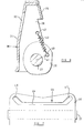
- FIGURE 4 is a cross sectional view (taken on the line IV-IV of Figure 5) of a second embodiment of the invention,
- FIGURE 5 is a front elevational view of the second embodiment of the invention,
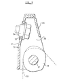
- FIGURE 6 is a sectional view, taken towards one side, of a third embodiment of the invention,
- FIGURE 7 is a view illustrating the roller of the third embodiment of the invention, and
- FIGURE 8 is a central sectional view through the embodiment shown in Figure 6 and 7.
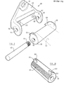
- FIGURE 9 is an exploded perspective view of another embodiment of the invention,
- FIGURE 10 is a view of the roller of the embodiment of Figure 9,
- FIGURE I I is a elevational view, partly in section, taken on the line XI-XI of Figure 12, and
- FIGURE 12. is a sectional view taken on the lines XII-XII of Figure 11.
- Referring initially to Figure I a cylindrical roller I is provided which is mounted for rotation about an
axis 2 which is offset from thecentre 3 of the cylindrical roller. The cylindrical roller I has a radius R, and a distance between the centre of theroller 3 and the axis ofrotation 2 is r. - A seat belt 4 has part thereof wrapped around the roller I, and the roller is mounted for rotation about the
axis 2 in an appropriate support element. Onlypart 5 of the support element is shown, this part comprising a vertical surface located adjacent the roller. A considerable force F has been applied to the seat belt 4 causing the roller to rotate from an initial position about theaxis 2 so that part of the periphery of the roller I is firmly clamping with the seat belt 4 against thevertical surface 5. - When in this condition the seat belt is wrapped around a predetermined portion of the periphery of the roller I indicated by the angle alpha. Also, when in this position, the angle between a vertical line extending upwardly from the
centre 3 of the roller and a line passing through thecentre 3 of the roller and thepivotal axis 2 thereof is beta. - Figures 2 and 3 plot the friction retaining the belt (when the assembly is in the clamped condition) against the ratio of r to R for different values of the angle alpha. In each case each graphical figure contains two lines relating to different values of the angle beta.
- It can be seen that the friction provided is greater when the ratio r:R approaches unity, that is to say when the axis of rotation is located very close to the periphery of the roller, and also it can be seen that the friction is greatest when the angle beta is of the smaller value.
- Turning now to Figures 4 and 5 one embodiment of the invention is illustrated. In this embodiment a
support member 10 is provided. The support member has a substantially flat base portion I provided with a through goingaperture 12 to accommodate a bolt or the like to enable thesupport member 10 to be bolted in position, for example on the 'B" post of a motor vehicle. The flat portion I I is provided with a rearwardly extendingdepression 13 and a lower rearwardly extendinglip 14 to assist in locating thesupport member 10 in an appropriate position. - The
support member 10 has two forwardly extendingside walls - A
roller 17 is mounted in position between the side walls on anaxle 18 which passes through coaligned apertures formed in theside wall support member 10. Aseat belt 19 can be passed up between the planar portion I I of thesupport member 10, and over theroller 17. It will be appreciated that when a force F is applied to the seat belt in the direction of the arrow present in Figure 4, if the force exceeds a predetermined force the roller will rotate, and the eccentric nature of the roller is such that part of the roller will then trap or clamp part of theseat belt 19 firmly against the planar portion I of thesupport member 10. - To prevent the seat belt being dragged to one side of the roller and bunching the seat belt passes through a guide provided on the roller. In this embodiment the guide is constituted by a
guide element 20 formed of a length of wire, the free ends 21, 22 of the wire being embedded in the roller. The wire is bent or otherwise configured to define aslot 23 which has alinear portion 24 extending substantially parallel with the axis of rotation of theroller 17 and a terminal upwardly extendingportion 25 which extends angularly and radially away from the axis of rotation of theroller 17. The seat belt is illustrated passing through theslot 24, and the provision of a guide of this type minimises any bunching of the seat belt. - Figures 6 to 8 illustrate another embodiment of the invention. In this embodiment of the invention a
support member 30 is provided which has a generally planarrear wall 31 defining onaperture 32 which, as shown in Figure 8, can receive agromet 33 which forms a seat for abolt 34 which can mount thesupport member 30 in position, for example on the "B" post of a motor vehicle. - A
cover member 35 is releasably connected to the base member. The base member has forwardly extendingside walls 36 which rotatably support, about anaxle 37, aneccentric roller 38. As in the previously described embodiment aseat belt 39 may pass upwardly between the roller and a part of the support member, so that when a force is applied thereto the roller will rotate and will clamp theseat belt 39 against the support member. - As shown in Figure 6 the
roller 38 is provided with arod 40 passing therethrough. Therod 40 is parallel with the axis of rotation of theroller 38, but is spaced therefrom. A notional line 41 connects the axis of therod 40 and the axis of rotation of theroller 38.Respective springs 42 are connected to the ends of the rod and are also connected to apertures 43 formed in theside walls 36 of the support member. - It is to be observed that the spring is a linear extension spring and thus applies a substantially linear force to the
rod 40. This force is applied at an angle of approximately 90o to the notional line 41. When a seat belt is wrapped around theroller 38 and a significant force is applied to the seat belt, the seat belt will overcome the biassing force provided by thespring 42, and theroller 38 will then begin to rotate in a clockwise direction as seen in Figure 6. As the roller rotates in a clockwise direction the angle between thespring 42 and the line 41 will reduce and thus the effective moment provided by the spring will also reduce. Thus, once the initial biassing force has been overcome the roller will rotate more freely. - As can been seen in Figure 7 the
roller 38 is provided with apassage 44 that is formed within the roller. The passage is thus in the form of a tunnel that extends through the roller. The passage has a centrallinear portion 45 which extends substantially parallel with the axis of rotation of the roller, and two upwardly extendingterminal portions roller 38. - Referring now to Figure 9, a further embodiment of the invention incorporates a generally
cylindrical roller 50 which, as can be seen most clearly from Figure 12, does not have a circular cross section but instead has a substantially oval cross section. Aseat belt 51 may have part thereof wrapped around theroller 50. The roller is mounted for rotation by means of atubular axle 52 which passes through anaxial bore 53 formed in the roller, the ends of theaxle 52 being received inapertures lugs support element 58 which incorporates a substantiallytriangular plate 59 provided with anaperture 60 adapted to receive a bolt to enable thesupport element 58 to be mounted on the 'B" post of a motor vehicle. - As can be seen most clearly in Figures 9 and 11 a
helical torsion spring 61 is provided which surrounds part of theaxle 52, and which engages the protrudinglug 57 and also engages theroller 50. The spring serves to retain theroller 50 in the relative rotational position illustrated in Figures 9 andI 2. - It will be observed that the
roller 50 is provided, at opposed ends thereof, with two radially projectinglugs abutments triangular plate 59 defines recesses which are dimensioned and located to receive the projectinglugs radial abutments support plate 59, thus serving to prevent further rotation of theroller 50 under the bias imparted thereto by thespring 61. - It can be seen that a part of the
roller 50 that is uppermost when the roller is in the initial position of Figures 9 and 12, that is to say the part of the roller identified by thereference numeral 68 is relatively smooth, whereas part of the roller, identified by thereference numeral 69, located adjacent theprojections - The
seat belt 39 is threaded through thepassage 44 and is thus guided by the passage. The configuration of the passage prevents any 'bunching of the seat belt within the described assembly. - In use of the roller shown in Figures 9 to 12 initially the
roller 50 is in the position illustrated in Figure 12, and the seat belt thus passes over the smooth upper part of the roller. When only a low force is applied to the seat belt, the seat belt will thus slide over this smooth portion of the roller. However, if a significant force is applied to the seat belt, the roller will rotate, in a clockwise direction as shown in Figure 12, and theknurled portion 69 of the roller will then engage the seat belt, the knurled portion of theroller 69 pressing the seat belt against the flat part of thesupport element 58 between therecesses knurled part 69 of theroller 50 grips the seat belt firmly to prevent any further amount of seat belt being paid out. - It is preferred that only the roller should be knurled since if the support is also knurled it is possible for the seat belt to be damaged.
- Whilst various embodiments of the invention have been described, it is to be understood that the description is given merely by way of example and many modifications may be made without departing from the scope of the invention.
Claims (10)
Applications Claiming Priority (2)
| Application Number | Priority Date | Filing Date | Title |
|---|---|---|---|
| GB848430469A GB8430469D0 (en) | 1984-12-03 | 1984-12-03 | Seat belt guide assembly |
| GB8430469 | 1984-12-03 |
Publications (2)
| Publication Number | Publication Date |
|---|---|
| EP0184172A2 true EP0184172A2 (en) | 1986-06-11 |
| EP0184172A3 EP0184172A3 (en) | 1987-05-27 |
Family
ID=10570614
Family Applications (1)
| Application Number | Title | Priority Date | Filing Date |
|---|---|---|---|
| EP85115251A Withdrawn EP0184172A3 (en) | 1984-12-03 | 1985-12-02 | A seat belt guide assembly |
Country Status (2)
| Country | Link |
|---|---|
| EP (1) | EP0184172A3 (en) |
| GB (1) | GB8430469D0 (en) |
Cited By (10)
| Publication number | Priority date | Publication date | Assignee | Title |
|---|---|---|---|---|
| FR2627731A1 (en) * | 1988-02-29 | 1989-09-01 | Mottin Nicole | Device to control seat-belt tension - with length between anchorage point and upper end of belt able to be increased manually by occupant |
| GB2247393A (en) * | 1990-09-03 | 1992-03-04 | Autoliv Dev | Improvements in or relating to a belt deflector |
| EP0842830A1 (en) * | 1996-11-18 | 1998-05-20 | TAKATA (EUROPE) VEHICLE SAFETY TECHNOLOGY GmbH | Seat belt guide fitting. |
| EP1754638A1 (en) * | 2005-08-19 | 2007-02-21 | Takata Corporation | Seat-belt guide anchor and seat belt apparatus having the same |
| EP1616747A3 (en) * | 2004-07-12 | 2008-12-03 | ARTSANA S.p.A. | Vehicle safety belt clamp for association with a child seat |
| US7984947B2 (en) * | 2005-11-30 | 2011-07-26 | Cybex Industrial Ltd. | Rotatable child seat for motor vehicles |
| JP2014019294A (en) * | 2012-07-18 | 2014-02-03 | Takata Corp | Tang and seat belt device using same |
| JP2014513011A (en) * | 2011-05-09 | 2014-05-29 | ティーケー ホールディングス インク. | Crew restraint system |
| EP3431348A1 (en) * | 2017-07-18 | 2019-01-23 | Volvo Car Corporation | Seat-belt guide |
| US10793102B2 (en) | 2018-10-12 | 2020-10-06 | Ford Global Technologies, Llc | Seat belt webbing guide |
Family Cites Families (4)
| Publication number | Priority date | Publication date | Assignee | Title |
|---|---|---|---|---|
| US3222107A (en) * | 1962-10-16 | 1965-12-07 | Gen Motors Corp | Retractable seat belt assembly |
| SE7906282L (en) * | 1979-07-23 | 1981-02-23 | Lindblad Stig Martin | DEVICE AT THE SEAT BELT |
| DE3032169A1 (en) * | 1980-08-26 | 1982-03-25 | Repa Feinstanzwerk Gmbh, 7071 Alfdorf | BELT TAPE CLAMPING FOR SAFETY BELTS IN MOTOR VEHICLES |
| GB8424853D0 (en) * | 1984-10-02 | 1984-11-07 | Britax Wingard Ltd | Clamping means for strap |
-
1984
- 1984-12-03 GB GB848430469A patent/GB8430469D0/en active Pending
-
1985
- 1985-12-02 EP EP85115251A patent/EP0184172A3/en not_active Withdrawn
Cited By (12)
| Publication number | Priority date | Publication date | Assignee | Title |
|---|---|---|---|---|
| FR2627731A1 (en) * | 1988-02-29 | 1989-09-01 | Mottin Nicole | Device to control seat-belt tension - with length between anchorage point and upper end of belt able to be increased manually by occupant |
| GB2247393A (en) * | 1990-09-03 | 1992-03-04 | Autoliv Dev | Improvements in or relating to a belt deflector |
| GB2247393B (en) * | 1990-09-03 | 1994-07-06 | Autoliv Dev | Improvements in or relating to a belt deflector |
| EP0842830A1 (en) * | 1996-11-18 | 1998-05-20 | TAKATA (EUROPE) VEHICLE SAFETY TECHNOLOGY GmbH | Seat belt guide fitting. |
| EP1616747A3 (en) * | 2004-07-12 | 2008-12-03 | ARTSANA S.p.A. | Vehicle safety belt clamp for association with a child seat |
| EP1754638A1 (en) * | 2005-08-19 | 2007-02-21 | Takata Corporation | Seat-belt guide anchor and seat belt apparatus having the same |
| US7984947B2 (en) * | 2005-11-30 | 2011-07-26 | Cybex Industrial Ltd. | Rotatable child seat for motor vehicles |
| JP2014513011A (en) * | 2011-05-09 | 2014-05-29 | ティーケー ホールディングス インク. | Crew restraint system |
| JP2014019294A (en) * | 2012-07-18 | 2014-02-03 | Takata Corp | Tang and seat belt device using same |
| US9615632B2 (en) | 2012-07-18 | 2017-04-11 | Takata Corporation | Tongue and seat belt device using same |
| EP3431348A1 (en) * | 2017-07-18 | 2019-01-23 | Volvo Car Corporation | Seat-belt guide |
| US10793102B2 (en) | 2018-10-12 | 2020-10-06 | Ford Global Technologies, Llc | Seat belt webbing guide |
Also Published As
| Publication number | Publication date |
|---|---|
| EP0184172A3 (en) | 1987-05-27 |
| GB8430469D0 (en) | 1985-01-09 |
Similar Documents
| Publication | Publication Date | Title |
|---|---|---|
| DE69832680T2 (en) | Tilt sensor controlled seat belt retractor | |
| US5037135A (en) | Limited rotation webbing guide | |
| US4494774A (en) | Belt band-clamping arrangement for safety belts in motor vehicles | |
| DE3412383A1 (en) | DEFLECTION DEVICE FOR A SAFETY BELT WITH STAGE BELT CLAMPING | |
| DE29621717U1 (en) | Cable winder for the cable of a hands-free set | |
| DE2432956C3 (en) | Belt take-up clamp machine | |
| EP0382870B1 (en) | Seat belt retractor | |
| DE4031143C2 (en) | Seat belt retractor with strain relief | |
| DE3008299C2 (en) | Automatic retractor for a seat belt | |
| DE10204090C1 (en) | Safety belt lock and fastening system for road vehicle is mounted on arm on pivot with fastening screw and flat coil spring | |
| DE2256184C2 (en) | Retractor for seat belts in vehicles | |
| DE3001091A1 (en) | ENERGY ABSORBER FOR LOAD-BEARING FLEXIBLE TENSIONERS | |
| DE3009701A1 (en) | REELING MACHINE FOR A BELT | |
| WO1996022201A1 (en) | Transport safety system on a belt winding unit | |
| DE2047706A1 (en) | Seat belts for vehicle occupants | |
| DE3220476A1 (en) | FASTENING DEVICE FOR TWO WHEELS | |
| DE3627715C2 (en) | ||
| DE4423958A1 (en) | Belt retractor | |
| DE1810333A1 (en) | Vehicle seat | |
| DE69112363T2 (en) | REEL FOR A SEAT BELT. | |
| DE102006037544A1 (en) | Belt roller with vehicle-sensitive blocking system, includes ganged control lever coupled via friction coupling to belt coil | |
| DE3116705A1 (en) | SELF-LOCKING BELT REEL FOR SAFETY BELTS | |
| DE102004036778B4 (en) | Energy absorption device for a vehicle steering column | |
| DE2728155A1 (en) | Blocking mechanism actuating seat belt spool shaft - has resilient circular segment which can dislocate spool shaft from centre | |
| DE3033745C2 (en) | Automatic retractor for a seat belt |
Legal Events
| Date | Code | Title | Description |
|---|---|---|---|
| PUAI | Public reference made under article 153(3) epc to a published international application that has entered the european phase |
Free format text: ORIGINAL CODE: 0009012 |
|
| AK | Designated contracting states |
Kind code of ref document: A2 Designated state(s): DE FR GB |
|
| PUAL | Search report despatched |
Free format text: ORIGINAL CODE: 0009013 |
|
| AK | Designated contracting states |
Kind code of ref document: A3 Designated state(s): DE FR GB |
|
| 17P | Request for examination filed |
Effective date: 19870914 |
|
| 17Q | First examination report despatched |
Effective date: 19880928 |
|
| STAA | Information on the status of an ep patent application or granted ep patent |
Free format text: STATUS: THE APPLICATION IS DEEMED TO BE WITHDRAWN |
|
| 18D | Application deemed to be withdrawn |
Effective date: 19890208 |
|
| RIN1 | Information on inventor provided before grant (corrected) |
Inventor name: ANDERSSON, STURE ROLAND |