EP0183534A1 - Skeletal tissue stimulator and a low voltage oscillator circuit for use therein - Google Patents
Skeletal tissue stimulator and a low voltage oscillator circuit for use therein Download PDFInfo
- Publication number
- EP0183534A1 EP0183534A1 EP85308611A EP85308611A EP0183534A1 EP 0183534 A1 EP0183534 A1 EP 0183534A1 EP 85308611 A EP85308611 A EP 85308611A EP 85308611 A EP85308611 A EP 85308611A EP 0183534 A1 EP0183534 A1 EP 0183534A1
- Authority
- EP
- European Patent Office
- Prior art keywords
- battery
- load
- state
- skeletal tissue
- coupled
- Prior art date
- Legal status (The legal status is an assumption and is not a legal conclusion. Google has not performed a legal analysis and makes no representation as to the accuracy of the status listed.)
- Granted
Links
Images


Classifications
-
- A—HUMAN NECESSITIES
- A61—MEDICAL OR VETERINARY SCIENCE; HYGIENE
- A61N—ELECTROTHERAPY; MAGNETOTHERAPY; RADIATION THERAPY; ULTRASOUND THERAPY
- A61N1/00—Electrotherapy; Circuits therefor
- A61N1/18—Applying electric currents by contact electrodes
- A61N1/32—Applying electric currents by contact electrodes alternating or intermittent currents
- A61N1/326—Applying electric currents by contact electrodes alternating or intermittent currents for promoting growth of cells, e.g. bone cells
-
- A—HUMAN NECESSITIES
- A61—MEDICAL OR VETERINARY SCIENCE; HYGIENE
- A61F—FILTERS IMPLANTABLE INTO BLOOD VESSELS; PROSTHESES; DEVICES PROVIDING PATENCY TO, OR PREVENTING COLLAPSING OF, TUBULAR STRUCTURES OF THE BODY, e.g. STENTS; ORTHOPAEDIC, NURSING OR CONTRACEPTIVE DEVICES; FOMENTATION; TREATMENT OR PROTECTION OF EYES OR EARS; BANDAGES, DRESSINGS OR ABSORBENT PADS; FIRST-AID KITS
- A61F2/00—Filters implantable into blood vessels; Prostheses, i.e. artificial substitutes or replacements for parts of the body; Appliances for connecting them with the body; Devices providing patency to, or preventing collapsing of, tubular structures of the body, e.g. stents
- A61F2/02—Prostheses implantable into the body
- A61F2/28—Bones
- A61F2002/2821—Bone stimulation by electromagnetic fields or electric current for enhancing ossification
Definitions
- the present invention relates to skeletal tissue stimulators, more particularly bone growth stimulators and still more particularly to low voltage oscillator circuits for use in such stimulators.
- a pair of electrodes are invasively inserted near the fracture site. These electrodes are then connected to an electrical circuit which passes electrical current between the electrodes and, hence, to the bone tissue. The electrical circuit determines the amount of and the characteristics of the electrical current which is passed to the electrodes and which is then utilized to stimulate the skeletal tissue.
- a variety of electrical current wave forms have been used for skeletal tissue, especially bone, stimulation.
- electrical currents involving direct current wave forms and alternating current wave forms have been used.
- Alternating current wave forms with differing amplitudes, frequencies, duty cycles and average DC levels have been utilized.
- One example of an electrical current which has been found to be useful in skeletal tissue stimulators is an electrical pulsed current wave form of approximately 20 microamperes with approximately 50% duty cycle.
- an approximate DC current is applied for approximately one half of the time and a low electrical current is applied for remaining approximately one half time.
- Such an electrical current wave form then resembles an approximate square wave with a DC shift of approximately one half of the peak-to-peak value.
- the device since the device is implanted or otherwise located near the site of stimulation, there is a need to have a compact unit.
- the compactness of the stimulation device necessarily limits its size and, hence, the capacity of its energy source, i.e. battery.
- the circuit since the effectiveness of the stimulation is, to a certain extent, the result of the magnitude of the electrical current induced into the skeletal tissue, the circuit must be capable of supplying and maintaining an electrical current at that level. This requirement militates toward a larger energy source, i.e. battery.
- the device is invasive, i.e. implanted near the skeletal tissue to be stimulated, it is desirable to extend the lifetime of the energy source, i.e. battery, in order to achieve a maximum amount of stimulation with a minimum amount of use of invasive procedures.
- the present invention provides an implantable low voltage oscillator circuit which is capable of being coupled to a portion of the body which acts as a load to the circuit.
- the circuit has a battery with a first terminal and a second terminal.
- the circuit also has an oscillator having a first state and a second state and being operatively coupled to the first terminal of the battery.
- the circuit also has a capacitive storage means operatively coupled between the oscillator and the second terminal of the battery for controlling the oscillation of the oscillator.
- the circuit also has a charging device operatively coupled to trrib capacitive storage means for charging the capacitive storage means when the oscillator is in the first state.
- the circuit also has a discharge device operatively coupled between the capacitive storage means and the load for discharging the capacitive storage means through the load when the oscillator is in the second state.
- the capacitive storage means and the load are the only current paths to or from the second terminal of the battery.
- the present invention also provides a skeletal tissue stimulator capable of being coupled to the skeletal tissue, e.g. bone, which acts as a load for the stimulator.
- a battery is utilized which has a first terminal and a second terminal. The second terminal of the battery is capable of being coupled to the skeletal tissue at a first location.
- a latch is operatively coupled to the first terminal of the battery and is capable of being coupled to the skeletal tissue at a second location.
- the latch has a first state and a second state. The latch allows electrical current to flow between the battery and the skeletal tissue when the latch is in the first state but does not allow electrical current to flow between the battery and the skeletal tissue when the latch is in the second state.
- a capacitor is operatively coupled between the latch and the second terminal of the battery.
- the capacitor controls the latch to the first state when the capacitor is substantially discharged and controls the latched to the second state when the capacitor is substantially charged.
- a charger is operatiavely coupled to the battery and the capacitor for charging the capacitor from the battery when the latch is in the first state.
- a discharger is operatively coupled to the capacitor and is capable of being coupled to the skeletal tissue and allows the capacitor to discharge through the skeletal tissue when the latch is in the second state.
- the present invention also provides a skeletal tissue stimulator, e.g. a bone growth stimulator, which is adapted to be coupled to a, load, a portion of which is adapted to be the skeletal tissue in a body whose growth is to be stimulated.
- the skeletal tissue stimulator has a battery and an oscillator circuit coupled to the battery and adapted to be coupled to the load.
- An oscillator circuit has a first state in which current is allowed to flow between the battery and the load and a second state in which current is not allowed to flow between the battery and the load.
- the oscillator circuit has a storage element adapted to be ranged in parallel with the load, the storage element being charged from the battery and being adapted to be discharged through the load.
- the stimulator is characterized in that all current provided by the battery must flow through either the storage element or the load.
- a skeletal tissue stimulation device or a low voltage oscillator for use in such a device characterized in this manner achieves several notable, significant advantages.
- the circuit operates from a low voltage energy source, i.e. a battery, which can be implanted near the stimulation site.
- the circuit draws no, or very little electrical current from the energy source when there is no load (no tissue to be stimulated). This is significant so that a long shelf life can be achieved before the stimulation device is implanted and, hence, ready for stimulation.
- the circuit provides a relatively stable electrical current output under a wide variety of load impedances. This result is significant because the impedance of the load, that is the impedance of the skeletal tissue which is to be stimulated, varies significantly from individual to individual and from implantation site to implantation site. Further, the circuit provides safe levels of electrical current under all possible load conditions.
- FIG. 1 discloses a skeletal tissue stimulator, e.g. a bone growth stimulator, 10 of the present invention.
- Skeletal tissue stimulator 10 contains circuit 12 contained within housing 14 secured with an appropriate potting material 16, such as Hysol epoxy. Output leads 18 and 20 from circuit 12 extend beyond housing 14. Skeletal tissue stimulator 10 may then be implanted into the body near the skeletal tissue, e.g. bone, which is to be stimulated. The skeletal tissue which is to be stimulated is located generally between output leads 18 and 20 which skeletal tissue forms the electrical load for circuit 12.
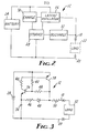
- FIG. 2 is a block diagram of the circuit 12 of the present invention.
- circuit 12 has output leads 18 and 2 to which the skeletal tissue or load 22 may be connected.
- Circuit 12 consists of an energy source or a battery 24 which is coupled to an oscillator circuit 26.
- Oscillator circuit 26 is coupled to output lead 18 and to storage device 28.
- When oscillator circuit 26 is in one state current from battery 24 may flow through oscillator 26 and subsequently load 22 by way of output leads 18 and 20 to provide a stimulating electric current to load 22.
- oscillator 26 is in another state, very little or no electric current is allowed to flow through oscillator circuit 26 and, hence, through output leads 18 and 20 to load 22.
- Charging device 30 is coupled between battery 24 and storage device 28 for supplying charge to storage device 20 from battery 24 when storage device 28 is substantially discharged.
- Storage device 28 is coupled back to oscillator circuit 26, either through charging device 30 as shown in Figure 2 or directly, in order for storage device 28 to change the state of oscillator circuit 26 depending upon the energy storage or charge state of storage device 28.
- Discharge device 32 is coupled between storage device 28 and output lead 18. Discharge device 32 provides a discharge path for storage device 28 through output leads 18 and 20 and, hence, through load 22.
- an operation circuit 12 allows essentially all of the energy, i.e. electric current, from battery 24 to flow through load 22 and, hence, be useful in providing skeletal tissue stimulation. This results in an effective and efficient use of energy source or battery 24 and, hence, the longevity of circuit 12 when implanted and utilized.
- storage device 28 must discharge through load 22 by way of discharge device 32. Thus, if load 22 is disconnected there is no path to discharge storage device 28 and, hence, there is no current flow to discharge battery 24.
- storage device 28 may not be a perfect storage device and, hence, may have a minute leakage current which for purposes of the present embodiment is negligible and can be ignored.
- circuit 12 A more detailed understanding of the operation of circuit 12 may be had by reference to the detailed circuit diagram of a preferred embodiment of the present invention as illustrated in Figure 3.
- load 22 is coupled to circuit 12 with output leads 18 and 20.
- Circuit 12 also contains a battery 24.
- Storage device 28 is represented by capacitor 34.
- Transistors 36 and 38 along with resistors 40, 42 and 44 form oscillator circuit 26 and charging device 30.
- Resistor 46 and diode 48 form discharge device 32.
- Resistor 50 is coupled between diode 48 and transistor 38 and output lead 18.
- the circuit of the present invention and, hence, the skeletal tissue stimulator of the present invention involve several distinguished, advantageous characteristics.
- capacitor 34 cannot discharge and, hence, battery 24 cannot be drained. This will enhance and prolong the shelf life of the skeletal tissue stimulator prior to its implantation and use as a skeletal tissue stimulator.
- all of the electrical current involved in charging capacitor 34 subsequently passes through load 22 when capacitor 34 discharges. This results in the efficient use of the energy stored in battery 24 and results in essentially all of the electric current from battery 24 resulting in skeletal tissue stimulation through load 22.
- resistor 50 half of the voltage from the output of the circuit 12 will be dropped across resistor 50 since resistor 50 is approximately equal the expected resistive component of load 22. However, the loss of half of the voltage is appropriate since it is much more important in a skeletal tissue stimulator to maintain the proper electric current level.
- the use of resistor 50 stabilizes the output electric current over a wider range of resistive loads.
- Figure 5 represents an alternative skeletal tissue stimulator utilizing an electric circuit 12 in which the output current from the circuit 12 could drive two loads 60 and 62.
- one skeletal tissue stimulator circuit 12 could drive two pairs of electrodes and stimulate skeletal tissue in two different locations.
- the loads 60 and 62 are essentially coupled in parallel with each other at the output of transistor 38.
- Buffering resistance 50 as in Figure 3 may be split into resistances 64 and 66 as illustrated in Figure 5 or they may be combined in one resistance and the loads split following the passage through this resistance.
Abstract
Description
- The present invention relates to skeletal tissue stimulators, more particularly bone growth stimulators and still more particularly to low voltage oscillator circuits for use in such stimulators.
- It is known that, in certain circumstances, the application of an electrical current to skeletal tissue, especially bone tissue, may promote growth of that skeletal tissue. This is particularly useful in situations of non-union or delayed union of fractures of bones.
- In one type of a typical skeletal tissue stimulator, a pair of electrodes are invasively inserted near the fracture site. These electrodes are then connected to an electrical circuit which passes electrical current between the electrodes and, hence, to the bone tissue. The electrical circuit determines the amount of and the characteristics of the electrical current which is passed to the electrodes and which is then utilized to stimulate the skeletal tissue.
- A variety of electrical current wave forms have been used for skeletal tissue, especially bone, stimulation. In the past, electrical currents involving direct current wave forms and alternating current wave forms have been used. Alternating current wave forms with differing amplitudes, frequencies, duty cycles and average DC levels have been utilized. One example of an electrical current which has been found to be useful in skeletal tissue stimulators is an electrical pulsed current wave form of approximately 20 microamperes with approximately 50% duty cycle. In this electrical current wave form, an approximate DC current is applied for approximately one half of the time and a low electrical current is applied for remaining approximately one half time. Such an electrical current wave form then resembles an approximate square wave with a DC shift of approximately one half of the peak-to-peak value.
- In certain skeletal tissue, e.g. bone, stimulators, it is desired to implant the entire stimulation unit in order to avoid a percutaneous connection between the electrodes and the stimulation unit. In this situation, several countervailing practical constraints tend to limit the usefulness of the stimulation device.
- First, since the device is implanted or otherwise located near the site of stimulation, there is a need to have a compact unit. The compactness of the stimulation device necessarily limits its size and, hence, the capacity of its energy source, i.e. battery.
- Second, since the effectiveness of the stimulation is, to a certain extent, the result of the magnitude of the electrical current induced into the skeletal tissue, the circuit must be capable of supplying and maintaining an electrical current at that level. This requirement militates toward a larger energy source, i.e. battery.
- Third, since the device is invasive, i.e. implanted near the skeletal tissue to be stimulated, it is desirable to extend the lifetime of the energy source, i.e. battery, in order to achieve a maximum amount of stimulation with a minimum amount of use of invasive procedures.
- The present invention provides an implantable low voltage oscillator circuit which is capable of being coupled to a portion of the body which acts as a load to the circuit. The circuit has a battery with a first terminal and a second terminal. The circuit also has an oscillator having a first state and a second state and being operatively coupled to the first terminal of the battery. The circuit also has a capacitive storage means operatively coupled between the oscillator and the second terminal of the battery for controlling the oscillation of the oscillator. The circuit also has a charging device operatively coupled to trrib capacitive storage means for charging the capacitive storage means when the oscillator is in the first state. The circuit also has a discharge device operatively coupled between the capacitive storage means and the load for discharging the capacitive storage means through the load when the oscillator is in the second state. The capacitive storage means and the load are the only current paths to or from the second terminal of the battery.
- The present invention also provides a skeletal tissue stimulator capable of being coupled to the skeletal tissue, e.g. bone, which acts as a load for the stimulator. A battery is utilized which has a first terminal and a second terminal. The second terminal of the battery is capable of being coupled to the skeletal tissue at a first location. A latch is operatively coupled to the first terminal of the battery and is capable of being coupled to the skeletal tissue at a second location. The latch has a first state and a second state. The latch allows electrical current to flow between the battery and the skeletal tissue when the latch is in the first state but does not allow electrical current to flow between the battery and the skeletal tissue when the latch is in the second state. A capacitor is operatively coupled between the latch and the second terminal of the battery. The capacitor controls the latch to the first state when the capacitor is substantially discharged and controls the latched to the second state when the capacitor is substantially charged. A charger is operatiavely coupled to the battery and the capacitor for charging the capacitor from the battery when the latch is in the first state. A discharger is operatively coupled to the capacitor and is capable of being coupled to the skeletal tissue and allows the capacitor to discharge through the skeletal tissue when the latch is in the second state.
- The present invention also provides a skeletal tissue stimulator, e.g. a bone growth stimulator, which is adapted to be coupled to a, load, a portion of which is adapted to be the skeletal tissue in a body whose growth is to be stimulated. The skeletal tissue stimulator has a battery and an oscillator circuit coupled to the battery and adapted to be coupled to the load. An oscillator circuit has a first state in which current is allowed to flow between the battery and the load and a second state in which current is not allowed to flow between the battery and the load. The oscillator circuit has a storage element adapted to be ranged in parallel with the load, the storage element being charged from the battery and being adapted to be discharged through the load. The stimulator is characterized in that all current provided by the battery must flow through either the storage element or the load.
- A skeletal tissue stimulation device or a low voltage oscillator for use in such a device characterized in this manner achieves several notable, significant advantages. First, the circuit operates from a low voltage energy source, i.e. a battery, which can be implanted near the stimulation site. Second, the circuit draws no, or very little electrical current from the energy source when there is no load (no tissue to be stimulated). This is significant so that a long shelf life can be achieved before the stimulation device is implanted and, hence, ready for stimulation. Third, while the circuit is in operation, all of the electrical current from the battery reaches the load, i.e., the skeletal tissue which is to be stimulated. This is because all of the current from the energy source either is allowed to flow directly to the skeletal tissue or to charge the capacitor, or capacitive storage means, which subsequently is discharged through the skeletal tissue. No other current, save for the leakage current of the capacitive device, flows from the battery or energy source. Fourth, the circuit provides a relatively stable electrical current output under a wide variety of load impedances. This result is significant because the impedance of the load, that is the impedance of the skeletal tissue which is to be stimulated, varies significantly from individual to individual and from implantation site to implantation site. Further, the circuit provides safe levels of electrical current under all possible load conditions.
- The foregoing advantages, construction and operation of the present invention will become more readily apparent from the following description and accompanying drawings in which:
- Figure 1 is a diagram of a skeletal tissue stimulator of the present invention.
- Figure 2 is a block diagram of the circuit of the present invention;
- Figure 3 is a detailed circuit diagram of a preferred embodiment of the present invention;
- Figure 4 is an electrical voltage wave form of the output of the circuit of the present invention taken across the load; and
- Figure 5 is a detailed circuit diagram of an alternative embodiment of the present invention.
- Figure 1 discloses a skeletal tissue stimulator, e.g. a bone growth stimulator, 10 of the present invention.
Skeletal tissue stimulator 10 containscircuit 12 contained within housing 14 secured with anappropriate potting material 16, such as Hysol epoxy. Output leads 18 and 20 fromcircuit 12 extend beyond housing 14.Skeletal tissue stimulator 10 may then be implanted into the body near the skeletal tissue, e.g. bone, which is to be stimulated. The skeletal tissue which is to be stimulated is located generally between output leads 18 and 20 which skeletal tissue forms the electrical load forcircuit 12. - Figure 2 is a block diagram of the
circuit 12 of the present invention. As in Figure 1,circuit 12 has output leads 18 and 2 to which the skeletal tissue or load 22 may be connected.Circuit 12 consists of an energy source or abattery 24 which is coupled to anoscillator circuit 26.Oscillator circuit 26 is coupled tooutput lead 18 and tostorage device 28. Whenoscillator circuit 26 is in one state, current frombattery 24 may flow throughoscillator 26 and subsequently load 22 by way of output leads 18 and 20 to provide a stimulating electric current to load 22. Whenoscillator 26 is in another state, very little or no electric current is allowed to flow throughoscillator circuit 26 and, hence, through output leads 18 and 20 to load 22. Chargingdevice 30 is coupled betweenbattery 24 andstorage device 28 for supplying charge tostorage device 20 frombattery 24 whenstorage device 28 is substantially discharged.Storage device 28 is coupled back tooscillator circuit 26, either through chargingdevice 30 as shown in Figure 2 or directly, in order forstorage device 28 to change the state ofoscillator circuit 26 depending upon the energy storage or charge state ofstorage device 28.Discharge device 32 is coupled betweenstorage device 28 andoutput lead 18.Discharge device 32 provides a discharge path forstorage device 28 through output leads 18 and 20 and, hence, throughload 22. - Note in Figure 2 that there are only 2 paths for electric current to flow to or from
battery 24, i.e. throughstorage device 28 and throughload 22. Also note that any energy stored instorage device 28 must be discharged throughdischarge device 32 throughload 22. This arrangement provides a couple of unique advantages. First, anoperation circuit 12 allows essentially all of the energy, i.e. electric current, frombattery 24 to flow throughload 22 and, hence, be useful in providing skeletal tissue stimulation. This results in an effective and efficient use of energy source orbattery 24 and, hence, the longevity ofcircuit 12 when implanted and utilized. Second, that whenload 22 is disconnected, i.e. when the circuit is not implanted with skeletal tissue to be stimulated, there is no path for electrical current to dischargebattery 24. As previously discussed, the only two paths for electric current are throughstorage device 28 and throughload 22. In addition, as previously discussed,storage device 28 must discharge throughload 22 by way ofdischarge device 32. Thus, ifload 22 is disconnected there is no path to dischargestorage device 28 and, hence, there is no current flow to dischargebattery 24. Of course,storage device 28 may not be a perfect storage device and, hence, may have a minute leakage current which for purposes of the present embodiment is negligible and can be ignored. - A more detailed understanding of the operation of
circuit 12 may be had by reference to the detailed circuit diagram of a preferred embodiment of the present invention as illustrated in Figure 3. As in Figure 2, load 22 is coupled tocircuit 12 with output leads 18 and 20.Circuit 12 also contains abattery 24.Storage device 28 is represented bycapacitor 34.Transistors resistors form oscillator circuit 26 and chargingdevice 30.Resistor 46 anddiode 48form discharge device 32.Resistor 50 is coupled betweendiode 48 andtransistor 38 andoutput lead 18. - Operation of the detailed circuit diagram of Figure 3 is as follows. When
capacitor 34 is in its discharged state,transistor 36 will be on which in turn will turn ontransistor 38. The collector oftransistor 38 will go high and result in current flow throughresistor 50, output leads 18 and 20 throughload 22. As this occurs, the base current throughtransistor 36 will chargecapacitor 34. Ascapacitor 34 becomes charged, the base voltage oftransistor 36 will drop which will lower the collector current throughtransistor 36. This in turn will drop the base and collector voltages oftransistor 38 and, hence, bothtransistors transistor 38 to theload 22 resulting in no voltage onload 22. Withtransistors capacitor 34 will discharge throughresistor 46,diode 48 andresistor 50 throughload 22. Ascapacitor 34 is discharged, the cycle then repeats itself. This results in thevoltage wave form 52 illustrated in Figure 4. Astransistors transistor 38 and, hence, throughresistor 50 to load 22. For the voltages and components preferred in Figure 3, this results in a 0.75 volt potential across an exemplary resistive load of 47 kilohms which is exemplary of a skeletal tissue load. Ascapacitor 34 becomes charged and, hence,transistors capacitor 34 then discharges throughload 22. This is represented atpoint 54 on the wave form in which the electric current through the load is formed by the discharge fromcapacitor 34 and results in a voltage of approximately 0.3 volts acrossresistive load 22. The wave form repeats itself at points 56 and 58 corresponding to previously describedpoints - The circuit of the present invention and, hence, the skeletal tissue stimulator of the present invention involve several distinguished, advantageous characteristics. When there is no
resistive load 22,capacitor 34 cannot discharge and, hence,battery 24 cannot be drained. This will enhance and prolong the shelf life of the skeletal tissue stimulator prior to its implantation and use as a skeletal tissue stimulator. Second, all of the electrical current involved in chargingcapacitor 34 subsequently passes throughload 22 whencapacitor 34 discharges. This results in the efficient use of the energy stored inbattery 24 and results in essentially all of the electric current frombattery 24 resulting in skeletal tissue stimulation throughload 22. With the inclusion ofresistor 50, half of the voltage from the output of thecircuit 12 will be dropped acrossresistor 50 sinceresistor 50 is approximately equal the expected resistive component ofload 22. However, the loss of half of the voltage is appropriate since it is much more important in a skeletal tissue stimulator to maintain the proper electric current level. The use ofresistor 50 stabilizes the output electric current over a wider range of resistive loads. - Figure 5 represents an alternative skeletal tissue stimulator utilizing an
electric circuit 12 in which the output current from thecircuit 12 could drive twoloads tissue stimulator circuit 12 could drive two pairs of electrodes and stimulate skeletal tissue in two different locations. Theloads transistor 38. Bufferingresistance 50 as in Figure 3 may be split intoresistances - Thus, it can be seen that there has been shown and described a novel skeletal tissue stimulator and a novel circuit for use in a skeletal tissue stimulator. It is to be recognized and understood, however, that various changes, substitutions and modifications in the details of the described invention can be made by those of skill in the art without departing from the scope of the invention as defined in the following claims.
Claims (3)
Priority Applications (1)
| Application Number | Priority Date | Filing Date | Title |
|---|---|---|---|
| AT85308611T ATE43248T1 (en) | 1984-11-28 | 1985-11-27 | SKELETON TISSUE STIMULATOR AND LOW VOLTAGE OSCILLATOR CIRCUIT USED THEREFORE. |
Applications Claiming Priority (2)
| Application Number | Priority Date | Filing Date | Title |
|---|---|---|---|
| US675725 | 1984-11-28 | ||
| US06/675,725 US4665920A (en) | 1984-11-28 | 1984-11-28 | Skeletal tissue stimulator and a low voltage oscillator circuit for use therein |
Publications (2)
| Publication Number | Publication Date |
|---|---|
| EP0183534A1 true EP0183534A1 (en) | 1986-06-04 |
| EP0183534B1 EP0183534B1 (en) | 1989-05-24 |
Family
ID=24711712
Family Applications (1)
| Application Number | Title | Priority Date | Filing Date |
|---|---|---|---|
| EP85308611A Expired EP0183534B1 (en) | 1984-11-28 | 1985-11-27 | Skeletal tissue stimulator and a low voltage oscillator circuit for use therein |
Country Status (8)
| Country | Link |
|---|---|
| US (1) | US4665920A (en) |
| EP (1) | EP0183534B1 (en) |
| JP (1) | JPH067869B2 (en) |
| AT (1) | ATE43248T1 (en) |
| AU (1) | AU584937B2 (en) |
| CA (1) | CA1268217A (en) |
| DE (1) | DE3570366D1 (en) |
| ES (1) | ES8706456A1 (en) |
Cited By (1)
| Publication number | Priority date | Publication date | Assignee | Title |
|---|---|---|---|---|
| US5099840A (en) * | 1988-01-20 | 1992-03-31 | Goble Nigel M | Diathermy unit |
Families Citing this family (32)
| Publication number | Priority date | Publication date | Assignee | Title |
|---|---|---|---|---|
| JPS63122468A (en) * | 1986-11-11 | 1988-05-26 | 林原 健 | Low frequency treatment device for bathroom |
| US5047005A (en) * | 1987-01-28 | 1991-09-10 | Cadwell Industries, Inc. | Method and apparatus for magnetically stimulating neurons |
| US5116304A (en) * | 1987-01-28 | 1992-05-26 | Cadwell Industries, Inc. | Magnetic stimulator with skullcap-shaped coil |
| US4926864A (en) * | 1987-04-24 | 1990-05-22 | Minnesota Mining And Manufacturing Company | Biological tissue stimulator with time-shared logic driving output timing and high voltage step-up circuit |
| US4917093A (en) * | 1987-06-12 | 1990-04-17 | Minnesota Mining And Manufacturing Company | Biological tissue stimulator with adjustable high voltage power supply dependent upon load impedance |
| US5038780A (en) * | 1988-04-29 | 1991-08-13 | The Biotronics Research Corp. | Method and apparatus for capacitively regenerating tissue and bone |
| US7431722B1 (en) * | 1995-02-27 | 2008-10-07 | Warsaw Orthopedic, Inc. | Apparatus including a guard member having a passage with a non-circular cross section for providing protected access to the spine |
| US6123705A (en) | 1988-06-13 | 2000-09-26 | Sdgi Holdings, Inc. | Interbody spinal fusion implants |
| US7534254B1 (en) * | 1988-06-13 | 2009-05-19 | Warsaw Orthopedic, Inc. | Threaded frusto-conical interbody spinal fusion implants |
| US6770074B2 (en) | 1988-06-13 | 2004-08-03 | Gary Karlin Michelson | Apparatus for use in inserting spinal implants |
| US5484437A (en) | 1988-06-13 | 1996-01-16 | Michelson; Gary K. | Apparatus and method of inserting spinal implants |
| US6923810B1 (en) * | 1988-06-13 | 2005-08-02 | Gary Karlin Michelson | Frusto-conical interbody spinal fusion implants |
| US7491205B1 (en) * | 1988-06-13 | 2009-02-17 | Warsaw Orthopedic, Inc. | Instrumentation for the surgical correction of human thoracic and lumbar spinal disease from the lateral aspect of the spine |
| US5015247A (en) * | 1988-06-13 | 1991-05-14 | Michelson Gary K | Threaded spinal implant |
| EP0703757B1 (en) * | 1988-06-13 | 2003-08-27 | Karlin Technology, Inc. | Apparatus for inserting spinal implants |
| US6120502A (en) * | 1988-06-13 | 2000-09-19 | Michelson; Gary Karlin | Apparatus and method for the delivery of electrical current for interbody spinal arthrodesis |
| US6210412B1 (en) | 1988-06-13 | 2001-04-03 | Gary Karlin Michelson | Method for inserting frusto-conical interbody spinal fusion implants |
| US5772661A (en) * | 1988-06-13 | 1998-06-30 | Michelson; Gary Karlin | Methods and instrumentation for the surgical correction of human thoracic and lumbar spinal disease from the antero-lateral aspect of the spine |
| US5593409A (en) | 1988-06-13 | 1997-01-14 | Sofamor Danek Group, Inc. | Interbody spinal fusion implants |
| US7452359B1 (en) | 1988-06-13 | 2008-11-18 | Warsaw Orthopedic, Inc. | Apparatus for inserting spinal implants |
| US4974114A (en) * | 1989-02-13 | 1990-11-27 | Lti Biomedical, Inc. | Energy recovery circuit for electrotherapy device |
| US5565005A (en) * | 1992-02-20 | 1996-10-15 | Amei Technologies Inc. | Implantable growth tissue stimulator and method operation |
| EP0561068B1 (en) * | 1992-02-20 | 1999-03-03 | Neomedics, Inc. | Implantable bone growth stimulator |
| EP1093760B1 (en) | 1993-06-10 | 2004-11-17 | Karlin Technology, Inc. | Spinal distractor |
| US5460593A (en) * | 1993-08-25 | 1995-10-24 | Audiodontics, Inc. | Method and apparatus for imparting low amplitude vibrations to bone and similar hard tissue |
| US5524624A (en) * | 1994-05-05 | 1996-06-11 | Amei Technologies Inc. | Apparatus and method for stimulating tissue growth with ultrasound |
| US6758849B1 (en) | 1995-02-17 | 2004-07-06 | Sdgi Holdings, Inc. | Interbody spinal fusion implants |
| US6143035A (en) * | 1999-01-28 | 2000-11-07 | Depuy Orthopaedics, Inc. | Implanted bone stimulator and prosthesis system and method of enhancing bone growth |
| US6648639B2 (en) * | 2000-09-22 | 2003-11-18 | The Board Of Trustees Of The University Of Illinois | Device and method for treatment of malocclusion utilizing cyclical forces |
| EP1765204B1 (en) | 2004-06-07 | 2018-12-26 | Synthes GmbH | Orthopaedic implant with sensors |
| WO2006084239A2 (en) * | 2005-02-04 | 2006-08-10 | Intellistem Orthopaedic Innovations, Inc. | Implanted prosthetic device |
| US8908891B2 (en) | 2011-03-09 | 2014-12-09 | Audiodontics, Llc | Hearing aid apparatus and method |
Citations (6)
| Publication number | Priority date | Publication date | Assignee | Title |
|---|---|---|---|---|
| AT193953B (en) * | 1955-06-21 | 1957-12-10 | Philips Nv | Circuit for generating a sawtooth-shaped current through an inductance |
| US3518996A (en) * | 1967-04-17 | 1970-07-07 | Eloy Cortina | Muscle stimulator |
| US3650275A (en) * | 1968-08-13 | 1972-03-21 | Bio Controls Corp | Method and apparatus for controlling anal incontinence |
| DE2318576A1 (en) * | 1972-04-12 | 1973-10-18 | Nat Patent Dev Corp | DEVICE FOR INFLUENCING BONE GROWTH |
| GB1392876A (en) * | 1971-06-09 | 1975-05-07 | Dassault Electronique | Method and device for generating electrical oscillations |
| GB1419660A (en) * | 1972-01-28 | 1975-12-31 | Esb Inc | Electrical medical devices |
Family Cites Families (8)
| Publication number | Priority date | Publication date | Assignee | Title |
|---|---|---|---|---|
| US3311111A (en) * | 1964-08-11 | 1967-03-28 | Gen Electric | Controllable electric body tissue stimulators |
| US3348167A (en) * | 1966-04-20 | 1967-10-17 | Avco Corp | Relaxation oscillator requiring low current |
| US3508167A (en) * | 1968-06-28 | 1970-04-21 | Mennen Greatbatch Electronics | Pulse generator |
| US3807411A (en) * | 1971-08-16 | 1974-04-30 | Concept | External cardiac pacer with separable generating and power-probe units |
| US3807410A (en) * | 1971-11-19 | 1974-04-30 | American Optical Corp | Adaptive demand pacer |
| US4001723A (en) * | 1975-12-08 | 1977-01-04 | Rca Corporation | Oscillator circuits |
| US4168711A (en) * | 1978-06-08 | 1979-09-25 | American Optical Corporation | Reversal protection for RLC defibrillator |
| US4333469A (en) * | 1979-07-20 | 1982-06-08 | Telectronics Pty. Ltd. | Bone growth stimulator |
-
1984
- 1984-11-28 US US06/675,725 patent/US4665920A/en not_active Expired - Fee Related
-
1985
- 1985-10-16 CA CA000493042A patent/CA1268217A/en not_active Expired - Lifetime
- 1985-11-06 AU AU49401/85A patent/AU584937B2/en not_active Expired
- 1985-11-25 ES ES549235A patent/ES8706456A1/en not_active Expired
- 1985-11-27 JP JP60267042A patent/JPH067869B2/en not_active Expired - Lifetime
- 1985-11-27 DE DE8585308611T patent/DE3570366D1/en not_active Expired
- 1985-11-27 EP EP85308611A patent/EP0183534B1/en not_active Expired
- 1985-11-27 AT AT85308611T patent/ATE43248T1/en not_active IP Right Cessation
Patent Citations (6)
| Publication number | Priority date | Publication date | Assignee | Title |
|---|---|---|---|---|
| AT193953B (en) * | 1955-06-21 | 1957-12-10 | Philips Nv | Circuit for generating a sawtooth-shaped current through an inductance |
| US3518996A (en) * | 1967-04-17 | 1970-07-07 | Eloy Cortina | Muscle stimulator |
| US3650275A (en) * | 1968-08-13 | 1972-03-21 | Bio Controls Corp | Method and apparatus for controlling anal incontinence |
| GB1392876A (en) * | 1971-06-09 | 1975-05-07 | Dassault Electronique | Method and device for generating electrical oscillations |
| GB1419660A (en) * | 1972-01-28 | 1975-12-31 | Esb Inc | Electrical medical devices |
| DE2318576A1 (en) * | 1972-04-12 | 1973-10-18 | Nat Patent Dev Corp | DEVICE FOR INFLUENCING BONE GROWTH |
Cited By (1)
| Publication number | Priority date | Publication date | Assignee | Title |
|---|---|---|---|---|
| US5099840A (en) * | 1988-01-20 | 1992-03-31 | Goble Nigel M | Diathermy unit |
Also Published As
| Publication number | Publication date |
|---|---|
| ES8706456A1 (en) | 1987-06-16 |
| DE3570366D1 (en) | 1989-06-29 |
| JPS61131761A (en) | 1986-06-19 |
| ATE43248T1 (en) | 1989-06-15 |
| CA1268217A (en) | 1990-04-24 |
| JPH067869B2 (en) | 1994-02-02 |
| US4665920A (en) | 1987-05-19 |
| AU584937B2 (en) | 1989-06-08 |
| EP0183534B1 (en) | 1989-05-24 |
| ES549235A0 (en) | 1987-06-16 |
| AU4940185A (en) | 1986-06-05 |
Similar Documents
| Publication | Publication Date | Title |
|---|---|---|
| US4665920A (en) | Skeletal tissue stimulator and a low voltage oscillator circuit for use therein | |
| US5949632A (en) | Power supply having means for extending the operating time of an implantable medical device | |
| US5222494A (en) | Implantable tissue stimulator output stabilization system | |
| US3057356A (en) | Medical cardiac pacemaker | |
| US5836983A (en) | Output stage with switchable constant current modes | |
| US6128531A (en) | Delivery of ICD shock capacitor energy via a controlled current source | |
| US7450987B2 (en) | Systems and methods for precharging circuitry for pulse generation | |
| US6125300A (en) | Implantable device with output circuitry for simultaneous stimulation at multiple sites | |
| US7539538B2 (en) | Low power loss current digital-to-analog converter used in an implantable pulse generator | |
| US4031899A (en) | Long life cardiac pacer with switching power delivery means and method of alternately delivering power to respective circuit portions of a stimulus delivery system | |
| US11357984B2 (en) | Methods and systems for treating osteoarthritis using an implantable stimulator | |
| US8095221B2 (en) | Active discharge systems and methods | |
| US20090157142A1 (en) | Implanted Driver with Charge Balancing | |
| US20030187485A1 (en) | Method and apparatus for low power, regulated output in battery powered electrotherapy devices | |
| US4594565A (en) | Clock oscillator for a cardiac pacer having frequency compensation for temperature and voltage fluctuations | |
| US7005935B2 (en) | Switched reactance modulated E-class oscillator | |
| US5486201A (en) | Active discharge of a coupling capacitor in an implantable medical device | |
| US20050245993A1 (en) | Systems and methods for providing amplitude selection for pulse generation | |
| US4230121A (en) | Electrical body stimulator | |
| AU2014307084B2 (en) | Power architecture for an implantable medical device having a non-rechargeable battery | |
| US3769986A (en) | Body organ threshold analyzer | |
| US20210290962A1 (en) | Control circuit for implantable pulse generator | |
| US10668295B2 (en) | Energy harvesting stimulator | |
| US3971389A (en) | Pacemaker low current pulse generator | |
| JPH0436035B2 (en) |
Legal Events
| Date | Code | Title | Description |
|---|---|---|---|
| PUAI | Public reference made under article 153(3) epc to a published international application that has entered the european phase |
Free format text: ORIGINAL CODE: 0009012 |
|
| AK | Designated contracting states |
Kind code of ref document: A1 Designated state(s): AT CH DE FR GB IT LI |
|
| 17P | Request for examination filed |
Effective date: 19861129 |
|
| 17Q | First examination report despatched |
Effective date: 19880128 |
|
| GRAA | (expected) grant |
Free format text: ORIGINAL CODE: 0009210 |
|
| ITF | It: translation for a ep patent filed |
Owner name: BARZANO' E ZANARDO ROMA S.P.A. |
|
| AK | Designated contracting states |
Kind code of ref document: B1 Designated state(s): AT CH DE FR GB IT LI |
|
| REF | Corresponds to: |
Ref document number: 43248 Country of ref document: AT Date of ref document: 19890615 Kind code of ref document: T |
|
| REF | Corresponds to: |
Ref document number: 3570366 Country of ref document: DE Date of ref document: 19890629 |
|
| ET | Fr: translation filed | ||
| PLBE | No opposition filed within time limit |
Free format text: ORIGINAL CODE: 0009261 |
|
| STAA | Information on the status of an ep patent application or granted ep patent |
Free format text: STATUS: NO OPPOSITION FILED WITHIN TIME LIMIT |
|
| 26N | No opposition filed | ||
| ITTA | It: last paid annual fee | ||
| REG | Reference to a national code |
Ref country code: GB Ref legal event code: IF02 |
|
| PGFP | Annual fee paid to national office [announced via postgrant information from national office to epo] |
Ref country code: AT Payment date: 20041103 Year of fee payment: 20 |
|
| PGFP | Annual fee paid to national office [announced via postgrant information from national office to epo] |
Ref country code: FR Payment date: 20041119 Year of fee payment: 20 |
|
| PGFP | Annual fee paid to national office [announced via postgrant information from national office to epo] |
Ref country code: GB Payment date: 20041124 Year of fee payment: 20 |
|
| PGFP | Annual fee paid to national office [announced via postgrant information from national office to epo] |
Ref country code: CH Payment date: 20041125 Year of fee payment: 20 |
|
| PGFP | Annual fee paid to national office [announced via postgrant information from national office to epo] |
Ref country code: DE Payment date: 20041230 Year of fee payment: 20 |
|
| PG25 | Lapsed in a contracting state [announced via postgrant information from national office to epo] |
Ref country code: GB Free format text: LAPSE BECAUSE OF EXPIRATION OF PROTECTION Effective date: 20051126 |
|
| REG | Reference to a national code |
Ref country code: GB Ref legal event code: PE20 |
|
| REG | Reference to a national code |
Ref country code: CH Ref legal event code: PL |