EP0183360B1 - Hydraulic chair lift mechanism - Google Patents
Hydraulic chair lift mechanism Download PDFInfo
- Publication number
- EP0183360B1 EP0183360B1 EP85307197A EP85307197A EP0183360B1 EP 0183360 B1 EP0183360 B1 EP 0183360B1 EP 85307197 A EP85307197 A EP 85307197A EP 85307197 A EP85307197 A EP 85307197A EP 0183360 B1 EP0183360 B1 EP 0183360B1
- Authority
- EP
- European Patent Office
- Prior art keywords
- chamber
- fluid
- chair
- volume
- mechanism according
- Prior art date
- Legal status (The legal status is an assumption and is not a legal conclusion. Google has not performed a legal analysis and makes no representation as to the accuracy of the status listed.)
- Expired
Links
- 230000007246 mechanism Effects 0.000 title claims description 86
- 239000012530 fluid Substances 0.000 claims description 88
- 239000007788 liquid Substances 0.000 claims description 18
- 238000005096 rolling process Methods 0.000 claims description 10
- 230000004044 response Effects 0.000 claims description 2
- 230000006835 compression Effects 0.000 claims 1
- 238000007906 compression Methods 0.000 claims 1
- 230000008901 benefit Effects 0.000 description 8
- 125000006850 spacer group Chemical group 0.000 description 5
- 208000027418 Wounds and injury Diseases 0.000 description 4
- 230000009471 action Effects 0.000 description 4
- 230000006378 damage Effects 0.000 description 4
- 208000014674 injury Diseases 0.000 description 4
- 239000000463 material Substances 0.000 description 4
- 238000010276 construction Methods 0.000 description 2
- 238000007789 sealing Methods 0.000 description 2
- 235000005612 Grewia tenax Nutrition 0.000 description 1
- 244000041633 Grewia tenax Species 0.000 description 1
- 230000008030 elimination Effects 0.000 description 1
- 238000003379 elimination reaction Methods 0.000 description 1
- 239000010720 hydraulic oil Substances 0.000 description 1
- 239000003921 oil Substances 0.000 description 1
- 229920003023 plastic Polymers 0.000 description 1
- 229920001084 poly(chloroprene) Polymers 0.000 description 1
- 238000005086 pumping Methods 0.000 description 1
- 230000000717 retained effect Effects 0.000 description 1
- 239000000725 suspension Substances 0.000 description 1
- XLYOFNOQVPJJNP-UHFFFAOYSA-N water Substances O XLYOFNOQVPJJNP-UHFFFAOYSA-N 0.000 description 1
Images


Classifications
-
- A—HUMAN NECESSITIES
- A47—FURNITURE; DOMESTIC ARTICLES OR APPLIANCES; COFFEE MILLS; SPICE MILLS; SUCTION CLEANERS IN GENERAL
- A47C—CHAIRS; SOFAS; BEDS
- A47C3/00—Chairs characterised by structural features; Chairs or stools with rotatable or vertically-adjustable seats
- A47C3/20—Chairs or stools with vertically-adjustable seats
- A47C3/30—Chairs or stools with vertically-adjustable seats with vertically-acting fluid cylinder
-
- Y—GENERAL TAGGING OF NEW TECHNOLOGICAL DEVELOPMENTS; GENERAL TAGGING OF CROSS-SECTIONAL TECHNOLOGIES SPANNING OVER SEVERAL SECTIONS OF THE IPC; TECHNICAL SUBJECTS COVERED BY FORMER USPC CROSS-REFERENCE ART COLLECTIONS [XRACs] AND DIGESTS
- Y10—TECHNICAL SUBJECTS COVERED BY FORMER USPC
- Y10S—TECHNICAL SUBJECTS COVERED BY FORMER USPC CROSS-REFERENCE ART COLLECTIONS [XRACs] AND DIGESTS
- Y10S297/00—Chairs and seats
- Y10S297/03—Pneumatic
Definitions
- This invention pertains to a hydraulic lifting mechanism for an article of furniture wherein a hydraulic power unit is provided for raising and lowering a retractable support member for supporting a chari seat or the like.
- U.S. Patent No. 4,074,887 shows two circumferentially arranged chambers with the outer chamber comprising a rigid walled sealed chamber containing hydraulic fluid and containing a pressurized gas in a top portion thereof.
- the inner chamber is a rigid walled expandable chamber containing only hydraulic fluid.
- a control lever is provided for controlling a valve to enable hydraulic fluid to be transferred by means of the gas pressure from the outer chamber to the inner chamber.
- a piston in the expandable chamber is raised and lowered by operation of the control valve and transfer of the hydraulic fluid between the chambers.
- US-A-4465266 shows two concentrically arranged chambers with the outer chamber containing hydraulic liquid and a pressurised gas and the inner chamber being formed as a hydraulic piston and cylinder assembly which supports the chair seat. Again a control lever is provided to control a valve to enable hydraulic liquid to be transferred between the inner and outer chambers to control the height of the seat.
- a disadvantage of these prior art structures is that the sliding seals needed to seal the piston in the chamber are subject to wear and leakage and, as hydraulic fluid leaks out of the mechanism, the volume of hydraulic fluid in the mechanism is reduced.
- the pressurized gas in the outer chambers will then occupy a greater volume, thereby reducing its pressure and causing the upward speed of the mechanism to decrease and the upward force on the support and chair seat to be reduced, both of which results are undesirable.
- the lost hydraulic fluid needs to be. replaced from time to time so that the mechanism requires servicing, which is undesirable. It is therefore desirable to provide a pneumatic lifting mechanism wherein no sliding seals are provided and which is not subject to leakage and loss of hydraulic fluid.
- a further disadvantage of the prior art structures has been that the control for adjusting the lifting mechanism has been located adjacent to the mechanism.
- the prior art arrangements have necessitated the occupant of the chair to lean over and reach far under the chair seat, or have necessitated long control arms to adjust the chair height. It is desirable to provide a lifting mechanism wherein the control can be located in the chair arm or adjacent the seat so that it is more easily operable.
- a yet further disadvantage of the prior art structures has been the provision of rather complicated valves to control the transfer of hydraulic fluid between the chambers. It is therefore desirable to provide a mechanism including a valve which is simple yet reliable and effective.
- U.S. Patent No. 4,445,671 discloses an adjustable pneumatic mechanism for an article of furniture which prevents rapid dropping of the support platform.
- a pressure sensitive valve is provided which allows fluid to flow in one direction, but which prevents fluid flow in the opposite direction if excessive pressures are encountered in the hydraulic mechanism.
- the valve will shut and prevent rapid descent of the mechanism and potential injury to the operator.
- the disadvantage of this structure is that the valve mechanism is rather complicated.
- Hydraulic and pneumatic actuators which include a rolling diaphragm are also known.
- US-A-3386345 discloses a rolling diaphragm device comprising a plunger axially slidable within a generally cylindrical casing and a rolling diag- raphm sealingly connected to the casing and bearing against the plunger. This specification particularly discusses the provision of a bearing arrangement in the plunger so that the part of the plunger remote from the diaphragm can rotate with respect to it so that the diaphragm is not stressed unduly by any twist appled to the plunger.
- the second fluid filled chamber is at least partly defined by a flexible wall to accommodate variations in volume of the second fluid filled chamber.
- the present invention in one form thereof, comprises a base, a first chamber which may comprise a rigid walled chamber containing a hydraulic fluid and a pressurized gas, a second variable volume chamber partly defined by a flexible diaphragm, supported by the base and containing a hydraulic liquid, and a support member carrying a platform.
- a conduit interconnects the two chambers and includes a control valve for permitting fluid to transfer between the two chambers. When the valve is opened and no force acts downwardly on the second chamber, the fluid will transfer under gas pressure from the first chamber to the second chamber. As the volume of fluid in the second chamber increases, the fluid volume will occupy more space and the second chamber will be forced to expand in the upward direction thereby placing an upward force on a support member and support platform and urging those parts upwards.
- the invention in one form thereof, further comprises a chair having a base and a seat.
- a lifting mechanism is disposed between the base and the seat.
- the mechanism comprises a first chamber and a second flexible walled chamber.
- the chambers are interconnected by a conduit.
- the chambers contain hydraulic fluid and the conduit has a control valve therein for enabling and disabling fluid transfer between the two chambers.
- the second chamber contains a pressurized gas for forcing hydraulic fluid out of the first chamber into the second chamber when the control valve is opened and no downward force acts on the second chamber.
- the second chamber is confined against downward and sideward expansion. As the volume of fluid contained in the second chamber increases and the chamber expands upwardly an upward force is generated by the expanding volume thereby forcing the chair seat upwardly.
- the control valve has a higher fluid flow rate in one direction than in the reverse direction whereby the rate of upward travel of the chair seat is greater than the downward travel rate thereby preventing injury to the occupant and allowing the occupant accurately to position the chair seat.
- the control is located in an arm of the chair to permit the user to easily adjust the chair seat height.
- the first chamber is located in the arm of the chair whereby the mechanism in the base of the chair is not bulky and occupies little space.
- An advantage of the present invention is that the mechanism operates without the use of sliding seals thereby eliminating potential leakage, reducing the need for service and extending the life of the mechanism.
- control can be located remotely from the mechanism in any desired position in the article of furniture.
- Yet another advantage of the mechanism according to one form of the present invention is that the first chamber can be located remotely from the mechanism thereby permitting the mechanism to occupy little space in the base of the furniture article.
- Still another advantage of one form of the present invention is the provision of a simple and reliable valve having two flow rates whereby the upward and downward movement of the article of furniture occurs at two different rates of speed, thereby preventing injury to the occupant of the furniture and allowing accurate adjustment of its height.
- a still further advantage of the mechanism according to one embodiment of the present invention is the simplicity of construction.
- a yet further advantage of the mechanism according to one embodiment of the present invention is that rotation of the article of furniture is effected in the bottom portion of the base mechanism whereby the chambers and the control valve rotate together with the furniture, thereby allowing the control valve and the first chamber to be located remotely from the base of the chair.
- a chair assembly 10 comprising a base 12 including casters 14.
- a seat 16 is supported on the base and has an arm 18.
- the pneumatic lifting mechanism 20 is shown located below the seat 16 and intermediate the seat 16 and base 12.
- Mechanism 20 comprises a lower cylindrical housing cover 24 and an upper cylindrical housing cover 34.
- a sealed tank or chamber 26 is shown located in arm 18 and a hollow conduit 28 is shown leading from tank 26 to mechanism 20.
- a control 30 is shown located on the side of arm 18 for controlling the operation of mechanism 20 as further explained hereinbelow.
- a reciprocable support shaft 32 is provided at the upper end of mechanism 20 for reciprocably supporting a support platform 36 upon which chair seat 16 rests.
- Mechanism 20 in a preferred embodiment, is shown in Fig. 2 as follows.
- a thrust bearing 38 is located in a lower portion of the mechanism, adjacent base 12 for rotatably supporting the lifting mechanism and the chair seat. Thrust bearing 38 rests on a bottom portion 50 of cylindrical housing portion or shroud 24.
- Rotating shaft 40 extends upwardly from an enlarged portion 42 located in the bottom portion of housing portion 24, and has an upper portion 44 secured in aperture 45.
- a sleeve bearing 48 having a flange thereon is positioned between housing cover portions 24 and 34 to act as a bearing surface therebetween. Housing portion 34 or shroud can therefore rotate with respect to housing portion 24.
- Housing portions 24 and 34 are preferably cylindrical in shape.
- a guide tube 46 extends upwardly from a supporting bottom portion 52 of housing portion 34 to prevent lateral movement of shaft 40.
- a telescoping tube member 56 is slidably reciprocably received within housing portion 34.
- Spacer 54 is inserted between housing portion 34 and inner tube 56 and serves as a sleeve bearing surface therebetween.
- a bottom portion 58 of telescoping inner tube 56 has an aperture 60 provided therein to provide clearance between support member 62 and bottom portion 58 as bottom portion 58 travels upwardly. While bearing 38 has been shown located in the lower portion of the mechanism it should be understood that bearing 38 can also be located upwardly in the mechanism. For instance, aperture 45 could be provided with a ball bearing so that upper portion 44 of shaft 40 is stationary and member 62 rotates with respect to shaft 40.
- a diaphragm or sock 64 is provided in the upper portion of cover 34 and is sealingly connected to an upper portion of support member 62.
- Diaphragm 64 is in the form of a rolling sock or flexible bag and encloses a volume which is variable. The volume of the bag is increased by rolling the sides thereof so that the sides no longer fold in upon themselves as shown in Fig. 6 but instead are extended as shown in Fig. 7 and further described hereinafter.
- Support member 62 has an aperture 45 therein for rotatably receiving portion 44 of shaft 40.
- support member 62 has an undercut portion 74 whereby the edge portion of diaphragm 64 is captured thereby and retained therein by means of crimp ring 68 to make a sealing connection between diaphragm 64 and support member 62.
- diaphragm 64 The opposite end of diaphragm 64 is sealingly connected by means of a crimp ring to a plug 70 received in the upper opening of diaphragm 64.
- Plug 70 has an undercut portion 76 whereby diaphragm 64 is sealingly captured in this undercut portion and is secured to plug 70 by means of crimp ring 72.
- this arrangement provides for the flexible bag 64 to have a variable volume 71.
- the advantage of this novel rolling sock chamber 64 is the provision of a variable volume chamber without the need for sliding seals as required by the prior art structures and as described hereinabove.
- the sock or bag 64 is sealed to plug 70 and support member 62 by means of a very simple and reliable sealing structure without the need for moving parts.
- the rolling action of diaphragm 64 permits the elimination of sliding seals yet retains the advantages of a variable volume chamber in a lifting mechanism.
- Incompressible hydraulic fluid 66 is provided for filling the volume 71.
- Flexible walled chamber 64 is confined in tube 56 and supported by member 62. The expansion of volume 71 must therefore take place in the upward direction when incompressible hydraulic fluid is added to volume 71. As the volume expands chamber 64 in the upward direction, the expansion will generate an upward lifting force on support shaft 32 and platform 36 to lift chair seat 16.
- an aperture 79 is provided in plug 70 for allowing ingress and egress of hydraulic fluid to and from volume 71.
- a threaded fitting 78 is provided for engagement with threaded portion 80 of plug 70.
- Another threaded fitting 82 is provided in top support member 81 at right angles to fitting 78.
- Annular upstanding ridges 86 are provided on portion 84 of fitting 82 to engage with tube 28 and to secure tube 28 to fitting 82 as is conventional.
- Tube 28 is shown with a break therein to indicate that tube 28 can be of any desired length.
- chamber 26 has rigid walls and is shown located remotely from mechanism 20.
- tank 26 may have either a fixed or variable volume and may have either flexible or rigid walls, since the function of tank 26 is to serve as holding reservoir for hydraulic working fluid.
- Tank 26 can be located at any location in the chair or remote therefrom. As illustrated in Fig. 1, the tank is located in the arm 18 of the chair. However, it should be understood that tank 26 can be located at any convenient location either within the article of furniture or outside of it. For instance, if the article furniture in which the mechanism is to be used were a table, tank 26 could conveniently be mounted underneath the table top.
- Chamber 26 is sealed with the exception of an opening through which tube 28 extends by means of a fitting 90.
- Chamber 26 contains incompressible hydraulic fluid 106 above which pressurized gas 104 is provided.
- a fitting 102 is sealingly secured in a top portion of the tank for permitting hydraulic fluid gas to be inserted into tank 26.
- a control valve 30 is provided for the mechanism and in this embodiment is shown as being completely housed in tank 26. It should be understood that the valving mechanism can be provided at any convenient location such as for instance in tube 28.
- valving mechanism 30 comprises an ON/OFF valve 88, a connecting tube 92, a check valve 94 and a bypass orifice 100.
- Check valve 94 includes a check valve ball 96 to seal orifice 98 when fluid flow is into tank 26.
- orifice 100 is much smaller than orifice 98. It should be readily apparent to those skilled in the art that different types of check valves and ON/OFF valves may be used with this mechanism.
- Orifice 100 is a small passage for bypassing check valve 94.
- valve 88 In the operation of valving mechanism 30, it can be seen that, when valve 88 is opened, liquid is allowed to pass through tube 92. If in the illustrated embodiment the flow of liquid is in the upward direction, fluid pressure on ball 96 will move it away from orifice 98 whereby fluid will enter tube 92 through orifice 98 and orifice 100. However, when the flow of fluid is in the opposite or downward direction pressure on ball 96 will cause it to seat in orifice 98 thereby closing off the orifice so that fluid can only pass from tube 92 into chamber 26 by, means of bypass orifice 100. Valving mechanism 30 therefore comprises a reliable and simple valve structure having a greater fluid flow rate in one direction than the opposite direction.
- valving mechanism 30 allows only incompressible hydraulic fluid to be transferred from tank 26 to volume 66. If gas were admitted into bag 64, the chair seat suspension would have a spongy feel to it, which is undesirable, as explained hereinabove.
- the mechanism functions as follows. Some hydraulic liquid is admitted into bag 64 and fills the volume 71 in bag 64. The remainder of the hydraulic liquid 106 is admitted into chamber 26. Pressurized gas 104 is admitted into chamber 26. When valve 88 is opened, and seat 16 is not occupied the pressure of the gas 104 on incompressible fluid 106 will force the fluid through orifice 100 and orifice 98 into tube 92 from whence it will pass through valve 88, tube 28 and into bag 64. As a greater liquid volume 66 occupies rolling sock diaphragm 64, it will force diaphragm 64 to expand upwardly, enlarging volume 71 and thereby pressing on plug 70 and forcing top support member 81 upwardly together with shaft 32 and support platform 36.
- valve 88 When valve 88 is closed, the seat cannot move downwardly because of the incompressibility of fluid 66 in bag 64.
- bag 64 is constructed to have flexible walls. However, the walls should not stretch, and the material of which diaphragm 64 is constructed must therefore be chosen to be of sufficient thickness to prevent stretching under pressure of fluid in the bag. However, the material must be flexible enough to allow the bag to flex and act as a rolling sock to vary the size of volume 71.
- a preferable material for diaphragm 64 is neoprene rubber since this material is sufficiently flexible and is resistant to oil.
- the hydraulic fluid used is preferably water mixed with hydraulic oil.
- a weight is placed on the chair seat such as for instance by means of an occupant of the chair and valve 88 is opened.
- the weight of the occupant will cause pressure on the fluid in volume 71 causing it to flow through opening 79 in plug 70, through tube 28 and valve 88 into tube 92.
- the fluid pressure on ball 96 will cause ball 96 to seat in orifice 98 whereby the fluid can only pass into tank 26 through orifice 100.
- Orifice 100 is sized so that the flow through it is sufficiently slow to allow the downward speed of the chair seat to be comfortable for the chair occupant.
- the flow should be sufficiently slow so that the occupant can choose the exact position in which he wants to stop the descent of seat 16. If the fluid flow in the downward direction of the chair were made too fast, great coordination would be needed by the occupant to stop the downward movement of the chair at the precise desired point.
- the control can be located anywhere in the chair including the arm portion of the chair or the side of the chair seat where it is easily accessible to the user.
- the mechanism can also be incorporated in articles of furniture other than chairs, such as for instance tables, since the tank can be located anywhere in a convenient location so that the mechanism will not be bulky and take up too much space. It can also be seen that in the illustrated chair embodiment the entire upper structure including housing 34, tube 28 and tank 26 rotates with the chair seat. By this arrangement the control and tank can be located remotely in the chair.
- the function provided by compressed gas 104 in chamber 26 is to force hydraulic fluid from chamber 26 into bag 64.
- the fluid transfer function is provided by other means.
- a pump could be provided to transfer fluid through conduit 28.
- chamber 26 could be expandable and means could be provided to expand and collapse chamber 26 so as to transfer fluid between the two chambers.
- Figs. 3, 4, and 5 an alternate embodiment of the invention is shown as follows.
- the chambers for containing the hydraulic liquid are arranged concentrically rather than remotely from each other as shown in Fig. 1.
- the arm 18 of the chair does not contain a tank.
- Tube 28 loops from mechanism 20 upwardly along the bottom of the seat portion of chair 16 and then back to mechanism 20.
- Control valve 30 in house loop 28 is located at the side of the chair seat portion for easy accessibility by the seat occupant.
- Lower cylindrical housing cover 24 and bottom portion 50 thereof are stationary.
- Stationary support column 40 extends upwardly from the bottom portion in which thrust bearing 38 is provided. End 44 of shaft 40 is received in recess 45 of support member 62.
- Guide tube 46 surrounds shaft 40 to prevent lateral movement thereof.
- Diaphragm 64 is enclosed in cylindrical member 56. Diaphragm 64 is sealingly connected to support member 62 with crimp ring 68 and to plug 70 with crimp ring 72.
- Circumferential chamber 108 surrounds cylinder 56 and is spaced therefrom by means of ring spacers 114, three of which are provided in the illustrated embodiment. Spacers 114 form sleeve bearing surfaces for telescoping cylinder 56.
- Chamber 108 comprises two cylindrical walls including inner wall 112 and outer wall 110.
- Chamber 108 is sealed and contains hydraulic fluid 106 and pressurized gas 104 as indicated. Chamber 108 also has a fitting 102 to allow the addition of hydraulic fluid and pressurized gas to the chamber. A fitting 116 is also provided in an aperture in top wall 111 of chamber 108 for transfer of hydraulic fluid to the chamber.
- Conduit 28 connects to fitting 116 in a conventional manner such as by the inclusion of ridges on the fitting for engagement with conduit 28. Flexible conduit 28 connects to connector 84 having ridges 86 thereon as explained hereinabove in connection with Fig. 2. Chamber 108 is rotatingly received in housing cover 24 and is spaced therefrom by means of spacer 48 which forms a sleeve bearing. Spacers 48 can be constructed of plastic as explained hereinabove in connection with Fig. 2.
- Fig. 5 shows a sectional view taken along the line 5-5 of Fig. 4 and shows that all parts sectioned by line 5-5 are cylindrical.
- Control valve 30 comprises a simple pinch-off valve 118, as illustrated.
- valve 30 can comprise any one of a variety of valves including the two speed valve of the embodiment of Fig. 2.
- valve 118 is squeezed by the operator to open the same, fluid will transfer from pressurized chamber 108 through fitting 116 and tube 28 into volume 71.
- a weight is placed upon the chair seat such as by an occupant, the flow of liquid will be in reverse from volume 71 to chamber 108 when valve 118 is opened.
- fitting 116 extends into the bottom portion of chamber 108 so that only liquid will be transferred between the two chambers. It should also be noted that bag 64 contains only liquid. As described hereinabove, if gas were admitted into bag 64 the seat support would have a spongy feel to it, which is undesirable.
- FIG. 6 an alternate embodiment of the invention is shown wherein the two chambers are disposed in stacked relationship. Then in this embodiment the entire lifting mechanism can be located in the base of the chair or the like.
- a base 12 is again shown attached to lower cylindrical housing cover 24.
- Shaft 40 is provided for supporting support member 62 to which a bottom portion of diaphragm 64 is secured by crimp ring 68 as explained hereinabove.
- the mechanism is shown in its lowermost position.
- a thrust bearing 38 is provided in the lower portion of housing cover 24 for supporting bottom portion 52 of upper cylindrical housing cover 34.
- the top portion of diaphragm 64 is secured to plug 70 by means of crimp ring 72.
- Plug 70 has an aperture 79 therein for permitting hydraulic fluid to flow into and out of volume 71.
- Disposed superjacent plug 70 is a separator member 120 having an aperture 121 therein to allow a tube 124 to extend therethrough for enabling hydraulic fluid to be transferred to and from volume 71.
- a chamber 123 located above separator 120 has side walls 126 to form the sealed chamber 123 including a top wall portion 122. Tubes 116 and 124 are sealingly received in apertures 125 and 127 in top wall 122 for connection to tube 28. Tube 16 extends into the bottom portion of chamber 123 whereby only hydraulic fluid will be transferred between volume 71 and chamber 123.
- Shaft 32 is secured to top support surface 128 and conduit 28 extends through an opening 130 in upper portion 132 of cylindrical wall 126.
- pinch-off valve 118 In operation, as pinch-off valve 118 is operated, hydraulic fluid transfers under pressure of gas 104 through tube 116, conduit 28 and tube 124 into volume 71 thereby causing bag 64 to exert an upward force on plug 70 and separator 120. The upward force is transmitted to cylindrical wall 126 whereby cylindrical wall 126, separator 120 and top support surface 128 will rise upwardly.
- a downward force on platform 36 and shaft 32 causes a force to be transmitted to plug 70 thereby squeezing bag 64 and forcing the hydraulic fluid to flow in a reverse direction through tube 124, conduit 28 and tube 116 back into chamber 123 and allowing shaft 32 to descend.
- valve 118 is shown schematically as a simple pinch-off valve, it can comprise any one of a variety of valves including the two speed valve of the embodiment of Fig. 2 to control fluid flow through conduit 28 and to enable the transfer of fluid between volume 71 and chamber 123.
- chamber 123 could be constructed to have a variable volume and means could be provided to expand and shrink the volume.
- Fig. 7 discloses the embodiment of Fig. 6 with expandable bag 64 in its expanded position.
- volume 71 in Fig. 7 is much larger than volume 71 of Fig. 6 and that the bottom portion of bag 64 is not folded back upon itself to the same extent as shown in Fig. 6.
- cover 34 and chamber 123 have moved upwardly as a unit under pressure from the hydraulic fluid in volume 71 to support shaft 32 and platform 36 in an elevated position.
- conduit 28 has moved upwardly together with the remainder of the working parts of the mechanism.
- the walls of bag 64 are in contact with the inside of tank wall 126 so that volume 71 can expand only in the upward direction.
- bag 64 operates the same way in those embodiments as in the embodiment shown in Figs. 6 and 7.
Description
- This invention pertains to a hydraulic lifting mechanism for an article of furniture wherein a hydraulic power unit is provided for raising and lowering a retractable support member for supporting a chari seat or the like.
- It is desirable in certain articles of furniture, such as chairs, to provide a mechanism for adjusting the height of a supporting member as for example the height of a chair seat whereby the chair occupant can select a height of the seat best suited for him. Prior art structures have been provided for this purpose and those structures in general comprise
- a base;
- a telescoping support member movable between extended and retracted positions;
- a first fluid filled chamber;
- a second fluid filled chamber inside the telescoping support member, the volume of the second chamber being variable, and the support member telescoping in response to variations in the variable volume of the second fluid filled chamber;
- conduit means connecting the first chamber to the second chamber; and,
- control means in the conduit means for selectively enabling the conduit means to transfer fluid between said chambers. As the fluid volume in the second chamber increases, the support member will be urged upwardly, thereby raising the chair seat. The chair seat is returned to its retracted position by transferring fluid from the second chamber to the first chamber. As the second chamber is compressed the volume of that chamber is reduced thereby causing the fluid to be forced out of the chamber and into the first chamber.
- One prior art patent showing the structure hereinabove described is U.S. Patent No. 4,074,887. This patent shows two circumferentially arranged chambers with the outer chamber comprising a rigid walled sealed chamber containing hydraulic fluid and containing a pressurized gas in a top portion thereof. The inner chamber is a rigid walled expandable chamber containing only hydraulic fluid. A control lever is provided for controlling a valve to enable hydraulic fluid to be transferred by means of the gas pressure from the outer chamber to the inner chamber. A piston in the expandable chamber is raised and lowered by operation of the control valve and transfer of the hydraulic fluid between the chambers.
- Another prior art patent is US-A-4465266 which shows two concentrically arranged chambers with the outer chamber containing hydraulic liquid and a pressurised gas and the inner chamber being formed as a hydraulic piston and cylinder assembly which supports the chair seat. Again a control lever is provided to control a valve to enable hydraulic liquid to be transferred between the inner and outer chambers to control the height of the seat.
- A disadvantage of these prior art structures is that the sliding seals needed to seal the piston in the chamber are subject to wear and leakage and, as hydraulic fluid leaks out of the mechanism, the volume of hydraulic fluid in the mechanism is reduced. The pressurized gas in the outer chambers will then occupy a greater volume, thereby reducing its pressure and causing the upward speed of the mechanism to decrease and the upward force on the support and chair seat to be reduced, both of which results are undesirable. Furthermore, the lost hydraulic fluid needs to be. replaced from time to time so that the mechanism requires servicing, which is undesirable. It is therefore desirable to provide a pneumatic lifting mechanism wherein no sliding seals are provided and which is not subject to leakage and loss of hydraulic fluid.
- A further disadvantage of the prior art structures has been that the control for adjusting the lifting mechanism has been located adjacent to the mechanism. The prior art arrangements have necessitated the occupant of the chair to lean over and reach far under the chair seat, or have necessitated long control arms to adjust the chair height. It is desirable to provide a lifting mechanism wherein the control can be located in the chair arm or adjacent the seat so that it is more easily operable.
- A yet further disadvantage of the prior art structures has been the provision of rather complicated valves to control the transfer of hydraulic fluid between the chambers. It is therefore desirable to provide a mechanism including a valve which is simple yet reliable and effective.
- U.S. Patent No. 4,445,671 discloses an adjustable pneumatic mechanism for an article of furniture which prevents rapid dropping of the support platform. A pressure sensitive valve is provided which allows fluid to flow in one direction, but which prevents fluid flow in the opposite direction if excessive pressures are encountered in the hydraulic mechanism. Thus, if a heavy weight is placed on the platform, causing a high pressure to be developed in the hydraulic fluid, the valve will shut and prevent rapid descent of the mechanism and potential injury to the operator. The disadvantage of this structure is that the valve mechanism is rather complicated. It is therefore desired to provide a lifting mechanism wherein a simple and reliable control valve allows for a larger rate of fluid flow in one direction than in the reverse direction so that the ascent of the hydraulic mechanism is accomplished at a rapid rate, whereas the descent of the mechanism will occur much more slowly, thereby preventing injury to the operator and also permitting the operator to stop the descent of the mechanism at the exact desired point.
- In some of the prior art pneumatic lifting mechanisms, only a gas rather than an incompressible hydraulic fluid is used to provide the lifting functions of the mechanism. these types of mechanisms are subject to leakage of gas from the mechanism and also result in a spongy action of the mechanism since the gas is compressible. It is desired to provide a very positive lifting mechanism not subject to leakage of the working fluid or having spongy action and wherein the hydraulic working fluid is incompressible.
- In still other prior art mechanisms a manual or electric pump is provided to pump hydraulic fluid to the expanding chamber to cause the lifting action. Such pumps are subject to failure and are also costly. It is therefore desirable to provide a mechanism wherein no pumps are needed to transfer fluid between the two chambers.
- Hydraulic and pneumatic actuators which include a rolling diaphragm are also known. US-A-3386345 discloses a rolling diaphragm device comprising a plunger axially slidable within a generally cylindrical casing and a rolling diag- raphm sealingly connected to the casing and bearing against the plunger. This specification particularly discusses the provision of a bearing arrangement in the plunger so that the part of the plunger remote from the diaphragm can rotate with respect to it so that the diaphragm is not stressed unduly by any twist appled to the plunger.
- According to this invention in a hydraulic lift . mechanism for supporting an article of furniture the second fluid filled chamber is at least partly defined by a flexible wall to accommodate variations in volume of the second fluid filled chamber.
- The present invention, in one form thereof, comprises a base, a first chamber which may comprise a rigid walled chamber containing a hydraulic fluid and a pressurized gas, a second variable volume chamber partly defined by a flexible diaphragm, supported by the base and containing a hydraulic liquid, and a support member carrying a platform. A conduit interconnects the two chambers and includes a control valve for permitting fluid to transfer between the two chambers. When the valve is opened and no force acts downwardly on the second chamber, the fluid will transfer under gas pressure from the first chamber to the second chamber. As the volume of fluid in the second chamber increases, the fluid volume will occupy more space and the second chamber will be forced to expand in the upward direction thereby placing an upward force on a support member and support platform and urging those parts upwards. :
- The invention, in one form thereof, further comprises a chair having a base and a seat. A lifting mechanism is disposed between the base and the seat. The mechanism comprises a first chamber and a second flexible walled chamber. : The chambers are interconnected by a conduit. The chambers contain hydraulic fluid and the conduit has a control valve therein for enabling and disabling fluid transfer between the two chambers. The second chamber contains a pressurized gas for forcing hydraulic fluid out of the first chamber into the second chamber when the control valve is opened and no downward force acts on the second chamber. The second chamber is confined against downward and sideward expansion. As the volume of fluid contained in the second chamber increases and the chamber expands upwardly an upward force is generated by the expanding volume thereby forcing the chair seat upwardly. The control valve has a higher fluid flow rate in one direction than in the reverse direction whereby the rate of upward travel of the chair seat is greater than the downward travel rate thereby preventing injury to the occupant and allowing the occupant accurately to position the chair seat. The control is located in an arm of the chair to permit the user to easily adjust the chair seat height. Furthermore, the first chamber is located in the arm of the chair whereby the mechanism in the base of the chair is not bulky and occupies little space.
- An advantage of the present invention is that the mechanism operates without the use of sliding seals thereby eliminating potential leakage, reducing the need for service and extending the life of the mechanism.
- Another advantage of the mechanism of one form of the present invention is that the control can be located remotely from the mechanism in any desired position in the article of furniture.
- Yet another advantage of the mechanism according to one form of the present invention is that the first chamber can be located remotely from the mechanism thereby permitting the mechanism to occupy little space in the base of the furniture article.
- Still another advantage of one form of the present invention is the provision of a simple and reliable valve having two flow rates whereby the upward and downward movement of the article of furniture occurs at two different rates of speed, thereby preventing injury to the occupant of the furniture and allowing accurate adjustment of its height.
- A still further advantage of the mechanism according to one embodiment of the present invention is the simplicity of construction.
- A yet further advantage of the mechanism according to one embodiment of the present invention is that rotation of the article of furniture is effected in the bottom portion of the base mechanism whereby the chambers and the control valve rotate together with the furniture, thereby allowing the control valve and the first chamber to be located remotely from the base of the chair.
- Particular embodiments of mechanisms in accordance with this invention will now be described with reference to the accompanying drawings, in which:-
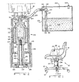
- Figure 1 is a perspective view of a chair incorporating a preferred embodiment of the present invention with a remotely located pressurized tank;
- Figure 2 is a sectional view of the pneumatic lifting mechanism of Figure 1 taken along the line 2-2 of Figure 1;
- Figure 3 is a perspective view of a chair incorporating an embodiment of the present invention wherein the tanks are in concentric relationship;
- Figure 4 is a sectional view of the pneumatic lifting mechanism of Figure 3 taken along the line 4-4 of Figure 3;
- Figure 5 is a sectional view of the hydraulic lifting mechanism of Figure 4 taken along the line 5-5;
- Figure 6 is a sectional view of an embodiment of the present invention wherein the tanks are disposed in stacked relationship; and,
- Figure 7 is a sectional view of the embodiment of Figure 6 with the expandable tank in its expanded position.
- Corresponding reference characters indicate corresponding parts throughout the several views of the drawings.
- The exemplifications set out herein illustrate a preferred embodiment of the invention, in one form thereof, and such exemplifications are not to be construed as limiting the scope of the disclosure or the scope of the invention in any manner.
- Referring to Fig. 1 a
chair assembly 10 is shown comprising a base 12 includingcasters 14. Aseat 16 is supported on the base and has anarm 18. Thepneumatic lifting mechanism 20 is shown located below theseat 16 and intermediate theseat 16 andbase 12.Mechanism 20 comprises a lowercylindrical housing cover 24 and an uppercylindrical housing cover 34. A sealed tank orchamber 26 is shown located inarm 18 and ahollow conduit 28 is shown leading fromtank 26 tomechanism 20. Acontrol 30 is shown located on the side ofarm 18 for controlling the operation ofmechanism 20 as further explained hereinbelow. Areciprocable support shaft 32 is provided at the upper end ofmechanism 20 for reciprocably supporting asupport platform 36 upon whichchair seat 16 rests. -
Mechanism 20, in a preferred embodiment, is shown in Fig. 2 as follows. Athrust bearing 38 is located in a lower portion of the mechanism,adjacent base 12 for rotatably supporting the lifting mechanism and the chair seat.Thrust bearing 38 rests on abottom portion 50 of cylindrical housing portion orshroud 24. Rotatingshaft 40 extends upwardly from anenlarged portion 42 located in the bottom portion ofhousing portion 24, and has anupper portion 44 secured inaperture 45. Asleeve bearing 48 having a flange thereon is positioned betweenhousing cover portions Housing portion 34 or shroud can therefore rotate with respect tohousing portion 24.Housing portions guide tube 46 extends upwardly from a supportingbottom portion 52 ofhousing portion 34 to prevent lateral movement ofshaft 40. Atelescoping tube member 56 is slidably reciprocably received withinhousing portion 34.Spacer 54 is inserted betweenhousing portion 34 andinner tube 56 and serves as a sleeve bearing surface therebetween. Thus,housing portion 24, bottom 50 and the bottom race of bearing 38 are stationary.Housing portion 34, top race of bearing 38,shaft 42,bottom portion 52,tube 46,support member 62, andtelescoping tube 56 rotate together and are supported by bearing 38. - A
bottom portion 58 of telescopinginner tube 56 has anaperture 60 provided therein to provide clearance betweensupport member 62 andbottom portion 58 asbottom portion 58 travels upwardly. While bearing 38 has been shown located in the lower portion of the mechanism it should be understood that bearing 38 can also be located upwardly in the mechanism. For instance,aperture 45 could be provided with a ball bearing so thatupper portion 44 ofshaft 40 is stationary andmember 62 rotates with respect toshaft 40. - A diaphragm or
sock 64 is provided in the upper portion ofcover 34 and is sealingly connected to an upper portion ofsupport member 62.Diaphragm 64 is in the form of a rolling sock or flexible bag and encloses a volume which is variable. The volume of the bag is increased by rolling the sides thereof so that the sides no longer fold in upon themselves as shown in Fig. 6 but instead are extended as shown in Fig. 7 and further described hereinafter.Support member 62 has anaperture 45 therein for rotatably receivingportion 44 ofshaft 40. The upper portion ofsupport member 62 has an undercutportion 74 whereby the edge portion ofdiaphragm 64 is captured thereby and retained therein by means ofcrimp ring 68 to make a sealing connection betweendiaphragm 64 andsupport member 62. - The opposite end of
diaphragm 64 is sealingly connected by means of a crimp ring to aplug 70 received in the upper opening ofdiaphragm 64.Plug 70 has an undercutportion 76 wherebydiaphragm 64 is sealingly captured in this undercut portion and is secured to plug 70 by means ofcrimp ring 72. It can be seen that this arrangement provides for theflexible bag 64 to have avariable volume 71. The advantage of this novel rollingsock chamber 64 is the provision of a variable volume chamber without the need for sliding seals as required by the prior art structures and as described hereinabove. The sock orbag 64 is sealed to plug 70 andsupport member 62 by means of a very simple and reliable sealing structure without the need for moving parts. The rolling action ofdiaphragm 64 permits the elimination of sliding seals yet retains the advantages of a variable volume chamber in a lifting mechanism. - Incompressible
hydraulic fluid 66 is provided for filling thevolume 71. Flexiblewalled chamber 64 is confined intube 56 and supported bymember 62. The expansion ofvolume 71 must therefore take place in the upward direction when incompressible hydraulic fluid is added tovolume 71. As the volume expandschamber 64 in the upward direction, the expansion will generate an upward lifting force onsupport shaft 32 andplatform 36 to liftchair seat 16. - Similarly, when a downward force acts on
platform 36, and is transmitted byshaft 32 tobag 64, the hydraulic fluid will be forced out ofbag 64 to return tochamber 26 and thereby allowingseat 16 to descend. As explained hereinafter, a valve is used to control transfer of fluid between the chambers. - Continuing to refer to Fig. 2, it can be seen that an
aperture 79 is provided inplug 70 for allowing ingress and egress of hydraulic fluid to and fromvolume 71. A threadedfitting 78 is provided for engagement with threadedportion 80 ofplug 70. Another threaded fitting 82 is provided intop support member 81 at right angles to fitting 78. Annularupstanding ridges 86 are provided onportion 84 of fitting 82 to engage withtube 28 and to securetube 28 to fitting 82 as is conventional.Tube 28 is shown with a break therein to indicate thattube 28 can be of any desired length. In the describedembodiments chamber 26 has rigid walls and is shown located remotely frommechanism 20. However, it should be understood thattank 26 may have either a fixed or variable volume and may have either flexible or rigid walls, since the function oftank 26 is to serve as holding reservoir for hydraulic working fluid.Tank 26 can be located at any location in the chair or remote therefrom. As illustrated in Fig. 1, the tank is located in thearm 18 of the chair. However, it should be understood thattank 26 can be located at any convenient location either within the article of furniture or outside of it. For instance, if the article furniture in which the mechanism is to be used were a table,tank 26 could conveniently be mounted underneath the table top. -
Chamber 26 is sealed with the exception of an opening through whichtube 28 extends by means of a fitting 90.Chamber 26 contains incompressiblehydraulic fluid 106 above whichpressurized gas 104 is provided. A fitting 102 is sealingly secured in a top portion of the tank for permitting hydraulic fluid gas to be inserted intotank 26. Acontrol valve 30 is provided for the mechanism and in this embodiment is shown as being completely housed intank 26. It should be understood that the valving mechanism can be provided at any convenient location such as for instance intube 28. - Continuing now with reference to Fig. 2, it can be seen that
valving mechanism 30 comprises an ON/OFF valve 88, a connectingtube 92, acheck valve 94 and a bypass orifice 100. Checkvalve 94 includes acheck valve ball 96 to sealorifice 98 when fluid flow is intotank 26. In the preferred embodiment, orifice 100 is much smaller thanorifice 98. It should be readily apparent to those skilled in the art that different types of check valves and ON/OFF valves may be used with this mechanism. Orifice 100 is a small passage for bypassingcheck valve 94. - In the operation of
valving mechanism 30, it can be seen that, whenvalve 88 is opened, liquid is allowed to pass throughtube 92. If in the illustrated embodiment the flow of liquid is in the upward direction, fluid pressure onball 96 will move it away fromorifice 98 whereby fluid will entertube 92 throughorifice 98 and orifice 100. However, when the flow of fluid is in the opposite or downward direction pressure onball 96 will cause it to seat inorifice 98 thereby closing off the orifice so that fluid can only pass fromtube 92 intochamber 26 by, means of bypass orifice 100.Valving mechanism 30 therefore comprises a reliable and simple valve structure having a greater fluid flow rate in one direction than the opposite direction. - It should benoted that location of the orifices in
valving mechanism 30 allows only incompressible hydraulic fluid to be transferred fromtank 26 tovolume 66. If gas were admitted intobag 64, the chair seat suspension would have a spongy feel to it, which is undesirable, as explained hereinabove. - In operation, the mechanism functions as follows. Some hydraulic liquid is admitted into
bag 64 and fills thevolume 71 inbag 64. The remainder of thehydraulic liquid 106 is admitted intochamber 26.Pressurized gas 104 is admitted intochamber 26. Whenvalve 88 is opened, andseat 16 is not occupied the pressure of thegas 104 onincompressible fluid 106 will force the fluid through orifice 100 andorifice 98 intotube 92 from whence it will pass throughvalve 88,tube 28 and intobag 64. As agreater liquid volume 66 occupies rollingsock diaphragm 64, it will forcediaphragm 64 to expand upwardly, enlargingvolume 71 and thereby pressing onplug 70 and forcingtop support member 81 upwardly together withshaft 32 andsupport platform 36.Chair seat 16 will therefore move upwardly untilvalve 88 is closed. Whenvalve 88 is closed, the seat cannot move downwardly because of the incompressibility offluid 66 inbag 64. As explained hereinabove,bag 64 is constructed to have flexible walls. However, the walls should not stretch, and the material of which diaphragm 64 is constructed must therefore be chosen to be of sufficient thickness to prevent stretching under pressure of fluid in the bag. However, the material must be flexible enough to allow the bag to flex and act as a rolling sock to vary the size ofvolume 71. A preferable material fordiaphragm 64 is neoprene rubber since this material is sufficiently flexible and is resistant to oil. The hydraulic fluid used is preferably water mixed with hydraulic oil. - If it is desired to
lower chair seat 16, a weight is placed on the chair seat such as for instance by means of an occupant of the chair andvalve 88 is opened. The weight of the occupant will cause pressure on the fluid involume 71 causing it to flow through opening 79 inplug 70, throughtube 28 andvalve 88 intotube 92. The fluid pressure onball 96 will causeball 96 to seat inorifice 98 whereby the fluid can only pass intotank 26 through orifice 100. Orifice 100 is sized so that the flow through it is sufficiently slow to allow the downward speed of the chair seat to be comfortable for the chair occupant. In addition, the flow should be sufficiently slow so that the occupant can choose the exact position in which he wants to stop the descent ofseat 16. If the fluid flow in the downward direction of the chair were made too fast, great coordination would be needed by the occupant to stop the downward movement of the chair at the precise desired point. - What has therefore been provided is a very simple and efficient mechanism for raising and lowering the chair seat. No sliding seals are used in the construction of the mechanism whereby leakage is eliminated. Furthermore, no pumps are needed in order to provide upward movement of the mechanism since the
pressurized gas 104 provides the pumping function. Additionally, the control can be located anywhere in the chair including the arm portion of the chair or the side of the chair seat where it is easily accessible to the user. The mechanism can also be incorporated in articles of furniture other than chairs, such as for instance tables, since the tank can be located anywhere in a convenient location so that the mechanism will not be bulky and take up too much space. It can also be seen that in the illustrated chair embodiment the entire upperstructure including housing 34,tube 28 andtank 26 rotates with the chair seat. By this arrangement the control and tank can be located remotely in the chair. - The function provided by
compressed gas 104 inchamber 26 is to force hydraulic fluid fromchamber 26 intobag 64. In some cases it may be possible that alternative embodiments can be provided wherein the fluid transfer function is provided by other means. For instance, a pump could be provided to transfer fluid throughconduit 28. Alternatively,chamber 26 could be expandable and means could be provided to expand and collapsechamber 26 so as to transfer fluid between the two chambers. - Turning now to Figs. 3, 4, and 5 an alternate embodiment of the invention is shown as follows. The chambers for containing the hydraulic liquid are arranged concentrically rather than remotely from each other as shown in Fig. 1. Thus, by reference to Fig. 3 it is shown that the
arm 18 of the chair does not contain a tank.Tube 28 loops frommechanism 20 upwardly along the bottom of the seat portion ofchair 16 and then back tomechanism 20.Control valve 30 inhouse loop 28 is located at the side of the chair seat portion for easy accessibility by the seat occupant. - Lower
cylindrical housing cover 24 andbottom portion 50 thereof are stationary.Stationary support column 40 extends upwardly from the bottom portion in whichthrust bearing 38 is provided.End 44 ofshaft 40 is received inrecess 45 ofsupport member 62.Guide tube 46 surroundsshaft 40 to prevent lateral movement thereof.Diaphragm 64 is enclosed incylindrical member 56.Diaphragm 64 is sealingly connected to supportmember 62 withcrimp ring 68 and to plug 70 withcrimp ring 72.Circumferential chamber 108 surroundscylinder 56 and is spaced therefrom by means ofring spacers 114, three of which are provided in the illustrated embodiment.Spacers 114 form sleeve bearing surfaces for telescopingcylinder 56.Chamber 108 comprises two cylindrical walls includinginner wall 112 andouter wall 110. An upper wall 111 and alower wall 113complete chamber 108.Chamber 108 is sealed and containshydraulic fluid 106 andpressurized gas 104 as indicated.Chamber 108 also has a fitting 102 to allow the addition of hydraulic fluid and pressurized gas to the chamber. A fitting 116 is also provided in an aperture in top wall 111 ofchamber 108 for transfer of hydraulic fluid to the chamber.Conduit 28 connects to fitting 116 in a conventional manner such as by the inclusion of ridges on the fitting for engagement withconduit 28.Flexible conduit 28 connects toconnector 84 havingridges 86 thereon as explained hereinabove in connection with Fig. 2.Chamber 108 is rotatingly received inhousing cover 24 and is spaced therefrom by means ofspacer 48 which forms a sleeve bearing.Spacers 48 can be constructed of plastic as explained hereinabove in connection with Fig. 2. - Fig. 5 shows a sectional view taken along the line 5-5 of Fig. 4 and shows that all parts sectioned by line 5-5 are cylindrical.
- In operation, cylindrical
inner tube 56 moves as a unit with top support-member 81 as fluid is added or removed fromvolume 66 ofbag 64.Rings 114 form bearing surfaces betweenwall 112 ofchamber 108 andtube 56.Control valve 30 comprises a simple pinch-offvalve 118, as illustrated. However, it should be understood thatvalve 30 can comprise any one of a variety of valves including the two speed valve of the embodiment of Fig. 2. Thus, asvalve 118 is squeezed by the operator to open the same, fluid will transfer frompressurized chamber 108 through fitting 116 andtube 28 intovolume 71. However, if a weight is placed upon the chair seat such as by an occupant, the flow of liquid will be in reverse fromvolume 71 tochamber 108 whenvalve 118 is opened. - It should be noted that fitting 116 extends into the bottom portion of
chamber 108 so that only liquid will be transferred between the two chambers. It should also be noted thatbag 64 contains only liquid. As described hereinabove, if gas were admitted intobag 64 the seat support would have a spongy feel to it, which is undesirable. - Turning now to Fig. 6, an alternate embodiment of the invention is shown wherein the two chambers are disposed in stacked relationship. Then in this embodiment the entire lifting mechanism can be located in the base of the chair or the like. A
base 12 is again shown attached to lowercylindrical housing cover 24.Shaft 40 is provided for supportingsupport member 62 to which a bottom portion ofdiaphragm 64 is secured bycrimp ring 68 as explained hereinabove. The mechanism is shown in its lowermost position. Athrust bearing 38 is provided in the lower portion ofhousing cover 24 for supportingbottom portion 52 of uppercylindrical housing cover 34. The top portion ofdiaphragm 64 is secured to plug 70 by means ofcrimp ring 72.Plug 70 has anaperture 79 therein for permitting hydraulic fluid to flow into and out ofvolume 71. - Disposed
superjacent plug 70 is aseparator member 120 having anaperture 121 therein to allow atube 124 to extend therethrough for enabling hydraulic fluid to be transferred to and fromvolume 71. Achamber 123 located aboveseparator 120 hasside walls 126 to form the sealedchamber 123 including atop wall portion 122.Tubes apertures top wall 122 for connection totube 28.Tube 16 extends into the bottom portion ofchamber 123 whereby only hydraulic fluid will be transferred betweenvolume 71 andchamber 123.Shaft 32 is secured totop support surface 128 andconduit 28 extends through anopening 130 inupper portion 132 ofcylindrical wall 126. - In operation, as pinch-off
valve 118 is operated, hydraulic fluid transfers under pressure ofgas 104 throughtube 116,conduit 28 andtube 124 intovolume 71 thereby causingbag 64 to exert an upward force onplug 70 andseparator 120. The upward force is transmitted tocylindrical wall 126 wherebycylindrical wall 126,separator 120 andtop support surface 128 will rise upwardly. When an occupant is seated inchair seat 16, a downward force onplatform 36 andshaft 32 causes a force to be transmitted to plug 70 thereby squeezingbag 64 and forcing the hydraulic fluid to flow in a reverse direction throughtube 124,conduit 28 andtube 116 back intochamber 123 and allowingshaft 32 to descend. - It should be understood that while
valve 118 is shown schematically as a simple pinch-off valve, it can comprise any one of a variety of valves including the two speed valve of the embodiment of Fig. 2 to control fluid flow throughconduit 28 and to enable the transfer of fluid betweenvolume 71 andchamber 123. - As explained above, in some cases it may be possible that alternative means could be provided to transfer fluid from chamber 23 to
volume 71, for instance, a pump could be provided. Alternatively,chamber 123 could be constructed to have a variable volume and means could be provided to expand and shrink the volume. - Fig. 7 discloses the embodiment of Fig. 6 with
expandable bag 64 in its expanded position. By comparing Fig. 6 with Fig. 7 it can be seen thatvolume 71 in Fig. 7 is much larger thanvolume 71 of Fig. 6 and that the bottom portion ofbag 64 is not folded back upon itself to the same extent as shown in Fig. 6. It can also be seen thatcover 34 andchamber 123 have moved upwardly as a unit under pressure from the hydraulic fluid involume 71 to supportshaft 32 andplatform 36 in an elevated position. By reference to this figure it can also be seen thatconduit 28 has moved upwardly together with the remainder of the working parts of the mechanism. The walls ofbag 64 are in contact with the inside oftank wall 126 so thatvolume 71 can expand only in the upward direction. - The operation of
bag 64 is similar in all embodiments shown. In the interest of clarity, the expanded position ofbag 64 has only been shown for the embodiment of Fig. 7. However, by reference to the embodiments of Figs. 1-5 it can be seen thatbag 64 operates the same way in those embodiments as in the embodiment shown in Figs. 6 and 7.
Claims (9)
characterised in that the second fluid filled chamber (7) is at least partly defined by a flexible wall (64) to accommodate variations in volume (71) of the second fluid filled chamber.
Applications Claiming Priority (2)
| Application Number | Priority Date | Filing Date | Title |
|---|---|---|---|
| US06/668,307 US4593951A (en) | 1984-11-05 | 1984-11-05 | Hydraulic chair lift mechanism |
| US668307 | 1984-11-05 |
Publications (2)
| Publication Number | Publication Date |
|---|---|
| EP0183360A1 EP0183360A1 (en) | 1986-06-04 |
| EP0183360B1 true EP0183360B1 (en) | 1989-07-26 |
Family
ID=24681825
Family Applications (1)
| Application Number | Title | Priority Date | Filing Date |
|---|---|---|---|
| EP85307197A Expired EP0183360B1 (en) | 1984-11-05 | 1985-10-08 | Hydraulic chair lift mechanism |
Country Status (4)
| Country | Link |
|---|---|
| US (2) | US4593951A (en) |
| EP (1) | EP0183360B1 (en) |
| DE (1) | DE3571748D1 (en) |
| ES (1) | ES8700035A1 (en) |
Families Citing this family (21)
| Publication number | Priority date | Publication date | Assignee | Title |
|---|---|---|---|---|
| GB2219044B (en) * | 1988-05-24 | 1992-07-29 | John Wang | Pressure actuated assembly extendable by fluid pressure and retractable by spring action |
| US5234187A (en) * | 1992-06-02 | 1993-08-10 | Steelcase Inc. | Chair height adjustment mechanism |
| US5366275A (en) * | 1993-06-16 | 1994-11-22 | L & P Property Management Company | Gas operated foot stool |
| US5511759A (en) * | 1994-05-26 | 1996-04-30 | Steelcase, Inc. | Hydraulic chair height adjustment mechanism |
| US6009815A (en) * | 1995-01-27 | 2000-01-04 | Proco, Inc. | Stabilized table, stabilizer for tables, and method of stabilizing tables |
| US5810439A (en) * | 1996-05-09 | 1998-09-22 | Haworth, Inc. | Forward-rearward tilt control for chair |
| US6527007B2 (en) * | 1998-12-16 | 2003-03-04 | Carl Cheung Tung Kong | Fluid transfer system |
| US6755473B2 (en) * | 2000-11-22 | 2004-06-29 | Herman Miller, Inc. | Fluid control system for an office furniture device |
| US6828013B2 (en) | 2000-12-11 | 2004-12-07 | Exxonmobil Oil Corporation | Porous biaxially oriented high density polyethylene film with hydrophilic properties |
| US8012416B2 (en) * | 2005-08-30 | 2011-09-06 | Cytotherm, L.P. | Thawing biological material using a sealed liquid bladder |
| CA2543704A1 (en) * | 2006-04-18 | 2007-10-18 | Baultar I.D. Inc. | Compact seat base with passive suspension independent of height adjustment |
| US8210109B1 (en) * | 2007-11-01 | 2012-07-03 | Thomas Gerret Dewees | Pneumatic adjustable-height table |
| TWM365308U (en) * | 2009-06-05 | 2009-09-21 | Kind Shock Hi Tech Co Ltd | Bicycle seat stand pipe structure with adjustable capability |
| US8662588B1 (en) | 2012-06-21 | 2014-03-04 | Fabio G. Delmestri | Chair base with scissor lift |
| US9441426B2 (en) | 2013-05-24 | 2016-09-13 | Oil States Industries, Inc. | Elastomeric sleeve-enabled telescopic joint for a marine drilling riser |
| CN105755750B (en) * | 2016-04-13 | 2024-04-02 | 青岛海尔洗衣机有限公司 | Washing machine footing and washing machine with automatic leveling function |
| CN105755757B (en) * | 2016-04-13 | 2024-01-12 | 青岛海尔洗衣机有限公司 | Washing machine footing and washing machine with automatic leveling function |
| CN108278452B (en) * | 2017-01-06 | 2020-12-22 | 青岛海尔洗衣机有限公司 | Footing for household appliance and household appliance |
| CN108317209B (en) * | 2017-01-16 | 2020-11-03 | 青岛海尔洗衣机有限公司 | Footing for household appliance and household appliance |
| US10668968B2 (en) * | 2017-06-30 | 2020-06-02 | Sram, Llc | Seat post assembly |
| CN108937287B (en) * | 2018-08-14 | 2021-10-15 | 安吉隆博家具有限公司 | High strength swivel chair bracket |
Family Cites Families (29)
| Publication number | Priority date | Publication date | Assignee | Title |
|---|---|---|---|---|
| CA783416A (en) * | 1968-04-23 | Stuckenberger Anton | Seat suspension | |
| DD70218A (en) * | ||||
| US247142A (en) * | 1881-09-13 | Syringe bulb and valve | ||
| US1651506A (en) * | 1923-04-17 | 1927-12-06 | Berninghaus Eugene | Vertically-adjustable chair |
| US2490823A (en) * | 1946-10-14 | 1949-12-13 | Howard H Manning | Hydraulic-pneumatic system |
| DE1605908C3 (en) * | 1951-01-28 | 1974-05-30 | Adolf Dipl.-Ing. 8000 Muenchen Auer | Hydrodynamic-mechanical step change gear for fan tools, in particular motor vehicles |
| US2906095A (en) * | 1956-12-13 | 1959-09-29 | Honeywell Regulator Co | Transmitting apparatus |
| US2961033A (en) * | 1958-01-20 | 1960-11-22 | Milsco Mfg Company | Air spring supported seat |
| US3005444A (en) * | 1959-07-27 | 1961-10-24 | Dumore Company | Control means for fluid actuated work cylinders |
| US3143332A (en) * | 1962-02-23 | 1964-08-04 | Lee S Watlington | Hydraulic lift support for chair |
| US3226931A (en) * | 1964-01-06 | 1966-01-04 | Sperry Rand Corp | Fluid diaphragm isolator |
| US3286970A (en) * | 1964-03-23 | 1966-11-22 | American Radiator & Standard | Bathlift |
| NL137530C (en) * | 1965-07-09 | |||
| US3438607A (en) * | 1966-03-28 | 1969-04-15 | Omark Air Controls Inc | Valve for evacuator |
| US3386345A (en) * | 1966-08-01 | 1968-06-04 | John F. Taplin | Rolling diaphragm device having centering button on diaphragm and having piston rod rotatable relative to piston |
| US3381926A (en) * | 1966-10-20 | 1968-05-07 | Edward E. Fritz | Adjustable stool |
| DE1605927C3 (en) * | 1967-12-22 | 1979-04-26 | Adolf Dipl.-Ing. 8000 Muenchen Auer | Air suspension vehicle seat |
| US3594040A (en) * | 1968-12-31 | 1971-07-20 | Edwin P Monroe | Suspension device |
| GB1416712A (en) * | 1972-03-14 | 1975-12-03 | Macmanus J | Apparatus for use in depositing aerated food products |
| JPS5016247A (en) * | 1973-06-18 | 1975-02-20 | ||
| US3865341A (en) * | 1973-08-08 | 1975-02-11 | Den Tal Ez Mfg Co | Dental stool for dentist and dental assistant |
| JPS52159313U (en) * | 1976-05-28 | 1977-12-03 | ||
| DE2630483A1 (en) * | 1976-07-07 | 1978-01-12 | Suspa Federungstech | HEIGHT-ADJUSTABLE CHAIR OR TABLE BASE |
| US4074887A (en) * | 1976-09-20 | 1978-02-21 | Hale Dean H | Power unit for a medical or like stool |
| US4077601A (en) * | 1976-12-13 | 1978-03-07 | Dick George M | Adjustable pinch clamp |
| US4355783A (en) * | 1978-11-06 | 1982-10-26 | Cutter Laboratories, Inc. | Flow control device |
| DE3040483A1 (en) * | 1980-10-28 | 1982-06-16 | Stabilus Gmbh, 5400 Koblenz | GAS SPRING WITH HYDRAULIC BLOCKING |
| GB2095364B (en) * | 1981-03-24 | 1985-07-24 | Wipac Group Sales | Adjustable fluid support devices for swivel chairs |
| US4465266A (en) * | 1982-03-08 | 1984-08-14 | Hale Chairco Corporation | Power unit for medical and like stools and chairs |
-
1984
- 1984-11-05 US US06/668,307 patent/US4593951A/en not_active Expired - Fee Related
-
1985
- 1985-09-06 US US06/773,337 patent/US4621868A/en not_active Expired - Fee Related
- 1985-10-08 EP EP85307197A patent/EP0183360B1/en not_active Expired
- 1985-10-08 DE DE8585307197T patent/DE3571748D1/en not_active Expired
- 1985-11-04 ES ES548505A patent/ES8700035A1/en not_active Expired
Also Published As
| Publication number | Publication date |
|---|---|
| EP0183360A1 (en) | 1986-06-04 |
| US4621868A (en) | 1986-11-11 |
| ES8700035A1 (en) | 1986-10-01 |
| DE3571748D1 (en) | 1989-08-31 |
| US4593951A (en) | 1986-06-10 |
| ES548505A0 (en) | 1986-10-01 |
Similar Documents
| Publication | Publication Date | Title |
|---|---|---|
| EP0183360B1 (en) | Hydraulic chair lift mechanism | |
| US4592590A (en) | Hydraulic lifting mechanism for a chair or the like using a two phase working fluid | |
| US4415135A (en) | Support devices for swivel chairs | |
| FI88357B (en) | ADJUSTMENT OLYEPNEUMATISK CONSOLE SPECIFICALLY FOR OFFICE OFFICE FOR MITTS | |
| US3913901A (en) | Resilient supporting column of adjustable length | |
| JPH04231013A (en) | Cylinder making possible adjustment of length, being specially used as supporting column of chair, seat or the like | |
| US6056251A (en) | Adjustable-height column with depth spring action | |
| KR20050076834A (en) | Adjustable-height chair column | |
| JP3073521B2 (en) | Exercise equipment | |
| US5028037A (en) | Automatic lifting apparatus | |
| US4605203A (en) | Pneumatic jack | |
| US2980013A (en) | Hydraulic press apparatus | |
| JPS5926816B2 (en) | Variable displacement hydraulic pressure combined type accumulator | |
| CN107246451B (en) | Pressure adjustable gas spring | |
| US4074887A (en) | Power unit for a medical or like stool | |
| US5294086A (en) | Adjustable oleopneumatic amortized support column, for chairs and armchairs | |
| CA1038852A (en) | Jack-pump device | |
| KR100616452B1 (en) | A gas cylinder having an automatic return and height-adjustment functions in a chair | |
| US5396535A (en) | X-ray apparatus comprising a hydraulic system | |
| JPH0762473B2 (en) | Pump device | |
| EP0215752A2 (en) | Piston pump, particularly for inflating tyres, mattresses, sports equipment and the like | |
| US20020195535A1 (en) | Height adjustment mechanism | |
| JP2605487B2 (en) | Chair lumbar support device | |
| JP3002032U (en) | Chair lift equipment | |
| JPH06102Y2 (en) | Lifting mechanism in patient lifting device |
Legal Events
| Date | Code | Title | Description |
|---|---|---|---|
| PUAI | Public reference made under article 153(3) epc to a published international application that has entered the european phase |
Free format text: ORIGINAL CODE: 0009012 |
|
| AK | Designated contracting states |
Kind code of ref document: A1 Designated state(s): DE FR GB |
|
| 17P | Request for examination filed |
Effective date: 19860819 |
|
| 17Q | First examination report despatched |
Effective date: 19870923 |
|
| GRAA | (expected) grant |
Free format text: ORIGINAL CODE: 0009210 |
|
| AK | Designated contracting states |
Kind code of ref document: B1 Designated state(s): DE FR GB |
|
| REF | Corresponds to: |
Ref document number: 3571748 Country of ref document: DE Date of ref document: 19890831 |
|
| ET | Fr: translation filed | ||
| PLBE | No opposition filed within time limit |
Free format text: ORIGINAL CODE: 0009261 |
|
| STAA | Information on the status of an ep patent application or granted ep patent |
Free format text: STATUS: NO OPPOSITION FILED WITHIN TIME LIMIT |
|
| 26N | No opposition filed | ||
| PGFP | Annual fee paid to national office [announced via postgrant information from national office to epo] |
Ref country code: GB Payment date: 19920928 Year of fee payment: 8 |
|
| PGFP | Annual fee paid to national office [announced via postgrant information from national office to epo] |
Ref country code: FR Payment date: 19921005 Year of fee payment: 8 |
|
| PGFP | Annual fee paid to national office [announced via postgrant information from national office to epo] |
Ref country code: DE Payment date: 19921021 Year of fee payment: 8 |
|
| PG25 | Lapsed in a contracting state [announced via postgrant information from national office to epo] |
Ref country code: GB Effective date: 19931008 |
|
| GBPC | Gb: european patent ceased through non-payment of renewal fee |
Effective date: 19931008 |
|
| PG25 | Lapsed in a contracting state [announced via postgrant information from national office to epo] |
Ref country code: FR Effective date: 19940630 |
|
| PG25 | Lapsed in a contracting state [announced via postgrant information from national office to epo] |
Ref country code: DE Effective date: 19940701 |
|
| REG | Reference to a national code |
Ref country code: FR Ref legal event code: ST |