EP0183257A2 - Sodium-sulfur cell block - Google Patents
Sodium-sulfur cell block Download PDFInfo
- Publication number
- EP0183257A2 EP0183257A2 EP85115088A EP85115088A EP0183257A2 EP 0183257 A2 EP0183257 A2 EP 0183257A2 EP 85115088 A EP85115088 A EP 85115088A EP 85115088 A EP85115088 A EP 85115088A EP 0183257 A2 EP0183257 A2 EP 0183257A2
- Authority
- EP
- European Patent Office
- Prior art keywords
- cell
- sodium
- terminal
- sulfur
- block according
- Prior art date
- Legal status (The legal status is an assumption and is not a legal conclusion. Google has not performed a legal analysis and makes no representation as to the accuracy of the status listed.)
- Granted
Links
Images



Classifications
-
- H—ELECTRICITY
- H01—ELECTRIC ELEMENTS
- H01M—PROCESSES OR MEANS, e.g. BATTERIES, FOR THE DIRECT CONVERSION OF CHEMICAL ENERGY INTO ELECTRICAL ENERGY
- H01M10/00—Secondary cells; Manufacture thereof
- H01M10/36—Accumulators not provided for in groups H01M10/05-H01M10/34
- H01M10/39—Accumulators not provided for in groups H01M10/05-H01M10/34 working at high temperature
- H01M10/3909—Sodium-sulfur cells
-
- H—ELECTRICITY
- H01—ELECTRIC ELEMENTS
- H01M—PROCESSES OR MEANS, e.g. BATTERIES, FOR THE DIRECT CONVERSION OF CHEMICAL ENERGY INTO ELECTRICAL ENERGY
- H01M50/00—Constructional details or processes of manufacture of the non-active parts of electrochemical cells other than fuel cells, e.g. hybrid cells
- H01M50/50—Current conducting connections for cells or batteries
- H01M50/528—Fixed electrical connections, i.e. not intended for disconnection
-
- Y—GENERAL TAGGING OF NEW TECHNOLOGICAL DEVELOPMENTS; GENERAL TAGGING OF CROSS-SECTIONAL TECHNOLOGIES SPANNING OVER SEVERAL SECTIONS OF THE IPC; TECHNICAL SUBJECTS COVERED BY FORMER USPC CROSS-REFERENCE ART COLLECTIONS [XRACs] AND DIGESTS
- Y02—TECHNOLOGIES OR APPLICATIONS FOR MITIGATION OR ADAPTATION AGAINST CLIMATE CHANGE
- Y02E—REDUCTION OF GREENHOUSE GAS [GHG] EMISSIONS, RELATED TO ENERGY GENERATION, TRANSMISSION OR DISTRIBUTION
- Y02E60/00—Enabling technologies; Technologies with a potential or indirect contribution to GHG emissions mitigation
- Y02E60/10—Energy storage using batteries
Definitions
- the present invention relates to a sodium-sulfur cell block, and particularly to a sodium-sulfur cell block which is suited for absorbing thermal stress generated across common terminals when the sodium-sulfur cells are provided in a plurality of numbers, and which is suited to firmly secure the single cells.
- the sodium-sulfur cell has heretofore been known as a secondary cell of the type of operating at high temperatures, which is capable of being charged or discharged at a temperature of about 300°C to about 350°C.
- the sodium-sulfur cells are often used being combined in a plurality of numbers, resulting in a block.
- single cells 2 are arranged in a plurality of numbers in parallel in a frame 1 as shown in Fig. 4.
- the individual cells are connected at both ends in the direction of long axis to common terminals 4 via single cell terminals 3 as shown in Fig. 5 which is a section view along the line A-A of Fig. 4.
- the single cell terminals 3 are fastened by bolts to the common terminals 4 as shown in Fig. 6, and are further welded to the sodium-sulfur cells.
- the sodium-sulfur cells are used at a temperature of from 300°C to 350°C. Therefore, the cylindrical single cells are particularly elongated in the direction of long axis to affect the common terminals 4 via cell terminals 3. Accordingly, the common terminals 4 are often damaged.
- Japanese Utility Model Laid-Open No. 57862/1984 discloses another sodium-sulfur cell block in which the single cells are tilted. With this block, however, the single cells are subject to swing when it is moved, just like the above-mentioned block of the type supported by wires.
- the present invention is designed to provide a sodium-sulfur cell block which absorbs thermal stress that generates between the single cells and the common terminals, and which prevents said common terminals from breaking.
- the present invention is concerned with a sodium-sulfur cell block having a plurality of sodium-sulfur cells, both ends each of which in the direction of long axis being intimately attached to, and held by, common terminals, wherein at least one end of each of the sodium-sulfur cells in the direction of long axis is cantilevered at the common terminal.
- Fig. 1 is a diagram showing the structure of a sodium-sulfur cell block according to an embodiment of the present invention, wherein the cell terminals 11 are welded in an L-shape to the lower portion of single cells 2 on the side opposite to the common terminal 4.
- the common terminal 11 is welded to the single cell 2 at a position where the center of the cell terminal 11 is located at a point where a tangential line of the single cell 2 in parallel with the common terminal 4 comes into contact with the single cell.
- length of the cantilever region is determined by taking into consideration the balance between the possible deformation when the cells are bing used and the size of the block.
- length of the cantilever region is set to be equal to the diameter of the single cell 2, as shown in Fig. 4. Length of the cantilever region of the cell terminal 11 can be adjusted by moving the common terminal 4 under the single cell 2 relative to the single cell 2.
- the common terminal 11 can also be contrived to well the common terminal 11 to a side portion of the single cell 2. In this case, however, the common terminal 11 must be twisted once to connect to the common terminal 4. The cell terminal 11 which is twisted is not desirable from the standpoint of absorbing the thermal stress of the single cell 2.
- the cell terminal 11 must have a thickness of several millimeters to absorb the thermal stress of the single cell 2 in the direction of long axis and to firmly hold the single cell 2. Further, the cell terminal 11 must have a width which is several times as great as the thickness thereof, so as to maintain a modulus of section for the external force other than the force in the direction of long axis. Depending upon the size of the single cell 2, however, thickness and width of the cell terminal 11 can be adjusted.
- the single cell is cantilevered at the lower end thereof in the direction of long axis.
- the single cell 2 can also be cantilevered at the upper end thereof by the cell terminal 11.
- the single cell can be cantilevered only at the upper end thereof.
- to fasten the single cell 2 to the common terminals 4 in a cantilevered manner both at the upper and lower ends thereof is difficult because it is difficult to determine the position in the direction of long axis and manufacturing process.
- the single cell 2 should be cantilevered at the lower end thereof.
- the cell terminal 11 is made of the same material as the common terminal 4, i.e., made of a material (usually copper) which forms the electrodes. Further, the cell terminal 11 is welded to the single cell 2 to firmly bond them together. The cell terminal 11 may be fastened to the single cell 2 by screws instead of being welded.
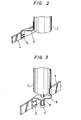
- Fig. 2 shows a cell terminal 11 of an L-shape like the embodiment of Fig. 4.
- the cell terminal 11 is joined to the single cell 2 on the same side as the common terminal 4.
- the cell terminal 11 is so welded that the center of the cell terminal 1 1 comes to a point where a tangential line in parallel with the common terminal 4 comes into contact with the single cell 2 on the same side as the common terminal 4.
- the cantilevered cell terminal 11 of this embodiment absorbs the thermal stress generated by the single cell 2 like the cell terminal that is shown in Fig. 1.
- the length consisting of the diameter of the single cell 2 and the cantilever region of the cell terminal 11 determines the size of the cell block in the lateral direction. From the standpoint of realizing a compact cell block of size, therefore, it is desired to adopt the embodiment of Fig. 1 in which the cantilever region of the cell terminal 11 is superposed on the diameter of the single cell 2.
- Fig. 3 shows the case where a pipe 7 is provided at the lower end of the single cell 2 in the embodiment of Fig. 1 to introduce an inert gas into the single cell 2.
- the cantilever region of the cell terminal 11 should be provided with a region to bypass the projection such as pipe.
- a circular reinforcing portion 12 should be provided on the side opposite to the bypassing region to produce increased strength against the external force of the lateral direction.
- the thermal stress that generates at a junction portion between the single cell and the common terminal is absorbed, and the common terminal is prevented from breaking. Furthermore, even if a portion of the single cell is broken, other single cells are not affected, and the external force is prevented from exerting on the common terminal.
Landscapes
- Chemical & Material Sciences (AREA)
- Chemical Kinetics & Catalysis (AREA)
- Electrochemistry (AREA)
- General Chemical & Material Sciences (AREA)
- Engineering & Computer Science (AREA)
- Manufacturing & Machinery (AREA)
- Secondary Cells (AREA)
- Connection Of Batteries Or Terminals (AREA)
Abstract
Description
- The present invention relates to a sodium-sulfur cell block, and particularly to a sodium-sulfur cell block which is suited for absorbing thermal stress generated across common terminals when the sodium-sulfur cells are provided in a plurality of numbers, and which is suited to firmly secure the single cells.
- The sodium-sulfur cell has heretofore been known as a secondary cell of the type of operating at high temperatures, which is capable of being charged or discharged at a temperature of about 300°C to about 350°C. The sodium-sulfur cells are often used being combined in a plurality of numbers, resulting in a block.
- According to the above sodium-sulfur cell block,
single cells 2 are arranged in a plurality of numbers in parallel in aframe 1 as shown in Fig. 4. The individual cells are connected at both ends in the direction of long axis tocommon terminals 4 viasingle cell terminals 3 as shown in Fig. 5 which is a section view along the line A-A of Fig. 4. - The
single cell terminals 3 are fastened by bolts to thecommon terminals 4 as shown in Fig. 6, and are further welded to the sodium-sulfur cells. - As mentioned above, however, the sodium-sulfur cells are used at a temperature of from 300°C to 350°C. Therefore, the cylindrical single cells are particularly elongated in the direction of long axis to affect the
common terminals 4 viacell terminals 3. Accordingly, thecommon terminals 4 are often damaged. - In addition to the above-mentioned sodium-sulfur cell block, a block has been proposed in which the individual cells are fastened to the common terminals via wires, as well as a block which employs a slide system for fastening the cell terminals to the common terminals. With the former block in which the single cells are fastened by wires, however, swinging develops when the sodium-sulfur cell block is moved. With the latter block, on the other hand, sparking occurs at the cell terminals that are supported in a sliding manner by the common terminals.
- Japanese Utility Model Laid-Open No. 57862/1984 discloses another sodium-sulfur cell block in which the single cells are tilted. With this block, however, the single cells are subject to swing when it is moved, just like the above-mentioned block of the type supported by wires.
- The present invention is designed to provide a sodium-sulfur cell block which absorbs thermal stress that generates between the single cells and the common terminals, and which prevents said common terminals from breaking.
- The present invention is concerned with a sodium-sulfur cell block having a plurality of sodium-sulfur cells, both ends each of which in the direction of long axis being intimately attached to, and held by, common terminals, wherein at least one end of each of the sodium-sulfur cells in the direction of long axis is cantilevered at the common terminal. With the thus constructed sodium-sulfur cell block of the present invention in which the single sodium-sulfur cells are cantilevered at the common terminal, thermal stress generated between the single cells and the common terminals while the sodium-sulfur cells are being used is absorbed, so that the common terminals are prevented from breaking.
-
- Figs. 1 to 3 are diagrams showing the structure of portions where single cells in a sodium-sulfur cell block of the present invention are joined to a common terminal;
- Fig. 4 is a section view showing a conventional sodium-sulfur cell block;
- Fig. 5 is a section view along the line A-A of Fig. 4 and
- Fig. 6 is a diagram showing a conventional structure for joining the single cells and the common terminals.
- Preferred embodiments of the sodium-sulfur cell block of the present invention will be described below in detail in conjunction with the accompanying drawings. In the following description, the portions corresponding to those mentioned in the background of the invention are denoted by the same reference numerals and are not explained.
- Fig. 1 is a diagram showing the structure of a sodium-sulfur cell block according to an embodiment of the present invention, wherein the
cell terminals 11 are welded in an L-shape to the lower portion ofsingle cells 2 on the side opposite to thecommon terminal 4. Thecommon terminal 11 is welded to thesingle cell 2 at a position where the center of thecell terminal 11 is located at a point where a tangential line of thesingle cell 2 in parallel with thecommon terminal 4 comes into contact with the single cell. - The longer the region other than the cantilever region (portion welded to the
common terminal 4 or the single cell 2) of thecell terminal 11, the more deformation is absorbed when thesingle cells 2 are being used. However, increasing the length of the cantilever region makes it difficult to realize a cell block of compact size. Therefore, length of the cantilever region is determined by taking into consideration the balance between the possible deformation when the cells are bing used and the size of the block. Usually, length of the cantilever region is set to be equal to the diameter of thesingle cell 2, as shown in Fig. 4. Length of the cantilever region of thecell terminal 11 can be adjusted by moving thecommon terminal 4 under thesingle cell 2 relative to thesingle cell 2. It can also be contrived to well thecommon terminal 11 to a side portion of thesingle cell 2. In this case, however, thecommon terminal 11 must be twisted once to connect to thecommon terminal 4. Thecell terminal 11 which is twisted is not desirable from the standpoint of absorbing the thermal stress of thesingle cell 2. - The
cell terminal 11 must have a thickness of several millimeters to absorb the thermal stress of thesingle cell 2 in the direction of long axis and to firmly hold thesingle cell 2. Further, thecell terminal 11 must have a width which is several times as great as the thickness thereof, so as to maintain a modulus of section for the external force other than the force in the direction of long axis. Depending upon the size of thesingle cell 2, however, thickness and width of thecell terminal 11 can be adjusted. - The above embodiment has been the case where the single cell is cantilevered at the lower end thereof in the direction of long axis. However, the
single cell 2 can also be cantilevered at the upper end thereof by thecell terminal 11. Furthermore, the single cell can be cantilevered only at the upper end thereof. However, to fasten thesingle cell 2 to thecommon terminals 4 in a cantilevered manner both at the upper and lower ends thereof, is difficult because it is difficult to determine the position in the direction of long axis and manufacturing process. Most desirably, therefore, thesingle cell 2 should be cantilevered at the lower end thereof. - Like the conventional art, the
cell terminal 11 is made of the same material as thecommon terminal 4, i.e., made of a material (usually copper) which forms the electrodes. Further, thecell terminal 11 is welded to thesingle cell 2 to firmly bond them together. Thecell terminal 11 may be fastened to thesingle cell 2 by screws instead of being welded. - Another embodiment of the invention will be described below.
- Fig. 2 shows a
cell terminal 11 of an L-shape like the embodiment of Fig. 4. However, what makes a difference is that thecell terminal 11 is joined to thesingle cell 2 on the same side as thecommon terminal 4. Thecell terminal 11 is so welded that the center of thecell terminal 11 comes to a point where a tangential line in parallel with thecommon terminal 4 comes into contact with thesingle cell 2 on the same side as thecommon terminal 4. - The
cantilevered cell terminal 11 of this embodiment absorbs the thermal stress generated by thesingle cell 2 like the cell terminal that is shown in Fig. 1. When the cell block is taken into consideration, however, the length consisting of the diameter of thesingle cell 2 and the cantilever region of thecell terminal 11 determines the size of the cell block in the lateral direction. From the standpoint of realizing a compact cell block of size, therefore, it is desired to adopt the embodiment of Fig. 1 in which the cantilever region of thecell terminal 11 is superposed on the diameter of thesingle cell 2. - Next, Fig. 3 shows the case where a
pipe 7 is provided at the lower end of thesingle cell 2 in the embodiment of Fig. 1 to introduce an inert gas into thesingle cell 2. In this case, the cantilever region of thecell terminal 11 should be provided with a region to bypass the projection such as pipe. In this case, furthermore, a circular reinforcingportion 12 should be provided on the side opposite to the bypassing region to produce increased strength against the external force of the lateral direction. - According to the sodium-sulfur cell block of the present invention as described above, the thermal stress that generates at a junction portion between the single cell and the common terminal is absorbed, and the common terminal is prevented from breaking. Furthermore, even if a portion of the single cell is broken, other single cells are not affected, and the external force is prevented from exerting on the common terminal.
Claims (9)
Applications Claiming Priority (2)
| Application Number | Priority Date | Filing Date | Title |
|---|---|---|---|
| JP59251378A JPS61131375A (en) | 1984-11-28 | 1984-11-28 | Sodium-sulfur battery assembly |
| JP251378/84 | 1984-11-28 |
Publications (3)
| Publication Number | Publication Date |
|---|---|
| EP0183257A2 true EP0183257A2 (en) | 1986-06-04 |
| EP0183257A3 EP0183257A3 (en) | 1987-03-25 |
| EP0183257B1 EP0183257B1 (en) | 1988-11-02 |
Family
ID=17221941
Family Applications (1)
| Application Number | Title | Priority Date | Filing Date |
|---|---|---|---|
| EP85115088A Expired EP0183257B1 (en) | 1984-11-28 | 1985-11-28 | Sodium-sulfur cell block |
Country Status (4)
| Country | Link |
|---|---|
| US (1) | US4678727A (en) |
| EP (1) | EP0183257B1 (en) |
| JP (1) | JPS61131375A (en) |
| DE (1) | DE3566062D1 (en) |
Cited By (2)
| Publication number | Priority date | Publication date | Assignee | Title |
|---|---|---|---|---|
| WO1992010006A1 (en) * | 1990-11-23 | 1992-06-11 | Chloride Silent Power Limited | A battery of high temperature cells |
| WO2012139839A3 (en) * | 2011-04-13 | 2013-01-10 | Robert Bosch Gmbh | Storage unit for storing electrical energy |
Families Citing this family (3)
| Publication number | Priority date | Publication date | Assignee | Title |
|---|---|---|---|---|
| US5578392A (en) * | 1995-02-17 | 1996-11-26 | Japan Storage Battery Co., Ltd. | Cylindrical cell, a cell pack, and a cell holder |
| DE19649225A1 (en) * | 1996-11-27 | 1998-05-28 | Nass Magnet Gmbh | Valve |
| EP2109906B1 (en) * | 2007-02-09 | 2016-09-07 | Johnson Controls Advanced Power Solutions LLC | Buss bar for batteries |
Family Cites Families (8)
| Publication number | Priority date | Publication date | Assignee | Title |
|---|---|---|---|---|
| US1647141A (en) * | 1926-12-10 | 1927-11-01 | Meyer William | Battery case |
| US2216666A (en) * | 1939-05-25 | 1940-10-01 | Hempel Allen | Battery connecting means |
| US3891462A (en) * | 1973-10-29 | 1975-06-24 | Union Carbide Corp | Galvanic cell structure |
| FR2305034A1 (en) * | 1975-03-17 | 1976-10-15 | Comp Generale Electricite | SODIUM-SULFUR BATTERY, ESPECIALLY FOR ELECTRIC TRACTION |
| DE2513649C3 (en) * | 1975-03-27 | 1979-03-01 | Brown, Boveri & Cie Ag, 6800 Mannheim | Electrochemical accumulator |
| US4332868A (en) * | 1978-09-01 | 1982-06-01 | The Dow Chemical Company | High temperature battery cell comprising stress-free hollow fiber bundle |
| DE3118693A1 (en) * | 1981-05-12 | 1982-12-02 | Brown, Boveri & Cie Ag, 6800 Mannheim | "HIGH TEMPERATURE BATTERY" |
| DE3340425C2 (en) * | 1983-11-09 | 1987-04-02 | Brown, Boveri & Cie Ag, 6800 Mannheim | High-temperature storage battery based on alkali metal and chalcogen |
-
1984
- 1984-11-28 JP JP59251378A patent/JPS61131375A/en active Pending
-
1985
- 1985-11-25 US US06/802,194 patent/US4678727A/en not_active Expired - Fee Related
- 1985-11-28 EP EP85115088A patent/EP0183257B1/en not_active Expired
- 1985-11-28 DE DE8585115088T patent/DE3566062D1/en not_active Expired
Cited By (4)
| Publication number | Priority date | Publication date | Assignee | Title |
|---|---|---|---|---|
| WO1992010006A1 (en) * | 1990-11-23 | 1992-06-11 | Chloride Silent Power Limited | A battery of high temperature cells |
| WO2012139839A3 (en) * | 2011-04-13 | 2013-01-10 | Robert Bosch Gmbh | Storage unit for storing electrical energy |
| CN103493254A (en) * | 2011-04-13 | 2014-01-01 | 罗伯特·博世有限公司 | Storage unit for storing electrical energy |
| CN103493254B (en) * | 2011-04-13 | 2016-04-06 | 罗伯特·博世有限公司 | For the memory cell of storage of electrical energy |
Also Published As
| Publication number | Publication date |
|---|---|
| US4678727A (en) | 1987-07-07 |
| EP0183257B1 (en) | 1988-11-02 |
| JPS61131375A (en) | 1986-06-19 |
| EP0183257A3 (en) | 1987-03-25 |
| DE3566062D1 (en) | 1988-12-08 |
Similar Documents
| Publication | Publication Date | Title |
|---|---|---|
| EP0183257B1 (en) | Sodium-sulfur cell block | |
| EP1294003B1 (en) | Contact arrangement for vacuum interrupter and vacuum interrupter using the contact arrangement | |
| JPH10125301A (en) | Connecting terminal | |
| EP3843177A1 (en) | Busbar to which fuse has been applied | |
| US5486662A (en) | Flexible connector for a circuit interrupter | |
| JPH0118547B2 (en) | ||
| JPH0666406B2 (en) | Diode switch that is activated by heat and shorts | |
| US12315955B2 (en) | Secondary cell module | |
| EP0228983A2 (en) | Hermetically sealed battery cover assembly | |
| US4794216A (en) | Contact spring for a bistable relay for the switching of high current | |
| US3742415A (en) | Current limiting fuse | |
| JPH07254346A (en) | Power supply protector | |
| JPH03102723A (en) | Circuit breaker | |
| US4821140A (en) | Gas insulated switchgear disconnector arrangement | |
| KR20010089748A (en) | Joining method for ceramics and metal and joined body of ceramics and metal joined by the method | |
| JP2536599Y2 (en) | Reinforcement structure of fuse in battery | |
| CA1191890A (en) | Feedthrough terminal for high power cell | |
| US5447808A (en) | Battery of high temperature secondary cells | |
| JP3180554B2 (en) | Switch terminal conductor structure | |
| US6414255B1 (en) | Switch | |
| JPH0572049A (en) | Temperature detecting sensor | |
| JPH01294355A (en) | Cylindrical battery | |
| SU1096764A1 (en) | Head of electrode holder of electric furnace | |
| JPS63164128A (en) | Gas breaker | |
| JPH07230842A (en) | Terminal structure for electric equipment and battery pack having this and electronic equipment body |
Legal Events
| Date | Code | Title | Description |
|---|---|---|---|
| PUAI | Public reference made under article 153(3) epc to a published international application that has entered the european phase |
Free format text: ORIGINAL CODE: 0009012 |
|
| AK | Designated contracting states |
Kind code of ref document: A2 Designated state(s): DE FR GB |
|
| PUAL | Search report despatched |
Free format text: ORIGINAL CODE: 0009013 |
|
| AK | Designated contracting states |
Kind code of ref document: A3 Designated state(s): DE FR GB |
|
| 17P | Request for examination filed |
Effective date: 19870330 |
|
| 17Q | First examination report despatched |
Effective date: 19880316 |
|
| GRAA | (expected) grant |
Free format text: ORIGINAL CODE: 0009210 |
|
| AK | Designated contracting states |
Kind code of ref document: B1 Designated state(s): DE FR GB |
|
| REF | Corresponds to: |
Ref document number: 3566062 Country of ref document: DE Date of ref document: 19881208 |
|
| ET | Fr: translation filed | ||
| PLBE | No opposition filed within time limit |
Free format text: ORIGINAL CODE: 0009261 |
|
| STAA | Information on the status of an ep patent application or granted ep patent |
Free format text: STATUS: NO OPPOSITION FILED WITHIN TIME LIMIT |
|
| 26N | No opposition filed | ||
| PGFP | Annual fee paid to national office [announced via postgrant information from national office to epo] |
Ref country code: FR Payment date: 19930929 Year of fee payment: 9 |
|
| PG25 | Lapsed in a contracting state [announced via postgrant information from national office to epo] |
Ref country code: FR Effective date: 19950731 |
|
| REG | Reference to a national code |
Ref country code: FR Ref legal event code: ST |
|
| PGFP | Annual fee paid to national office [announced via postgrant information from national office to epo] |
Ref country code: GB Payment date: 19960924 Year of fee payment: 12 |
|
| PGFP | Annual fee paid to national office [announced via postgrant information from national office to epo] |
Ref country code: DE Payment date: 19961231 Year of fee payment: 12 |
|
| PG25 | Lapsed in a contracting state [announced via postgrant information from national office to epo] |
Ref country code: GB Free format text: LAPSE BECAUSE OF NON-PAYMENT OF DUE FEES Effective date: 19971128 |
|
| GBPC | Gb: european patent ceased through non-payment of renewal fee |
Effective date: 19971128 |
|
| PG25 | Lapsed in a contracting state [announced via postgrant information from national office to epo] |
Ref country code: DE Free format text: LAPSE BECAUSE OF NON-PAYMENT OF DUE FEES Effective date: 19980801 |