EP0182419A1 - Magnetic-tape apparatus - Google Patents
Magnetic-tape apparatus Download PDFInfo
- Publication number
- EP0182419A1 EP0182419A1 EP85201798A EP85201798A EP0182419A1 EP 0182419 A1 EP0182419 A1 EP 0182419A1 EP 85201798 A EP85201798 A EP 85201798A EP 85201798 A EP85201798 A EP 85201798A EP 0182419 A1 EP0182419 A1 EP 0182419A1
- Authority
- EP
- European Patent Office
- Prior art keywords
- tape
- sensing lever
- braking member
- magnetic
- brake disc
- Prior art date
- Legal status (The legal status is an assumption and is not a legal conclusion. Google has not performed a legal analysis and makes no representation as to the accuracy of the status listed.)
- Granted
Links
Images

Classifications
-
- G—PHYSICS
- G11—INFORMATION STORAGE
- G11B—INFORMATION STORAGE BASED ON RELATIVE MOVEMENT BETWEEN RECORD CARRIER AND TRANSDUCER
- G11B15/00—Driving, starting or stopping record carriers of filamentary or web form; Driving both such record carriers and heads; Guiding such record carriers or containers therefor; Control thereof; Control of operating function
- G11B15/02—Control of operating function, e.g. switching from recording to reproducing
-
- G—PHYSICS
- G11—INFORMATION STORAGE
- G11B—INFORMATION STORAGE BASED ON RELATIVE MOVEMENT BETWEEN RECORD CARRIER AND TRANSDUCER
- G11B15/00—Driving, starting or stopping record carriers of filamentary or web form; Driving both such record carriers and heads; Guiding such record carriers or containers therefor; Control thereof; Control of operating function
- G11B15/60—Guiding record carrier
- G11B15/66—Threading; Loading; Automatic self-loading
- G11B15/665—Threading; Loading; Automatic self-loading by extracting loop of record carrier from container
- G11B15/6653—Threading; Loading; Automatic self-loading by extracting loop of record carrier from container to pull the record carrier against drum
-
- G—PHYSICS
- G11—INFORMATION STORAGE
- G11B—INFORMATION STORAGE BASED ON RELATIVE MOVEMENT BETWEEN RECORD CARRIER AND TRANSDUCER
- G11B15/00—Driving, starting or stopping record carriers of filamentary or web form; Driving both such record carriers and heads; Guiding such record carriers or containers therefor; Control thereof; Control of operating function
- G11B15/18—Driving; Starting; Stopping; Arrangements for control or regulation thereof
- G11B15/22—Stopping means
-
- G—PHYSICS
- G11—INFORMATION STORAGE
- G11B—INFORMATION STORAGE BASED ON RELATIVE MOVEMENT BETWEEN RECORD CARRIER AND TRANSDUCER
- G11B15/00—Driving, starting or stopping record carriers of filamentary or web form; Driving both such record carriers and heads; Guiding such record carriers or containers therefor; Control thereof; Control of operating function
- G11B15/18—Driving; Starting; Stopping; Arrangements for control or regulation thereof
- G11B15/43—Control or regulation of mechanical tension of record carrier, e.g. tape tension
Definitions
- the invention relates to a magnetic-tape apparatus for recording/reproducing signals on/from a magnetic tape which is movable between two reels in a first transport direction and in an opposite second transport direction, comprising:
- German Patent Specification no. 1,549,107 describes such a magnetic-tape apparatus in which the braking member is a brake band.
- the tape pull for each of the two tape reels is controlled by means of an associated tape-pull control device. Recording or reproducing of signals on the magnetic tape is effected only during transport of the magnetic tape in one of the two directions of transport.
- Each of the two tape-pull control devices comprises resilient means in the form of a tension spring which pulls on the free second end of the relevant brake band.
- the sensing levers also co-operate with these free secondends to vary the braking torque.
- a tape-pull control device if a given displacement of the sensing lever results in a comparatively large variation of the braking torque. Moreover, it is desirable that the tape-contact means of the sensing lever exert only a small force on the magnetic tape. In other words, it is desirable that small variations in the position of the magnetic tape and small variations in the force exerted on the magnetic tape by the sensing lever result in large variations of the braking torque. It is known that in the case of a flexible braking member such as a brake wire, a brake cord or a brake band, which co-operates with a brake disc, the frictional force exerted on the brake disc by the braking member increases exponentially in the direction of rotation of the brake disc.
- the object of the invention to increase the variations in braking force as a result of variations in the position of the sensing lever for given dimensions of the lever and the invention is characterized in that also the second end of the braking member is a part of the apparatus other than the sensing lever secured to and the sensing lever is co-operable with the braking member at a point which is situated between the brake disc and an end of the braking member so as to exert a force on the braking member transversely of the longitudinal direction thereof.
- the braking member is flexible and therefore it cannot take up compressive forces, so that the reactive force must be provided by only the tensile forces in the braking member.
- these forces act substantially perpendicularly to the applied transverse force and therefore they yield only a small component which counteracts the transverse force. In this way it is possible to produce tensile forces in the braking member which are several times, for example six times, as large as the transverse force exerted by the sensing lever.
- the lever pivot is not loaded by the large tensile forces in the braking member but is subjected only to the small forces exerted on the sensing lever.
- the tensile forces in the braking member are taken up by the points of attachment to the chassis and the supporting means of the spindle.
- a small load on the pivot of the sensing lever is favourable for the sensitivity of the sensing lever to variations in pull in the magnetic tape. In other words, the mechanical hysteresis in the pivot of the sensing lever is minimal. Further advantages are obtained with respect to the mounting of the tape-pull control device. Indeed, the braking member need no longer be connected to a moving part of the apparatus.
- the pivotal axis of the sensing lever is situated between the first end and the second end of said lever and the sensing lever is provided with first pressure means at or near its second end for exerting direct messure on the braking member in a first pressing direction when the sensing lever is pivoted in its first pivoting direction.
- This embodiment has the advantage that it requires a small number of parts and that the sensing lever can be mounted easily. Indeed, the sensing lever is separated entirely from the braking member and may be mounted or removed subsequently without affecting the mounting of the braking member.
- Another embodiment of the invention has the advantage that the tape-pull control device may also be used for the transport of the magnetic tape in the second transport direction. This is important for magnetic-tape apparatus with which signals can be recorded on or reproduced from the magnetic tape in each of the two directions of tape transport.
- This embodiment is characterized in that at or near its end the sensing lever carries second pressure means for exerting pressure on the braking member in a second pressing direction opposite to the first pressing direction when the sensing lever is pivoted in the second pivoting direction.
- the transmission device comprises a pivotal support or other member which is pivoted from one side to the other side when the direction of rotation of the motor is reversed.
- a drive wheel which is mounted on the pivotal member and which is driven by the motor is pivoted from one reel to the other.
- problems may arise when the direction of transport of the magnetic tape is reversed. If at this instant the magnetic tape is not taut, the sensing lever will be in a position in which the braking member exerts the maximum braking torque. Preferably, this maximum braking torque is larger than the maximum driving torque that can be produced by the motor. This is important in order to ensure that the tape-pull control device will operate correctly in all cases in which magnetic-tape transport in the second direction is effected. However, if the brake is fully activated the motor will not be capable of moving the new "upstream" reel in the second transport direction.
- a further embodiment of the invention is of interest which is characterized in that the said transmission device is coupled to the sensing lever and moves this lever in the second pivoting direction when the transmission device moves from the first position to the second position so as to disengage the braking member from the circumference of the brake disc.
- Variations in length of the braking member arising during manufacture may give rise to variations in the position of the braking lever. This is undesirable, in particular if tape transport in the second transport direction is required, as is necessary to minimize the variations in the various parameters which affect the pulling force of the magnetic tape in the case of a reversal of the transport direction.
- An embodiment of the invention which is advantageous in this respect and which, in principle, may be combined with any one of the preceding embodiments is characterized in that at least one of the two ends of the braking member is adjustable in the longitudinal direction of this member.
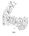
- the deck shown in Fig. 1 constitutes practically the entire mechanical section of a magnetic-tape apparatus for recording/reproducing signals on/from a magnetic tape 4 which is movable between two reels 2 and 3 of a magnetic-tape cassette 1. Those parts of the magnetic-tape cassette which are important for the description of the operating principle of the invention are shown in dash-dot lines.
- the magnetic tape is shown in full lines.
- the tape deck is suitable for transport of the magnetic tape between the reels in two opposite transport directions 5A and 5B.
- the deck comprises a chassis or deck plate 6 on which reel supports in the form of two reel discs 7 and 8 for the reels 2 and 3, respectively, are mounted for rotation.
- the deck plate 6 carries a rotary scanning system 9 around which the magnetic tape 4 is wrapped along a helical path through an angle of approximately 220 0 .
- the scanning system comprises a rotary upper drum 10 carrying two magnetic heads, not shown, which can record or read oblique parallel tracks across the width of the magnetic tape in known manner.
- Such rotary scanning systems are employed on a large scale in magnetic video tape recorders and for this reason the scanning system and other parts which are not relevant to the present invention will not be described in more detail.
- a threading mechanism of a known type which comprises an externally toothed threading ring 11 which is mounted for rotation on the deck plate.
- some elements of the threading mechanism which can pivot separately are shown, such as the gear segment 12 and the levers 13, 14 and 15.
- a number of guide elements bearing the reference numerals 16 to 23.
- a capstan 24 and a pressure roller 25 which presses the magnetic tape against the capstan.
- these tap- guide elements and the pressure roller are situated behind the magnetic tape via an opening in the cassette. The positions of the tape-guide elements and the pressure roller in this starting condition are shown in broken lines.
- a motor 26 which drives the ring 11 via a pinion 27 and the gear wheels 28 and 29.
- the outer teeth of the ring 11 co-operate with the teeth of the segment 12 and via an idler wheel 30 also with the teeth of a gear segment 3 which is connected to the lever 14.
- the lever 13 also is pivoted by the rotation of the threading ring 11, but the manner in which this is done is not shown for the sake of clarity.
- the magnetic tape is threaded as follows: the motor 26 is energized and the threading ring 11 is rotated anti-clockwise via the gear train 27-28-29.
- the gear segment 12 pivots the tape-guide element 23 and at the same time the levers 13 and 14 are pivoted in a similar way, thereby causing the tape-guide elements 16 and 17 to be pivoted.
- the tape-guide elements on the threading ring 11 now thread the magnetic tape in a loop around the scanning system 9.
- the lever 15 then performs a swing-out movement relative to the threading ring through co-operation with a guide 32 on the deck plate 6, so that the tape-guide element 22 assumes an end position which is defined by a stop 33 on the deck plate.
- the pressure roller 25 is mounted in a double lever 34 which is pivotable about the centre of the tape-guide element 21 and is urged into the operating position by a pressure lever 36 which is loaded by a spring 35.
- a gear wheel 43 which drives a gear wheel 44 which co-operates either with a gear wheel 45 on the reel 2 or with a gear wheel 46 on the reel 3, depending on the direction of rotation of the motor 40.
- the mechanism necessary for pivoting the gear wheel 44 from the gear wheel 45 to the gear wheel 46 or the other way round is not shown in Fig. 1 bit in principle it may be of a type as will be described hereinafter with reference to Fig. 4.
- a tape-pull control device which controls the tape pull in the part of the magnetic tape between the two tape-guide elements 16 and 17.
- the tape-pull control device comprises a two-armed sensing lever 49 having a first end 50A and a second end 50B and which is pivotable about a spindle 48 on the deck plate 1 in a first pivoting direction 47A and an opposite second pivoting direction 47B.
- Spring means in the form of a helical tension spring 51 which is pre-tensioned between the sensing lever and a pin 52 on the deck plate 6 act on the sensing lever.
- the tension spring 51 urges the sensing lever in the first pivoting direction 47A.
- tape-contact means in the form of a tape-guide pin 53 which, when a tape is present, is in contact with the part of the magnetic tape between the tape-guide elements 16 and 17.
- the reel disc 7 carries a brake disc which in the embodiment shown in Fig. 1 is integral with a gear wheel, for which reason the combination of the brake disc and the gear wheel bears the reference numeral 45.
- brake disc also refers to similar brake members which are not truly disc-shaped. It is essential only that there is a cylindrical braking surface. This surface may be, for example, a surface of a brake drum or a shaft.
- An elongate flexible braking member 54 which in the present embodiment comprises a brake band, is arranged around at least a part of the circumference of the brake disc 45.
- a brake band it is possible to use a brake cord, a brake wire or any other suitable flexible braking member.
- a first end 55A of the brake band is secured to the deck plate and the sensing lever 49 is co-operable with the brake band to produce a pulling force in the band which depends on the position of the sensing lever about the spindle, in order to obtain a braking torque between the brake disc 45 and the brake band as a function of the tape pull in the magnetic tape 4.
- the second end 55B of the brake band 54 is also secured to the deck plate 6.
- the sensing lever 49 co-operates with the brake band 54 at a point which is situated between the brake disc 45 and the second end 55B of the band and exerts a force F (Fig. 2) on the brake band which is directed transversely of this band.
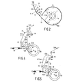
- Fig. 2 The effect of the invention will be illustrated by means of Fig. 2.
- the brake band 54 embraces the brake disc 45 over an angle 'f which extends from a point P where, proceeding from the first end 55A of the brake band to the second end 55B, the contact between the brake band and the brake disc 45 begins to a point Q where the contact ends.
- M is the frictional torque in Newton meters at the circumference of the brake disc
- S is the tensile force in Newton in the part of the brake band between point Q and the second end 55B of the band
- R is the radius in meters of the brake disc
- e is the base of the natural logarithm
- / u is the coefficient of friction between the brake band and the brake disc
- ⁇ is the wrapping angle in radians between pints P and Q.
- the dimensions of the brake disc are dictated by aspects of constructional engineering in combination with the dimensions of the cassette and the other parts of the tape deck.
- the angle r can be enlarged by wrapping the braking member several times around the brake disc, which gives rise to constructional problems in the case of a brake band but which is possible in the case of a brake cord.
- the brake band is wrapped around the brake disc in such a way that the part of the band between the brake disc and the second end 55B of the brake band almost contacts the first end 55A, the brake band being situated entirely in the plane of rotation of the brake disc 45.
- the magnitude of the coefficient of friction between the brake band and the brake disc depends on the materials used and is therefore dictated by the choice of these materials.
- the invention in particular aims at increasing the ratio between the tensile force S in the brake band and the transverse force F exerted on the brake band 54 by the sensing lever 49.
- the pivotal spindle 48 of the lever 49 is situated between the first end 50A and the second end 50B of this lever.
- first pressure means 57 in the form of a pressure nose which is integral with the sensing lever. Via this pressure nose direct pressure can be exerted on the brake band 54 in a first pressing direction 58 when the sensing lever is pivoted in its first pivoting direction 47A.
- the pressure nose 57 exerts a transverse force F on the part of the brake band between the brake disc 45 and the second end 55B of the band.
- the reactive force R is the resultant of the two opposed tensile forces S which occur in this section of the brake band.
- the forces S increase as the angle 0 ⁇ .. between the two parts of the brake band on each side of the pressure nose 57 decreases, enabling a substantial value of the quotient S:F to be obtained by a suitable choice of the angleOL.
- Fig. 3 the reel discs bear the reference numerals 62 and 63 and the magnetic tape is referenced 60.
- the first transport direction of the magnetic tape is 61A and the second transport direction is 61B.
- levers 64 and 65 whose ends carry tape-guide elements 66 and 67 .
- the sensing lever 68 is again a two-armed lever with a first end 69A and a second end 69B and between these ends it is pivotally mounted by means of a pivot 70.
- a tension spring 71 urges the sensing lever in its first pivoting direction 72A.
- the first end 69A of the sensing lever 68 carries tape-contact means in the form of a contact roller 73, which is in contact with that part of the magnetic tape which is situated between the two tape-guide elements 66 and 67.
- the braking member is again a brake band 74 having a first end 75A and a secnd end 75B.
- the reel 62 rotates in a direction 76A.
- the sensing lever 68 is in the position shown in full lines in the case of transport of the magnetic tape in the first transport direction.
- the sensing lever comprises first pressure means in the form of a pressure nose 77A at or near its second end 69B for a directly exerting pressure on the brake band 74 when the sensing lever is pivoted in its first pivoting direction 72A.
- the sensing lever shown in Fig. 3 also comprises second pressure means in the form of a second pressure nose 77B at or near its second end 69B to exert pressure on the braking member in a second pressing direction 78B opposite to the direction 78A when the sensing lever is pivoted in the second pivoting direction 72B.
- the second pressure nose 77B co-operates with the brake band 74 in the case of transport of the magnetic tape in the second transport direction 61B during recording or reproduction of signals on/from the magnetic tape.
- the sensing lever 68 is then in the position shown in dash-dot lines, in which it has been pivoted slightly in the second pivoting direction.
- the position of the brake band between the reel disc 62 and the second end 75B of the brake band in this situation is indicated by a broken line.
- the reel disc 62 rotates in its second direction of rotation 76B. It will be evident that in this situation an entirely different braking characteristic is obtained.
- FIG. 4 and 5 another embodiment of the invention as shown in Figs. 4 and 5 may be used.
- the magnetic tape 80 is shown in dash-dot lines.
- the sensing lever 81 again comprises two arms and is pivotable about a pin 82 between the first and second ends 83A and 83B of the lever.
- the first end 83B carries a guide roller 84 which co-operates with the magnetic tape at a point between two guide rollers 85 and 86 which correspond to the tape-guide elements 16 and 17 in Fig. 1.
- a tension spring 88 urges the sensing lever 81 in the first pivoting direction 87A.
- the reel disc 89 carries a brake disc 90 around which a braking member in the form of a brake cord or a brake band 91 is arranged.
- the braking member is secured at its first end 92A and its second end 92B.
- the sensing lever comprises first pressure means 93A for co-operation with the braking member 91 at a point which is located between the first end 92A of the braking member and the brake disc 90 (Fig. 4), and second pressure means 93B for co-operation with the braking member at a point which is situated between the second end 92B of the braking member and the brake disc 90 (Fig. 5).
- FIG. 4 shows the situation in which recording or reproducing is effected during transport of the magnetic tape 80 in the first transport direction 94A. This corresponds to a first direction of rotation 95A of the braking drum.
- Fig. 5 shows the situation in which during recording or reproduction the magnetic tape is moved in the second transport direction 94B, which corresponds to a direction of rotation 96B of the brake disc.
- Fig. 3 shows a part of a transmission device 59 by means of which only the upstream reel is driven in each of the two transport directions 61A and 61B.
- Driving is effected by means of a single winding motor, such as the motor 40 in Fig. 1.
- the winding motor drives a gear wheel 96.
- This gear wheel is rotatable about a stationary spindle 97 about which a member 98 is pivotable.
- This member comprises three limbs 99 to 101.
- the _imb 100 carries a pin 102 about which a gear wheel 103 which is in constant mesh with the gear wheel 96, is rotatable.
- gear wheel 103 meshes with a gear wheel 104 on the reel disc 63 and drives this gear wheel in a direction of rotation 105 corresponding to the first transport direction 61A of the magnetic tape 60.
- gear wheel 103 meshes with a gear wheel 106 onthe spindle 62 and drives this wheel in the second direction of rotation 76B which corresponds to the second transport direction 61B of the magnetic tape.
- the gear wheel 103 is set from its first position to its second position by reversing the direction of rotation of the winding motor.
- the reactive forces between teeth of the gear wheels 103 and 104 will produce an initial pivotal movement of the member 98.
- two coaxial auxiliary gear wheels 107 and 108 which are mounted for rotation about a pin 109 on the limb 101 of the member 98.
- the gear wheel 107 is constantly in mesh with the gear wheel 96 and rotates freely and consequently has no function in the first and in the second position of the member 98.
- a small initial pivotal movement of the member 98 results in the gear wheel 108 meshing with the gear segment 110 which is rigidly mounted on the deck plate.
- the member 98 is pivoted further by the motor torque which is transmitted to the gear segment 110 via the gear wheels 96, 107 and 108. This ensures a rapid and reliable change-over.
- the gear wheel 108 and the gear segment 110 are again disengaged, so that the drive of the magnetic tape 60 in the second transport direction 61B is not obstructed.
- the transmission device is coupled to the sensing lever 68.
- Coupling is effected by means of a coupling lever 111, a two-armed lever 112 and pivots 113, 114 which connect the levers pivotally to each other.
- the lever 112 is pivotable about a stationary pin 115.
- the end 116 of the lever 112 can transmit pressure to a protection 117 on the sensing lever 68.
- the transmission device 59 is set from the first position to the second position the end 116 is urged against the pressure nose 117, thereby moving the sensing lever in the second pivoting direction 72B. As a result of this, this lever can assume a position between the first and the second position.
- the first end 75A of the braking member is secured eccentrically to a rotatable adjusting element 118 which is formed with an eccentric screwdriver slit 119.
- the tape-pull sensing lever does not pull on an end of the braking member.
- the braking member is secured at both its ends to other parts of the apparatus and the sensing lever exerts a transverse force on the braking member at a point between the brake disc and an end of the braking member.
- a tensile force may be produced in the braking member which is several times greater than the transverse force exerted by the sensing lever.
Abstract
Description
- The invention relates to a magnetic-tape apparatus for recording/reproducing signals on/from a magnetic tape which is movable between two reels in a first transport direction and in an opposite second transport direction, comprising:
- a chassis; a rotatable reel support for each of the two reels; and a tape-pull control device for controlling the tape pull in the part of the magnetic tape between the two reels, which device comprises:
- a sensing lever which is mounted on the chassis so as to be pivotable about a pivot of axis in a first pivoting direction and in an opposite second pivoting direction and which has a first end and a second end; resilient means which act on the sensing lever to urge it in the first pivoting direction; tape-contact means near the first end of the sensing lever, which means when a tape is present, are in contact with the part of the magnetic tape which extends between the reels; a brake disc on one of the two reel supports and an elongate flexible braking member which surrounds at least a part of circumference of the brake disc and which has a first end which is secured to a part of the apparatus other than the securing lever, and a second end, which braking member co-operates with the sensing lever to produce a tensile force in the braking member depending on the position of the sensing lever about its pivotal axis and thereby influence the braking torque between the brake disc and the braking member as a function of the tape pull in the magnetic tape.
- German Patent Specification no. 1,549,107 describes such a magnetic-tape apparatus in which the braking member is a brake band. In this known apparatus the tape pull for each of the two tape reels is controlled by means of an associated tape-pull control device. Recording or reproducing of signals on the magnetic tape is effected only during transport of the magnetic tape in one of the two directions of transport. Each of the two tape-pull control devices comprises resilient means in the form of a tension spring which pulls on the free second end of the relevant brake band. The sensing levers also co-operate with these free secondends to vary the braking torque.
- It is favourable for a tape-pull control device if a given displacement of the sensing lever results in a comparatively large variation of the braking torque. Moreover, it is desirable that the tape-contact means of the sensing lever exert only a small force on the magnetic tape. In other words, it is desirable that small variations in the position of the magnetic tape and small variations in the force exerted on the magnetic tape by the sensing lever result in large variations of the braking torque. It is known that in the case of a flexible braking member such as a brake wire, a brake cord or a brake band, which co-operates with a brake disc, the frictional force exerted on the brake disc by the braking member increases exponentially in the direction of rotation of the brake disc. Therefore, it is favourable if the frictional force exerted on the braking member by the brake disc decreases towards the point where the sensing lever co-operates with the braking member. In the known magnetic-tape apparatus this is the case in the "playback" mode.
- It is the object of the invention to increase the variations in braking force as a result of variations in the position of the sensing lever for given dimensions of the lever and the invention is characterized in that also the second end of the braking member is a part of the apparatus other than the sensing lever secured to and the sensing lever is co-operable with the braking member at a point which is situated between the brake disc and an end of the braking member so as to exert a force on the braking member transversely of the longitudinal direction thereof.
- Particularly when the part of the braking member between the brake disc and the second end is nearly taut only a small transverse force is necessary to produce a comparatively large force in the longitudinal direction of the braking member. Indeed, the braking member is flexible and therefore it cannot take up compressive forces, so that the reactive force must be provided by only the tensile forces in the braking member. However, these forces act substantially perpendicularly to the applied transverse force and therefore they yield only a small component which counteracts the transverse force. In this way it is possible to produce tensile forces in the braking member which are several times, for example six times, as large as the transverse force exerted by the sensing lever. Another advantage is that the lever pivot is not loaded by the large tensile forces in the braking member but is subjected only to the small forces exerted on the sensing lever. The tensile forces in the braking member are taken up by the points of attachment to the chassis and the supporting means of the spindle. A small load on the pivot of the sensing lever is favourable for the sensitivity of the sensing lever to variations in pull in the magnetic tape. In other words, the mechanical hysteresis in the pivot of the sensing lever is minimal. Further advantages are obtained with respect to the mounting of the tape-pull control device. Indeed, the braking member need no longer be connected to a moving part of the apparatus.
- It is advantageous to employ an embodiment of the invention which is characterized in that the pivotal axis of the sensing lever is situated between the first end and the second end of said lever and the sensing lever is provided with first pressure means at or near its second end for exerting direct messure on the braking member in a first pressing direction when the sensing lever is pivoted in its first pivoting direction. This embodiment has the advantage that it requires a small number of parts and that the sensing lever can be mounted easily. Indeed, the sensing lever is separated entirely from the braking member and may be mounted or removed subsequently without affecting the mounting of the braking member.
- Another embodiment of the invention has the advantage that the tape-pull control device may also be used for the transport of the magnetic tape in the second transport direction. This is important for magnetic-tape apparatus with which signals can be recorded on or reproduced from the magnetic tape in each of the two directions of tape transport. This embodiment is characterized in that at or near its end the sensing lever carries second pressure means for exerting pressure on the braking member in a second pressing direction opposite to the first pressing direction when the sensing lever is pivoted in the second pivoting direction. It is also possible to use an embodiment which is characterized in that the first pressure means and co-operable with the braking member at a point which is situated between the first end of this member and the brake disc, and the second pressure means and co-operable with the braking member at a point which is situated between the second end of this member and the brake disc. In the last-mentioned case another braking characteristic is obtained, which will be discussed in more detail hereinafter.
- In many modern magnetic-tape apparatus in each of the two directions of transport of the magnetic tape, for reasons of economy, only the "upstream" reel is driven. Only a single drive motor is provided which drives only the upstream reel via a transmission device which can be moved between a first position for transport of the magnetic tape in the first transport direction and a second position for transport of the magnetic tape in the second transport direction. Generally, the transmission device comprises a pivotal support or other member which is pivoted from one side to the other side when the direction of rotation of the motor is reversed. As a result of this, a drive wheel which is mounted on the pivotal member and which is driven by the motor is pivoted from one reel to the other.
- In magnetic-tape apparatus of this kind problems may arise when the direction of transport of the magnetic tape is reversed. If at this instant the magnetic tape is not taut, the sensing lever will be in a position in which the braking member exerts the maximum braking torque. Preferably, this maximum braking torque is larger than the maximum driving torque that can be produced by the motor. This is important in order to ensure that the tape-pull control device will operate correctly in all cases in which magnetic-tape transport in the second direction is effected. However, if the brake is fully activated the motor will not be capable of moving the new "upstream" reel in the second transport direction. In view of this problem a further embodiment of the invention is of interest which is characterized in that the said transmission device is coupled to the sensing lever and moves this lever in the second pivoting direction when the transmission device moves from the first position to the second position so as to disengage the braking member from the circumference of the brake disc. After driving of the new upstream reel in the second transport direction has commenced the magnetic tape will be pulled taut and the tape-pull control device can revert to normal operation.
- Variations in length of the braking member arising during manufacture may give rise to variations in the position of the braking lever. This is undesirable, in particular if tape transport in the second transport direction is required, as is necessary to minimize the variations in the various parameters which affect the pulling force of the magnetic tape in the case of a reversal of the transport direction. An embodiment of the invention which is advantageous in this respect and which, in principle, may be combined with any one of the preceding embodiments is characterized in that at least one of the two ends of the braking member is adjustable in the longitudinal direction of this member.
- Some embodiments of the invention will now be described in more detail, by way of example, with reference to the accompanying drawings, in which:
- Fig. 1 is a schematic plan view of a video recorder deck which co-operates with a magnetic-tape cassette,
- Fig. 2 shows a part of Fig. 1 to an enlarged scale and represents some forces resolved into their components,
- Fig. 3 shows another version of a tape-pull control device, and
- Figs. 4 and 5 show in detail in two different positions a tape-pull control device intended for use in a deck as shown in Fig. 1.
- The deck shown in Fig. 1 constitutes practically the entire mechanical section of a magnetic-tape apparatus for recording/reproducing signals on/from a magnetic tape 4 which is movable between two
reels 2 and 3 of a magnetic-tape cassette 1. Those parts of the magnetic-tape cassette which are important for the description of the operating principle of the invention are shown in dash-dot lines. The magnetic tape is shown in full lines. The tape deck is suitable for transport of the magnetic tape between the reels in twoopposite transport directions - The deck comprises a chassis or deck plate 6 on which reel supports in the form of two
reel discs 7 and 8 for thereels 2 and 3, respectively, are mounted for rotation. - The deck plate 6 carries a
rotary scanning system 9 around which the magnetic tape 4 is wrapped along a helical path through an angle of approximately 2200. The scanning system comprises a rotaryupper drum 10 carrying two magnetic heads, not shown, which can record or read oblique parallel tracks across the width of the magnetic tape in known manner. Such rotary scanning systems are employed on a large scale in magnetic video tape recorders and for this reason the scanning system and other parts which are not relevant to the present invention will not be described in more detail. It is to be noted only that for threading the magnetic tape around thescanning system 9 there is provided a threading mechanism of a known type, which comprises an externallytoothed threading ring 11 which is mounted for rotation on the deck plate. Further, some elements of the threading mechanism which can pivot separately are shown, such as thegear segment 12 and thelevers reference numerals 16 to 23. For driving the magnetic tape there is provided acapstan 24 and apressure roller 25 which presses the magnetic tape against the capstan. In the non-threaded situation these tap- guide elements and the pressure roller are situated behind the magnetic tape via an opening in the cassette. The positions of the tape-guide elements and the pressure roller in this starting condition are shown in broken lines. - For the purpose of threading there is provided a
motor 26 which drives thering 11 via apinion 27 and thegear wheels 28 and 29. The outer teeth of thering 11 co-operate with the teeth of thesegment 12 and via anidler wheel 30 also with the teeth of a gear segment 3 which is connected to thelever 14. The lever 13 also is pivoted by the rotation of thethreading ring 11, but the manner in which this is done is not shown for the sake of clarity. - The magnetic tape is threaded as follows: the
motor 26 is energized and thethreading ring 11 is rotated anti-clockwise via the gear train 27-28-29. Thegear segment 12 pivots the tape-guide element 23 and at the same time thelevers 13 and 14 are pivoted in a similar way, thereby causing the tape-guide elements threading ring 11 now thread the magnetic tape in a loop around thescanning system 9. Thelever 15 then performs a swing-out movement relative to the threading ring through co-operation with aguide 32 on the deck plate 6, so that the tape-guide element 22 assumes an end position which is defined by a stop 33 on the deck plate. Thepressure roller 25 is mounted in adouble lever 34 which is pivotable about the centre of the tape-guide element 21 and is urged into the operating position by apressure lever 36 which is loaded by aspring 35. - For driving the
capstan 24 there is provided anotherelectric motor 37 which drives apulley 39 on thecapstan 24 via abelt 38. Thereels 2 and 3 are driven by an electric motor 40. This motor drives awheel 41 via abelt 42. Thewheel 41 carries agear wheel 43 which drives agear wheel 44 which co-operates either with agear wheel 45 on thereel 2 or with agear wheel 46 on the reel 3, depending on the direction of rotation of the motor 40. The mechanism necessary for pivoting thegear wheel 44 from thegear wheel 45 to thegear wheel 46 or the other way round is not shown in Fig. 1 bit in principle it may be of a type as will be described hereinafter with reference to Fig. 4. - A tape-pull control device is provided which controls the tape pull in the part of the magnetic tape between the two tape-
guide elements armed sensing lever 49 having afirst end 50A and asecond end 50B and which is pivotable about aspindle 48 on the deck plate 1 in afirst pivoting direction 47A and an oppositesecond pivoting direction 47B. Spring means in the form of ahelical tension spring 51 which is pre-tensioned between the sensing lever and apin 52 on the deck plate 6 act on the sensing lever. Thetension spring 51 urges the sensing lever in thefirst pivoting direction 47A. At or near thefirst end 50A of thesensing lever 49 there are arranged tape-contact means in the form of a tape-guide pin 53 which, when a tape is present, is in contact with the part of the magnetic tape between the tape-guide elements reference numeral 45. In the present context the term "brake disc" also refers to similar brake members which are not truly disc-shaped. It is essential only that there is a cylindrical braking surface. This surface may be, for example, a surface of a brake drum or a shaft. - An elongate
flexible braking member 54, which in the present embodiment comprises a brake band, is arranged around at least a part of the circumference of thebrake disc 45. Instead of a brake band it is possible to use a brake cord, a brake wire or any other suitable flexible braking member. Afirst end 55A of the brake band is secured to the deck plate and thesensing lever 49 is co-operable with the brake band to produce a pulling force in the band which depends on the position of the sensing lever about the spindle, in order to obtain a braking torque between thebrake disc 45 and the brake band as a function of the tape pull in the magnetic tape 4. Thesecond end 55B of thebrake band 54 is also secured to the deck plate 6. Thesensing lever 49 co-operates with thebrake band 54 at a point which is situated between thebrake disc 45 and thesecond end 55B of the band and exerts a force F (Fig. 2) on the brake band which is directed transversely of this band. - The effect of the invention will be illustrated by means of Fig. 2. During transport of the magnetic tape in the
first transport direction 5A, see Fig. 1, thereel 2 rotates in thedirection 56A. Thebrake band 54 embraces thebrake disc 45 over an angle 'f which extends from a point P where, proceeding from thefirst end 55A of the brake band to thesecond end 55B, the contact between the brake band and thebrake disc 45 begins to a point Q where the contact ends. If a tensile force is exerted in thebrake band 54 the frictional torque between the brake band and thebrake disc 45 will be:
where M is the frictional torque in Newton meters at the circumference of the brake disc, S is the tensile force in Newton in the part of the brake band between point Q and thesecond end 55B of the band, R is the radius in meters of the brake disc, e is the base of the natural logarithm,/u is the coefficient of friction between the brake band and the brake disc, and ϕ is the wrapping angle in radians between pints P and Q. - For a large braking torque on the
brake disc 45 it is therefore necessary to aim at a large diameter of the brake disc, a large angle ϕ, a large coefficient of friction IU between the brake band and the brake disc, and a large tensile force S. The dimensions of the brake disc are dictated by aspects of constructional engineering in combination with the dimensions of the cassette and the other parts of the tape deck. The angle r can be enlarged by wrapping the braking member several times around the brake disc, which gives rise to constructional problems in the case of a brake band but which is possible in the case of a brake cord. In the present example the brake band is wrapped around the brake disc in such a way that the part of the band between the brake disc and thesecond end 55B of the brake band almost contacts thefirst end 55A, the brake band being situated entirely in the plane of rotation of thebrake disc 45. The magnitude of the coefficient of friction between the brake band and the brake disc depends on the materials used and is therefore dictated by the choice of these materials. - The invention in particular aims at increasing the ratio between the tensile force S in the brake band and the transverse force F exerted on the
brake band 54 by thesensing lever 49. Thepivotal spindle 48 of thelever 49 is situated between thefirst end 50A and thesecond end 50B of this lever. At or near the latter end there are arranged first pressure means 57 in the form of a pressure nose which is integral with the sensing lever. Via this pressure nose direct pressure can be exerted on thebrake band 54 in a firstpressing direction 58 when the sensing lever is pivoted in itsfirst pivoting direction 47A. Thus, thepressure nose 57 exerts a transverse force F on the part of the brake band between thebrake disc 45 and thesecond end 55B of the band. As is shown in Fig. 2 the reactive force R is the resultant of the two opposed tensile forces S which occur in this section of the brake band. The forces S increase as the angle 0<.. between the two parts of the brake band on each side of thepressure nose 57 decreases, enabling a substantial value of the quotient S:F to be obtained by a suitable choice of the angleOL. - In Fig. 3 the reel discs bear the
reference numerals levers 13 and 14 in Fig. 1 there are providedlevers guide elements sensing lever 68 is again a two-armed lever with afirst end 69A and asecond end 69B and between these ends it is pivotally mounted by means of apivot 70. Atension spring 71 urges the sensing lever in itsfirst pivoting direction 72A. Thefirst end 69A of thesensing lever 68 carries tape-contact means in the form of acontact roller 73, which is in contact with that part of the magnetic tape which is situated between the two tape-guide elements brake band 74 having afirst end 75A and asecnd end 75B. During transport of themagnetic tape 60 in thefirst transport direction 61A thereel 62 rotates in adirection 76A. Thesensing lever 68 is in the position shown in full lines in the case of transport of the magnetic tape in the first transport direction. Again the sensing lever comprises first pressure means in the form of apressure nose 77A at or near itssecond end 69B for a directly exerting pressure on thebrake band 74 when the sensing lever is pivoted in itsfirst pivoting direction 72A. In contradistinction to the sensing lever shown in Fig. 1 the sensing lever shown in Fig. 3 also comprises second pressure means in the form of asecond pressure nose 77B at or near itssecond end 69B to exert pressure on the braking member in a secondpressing direction 78B opposite to thedirection 78A when the sensing lever is pivoted in thesecond pivoting direction 72B. Thesecond pressure nose 77B co-operates with thebrake band 74 in the case of transport of the magnetic tape in thesecond transport direction 61B during recording or reproduction of signals on/from the magnetic tape. Thesensing lever 68 is then in the position shown in dash-dot lines, in which it has been pivoted slightly in the second pivoting direction. The position of the brake band between thereel disc 62 and thesecond end 75B of the brake band in this situation is indicated by a broken line. Thereel disc 62 rotates in its second direction ofrotation 76B. It will be evident that in this situation an entirely different braking characteristic is obtained. Owing to the pivotal movement of thesensing lever 68 in thesecond pivoting direction 72B thetension spring 71 has been extended to a certain extent, so that the pull in themagnetic tape 60 will be slightly larger, although in practice this may be minimal depending on the dimensioning of thetension spring 71. A more important difference is that thepressure nose 77B now co-operates with that part of thebrake band 74 which, in relation to the direction of rotation of the reel disc and in comparison with the preceding situation, is situated at the other side of thebrake disc 79. Variations in tensile force in the part of the brake band between thesecond end 75B hereof and thebraking drum 79 therefore now have less effect on the resulting braking torque. Generally this is regarded as an advantage because in the second transport direction the part of the magnetic tape with which the sensing lever co-operates is situated "downstream" of the scanning unit. The rotary drum of the scanning unit in fact also brakes the tape to some extent. In the second transport direction variations in tape pull therefore have a greater influence on the variation of the friction between the magnetic tape and the scanning system than in the first direction of transport of the magnetic tape. - However, if desired, another embodiment of the invention as shown in Figs. 4 and 5 may be used. In these Figures the
magnetic tape 80 is shown in dash-dot lines. Thesensing lever 81 again comprises two arms and is pivotable about apin 82 between the first and second ends 83A and 83B of the lever. Thefirst end 83B carries aguide roller 84 which co-operates with the magnetic tape at a point between twoguide rollers guide elements tension spring 88 urges thesensing lever 81 in thefirst pivoting direction 87A. Thereel disc 89 carries abrake disc 90 around which a braking member in the form of a brake cord or abrake band 91 is arranged. The braking member is secured at itsfirst end 92A and itssecond end 92B. At or near itssecond end 83B the sensing lever comprises first pressure means 93A for co-operation with the brakingmember 91 at a point which is located between thefirst end 92A of the braking member and the brake disc 90 (Fig. 4), and second pressure means 93B for co-operation with the braking member at a point which is situated between thesecond end 92B of the braking member and the brake disc 90 (Fig. 5). Fig. 4 shows the situation in which recording or reproducing is effected during transport of themagnetic tape 80 in thefirst transport direction 94A. This corresponds to a first direction ofrotation 95A of the braking drum. Fig. 5 shows the situation in which during recording or reproduction the magnetic tape is moved in thesecond transport direction 94B, which corresponds to a direction of rotation 96B of the brake disc. - Fig. 3 shows a part of a
transmission device 59 by means of which only the upstream reel is driven in each of the twotransport directions gear wheel 96. This gear wheel is rotatable about astationary spindle 97 about which amember 98 is pivotable. This member comprises threelimbs 99 to 101. The _imb 100 carries a pin 102 about which a gear wheel 103 which is in constant mesh with thegear wheel 96, is rotatable. In a first position shown in full lines the gear wheel 103 meshes with agear wheel 104 on thereel disc 63 and drives this gear wheel in a direction ofrotation 105 corresponding to thefirst transport direction 61A of themagnetic tape 60. In a second position shown in broken lines the gear wheel 103 meshes with agear wheel 106onthe spindle 62 and drives this wheel in the second direction ofrotation 76B which corresponds to thesecond transport direction 61B of the magnetic tape. - The gear wheel 103 is set from its first position to its second position by reversing the direction of rotation of the winding motor. The reactive forces between teeth of the
gear wheels 103 and 104 will produce an initial pivotal movement of themember 98. For a rapid and reliable pivotal movement there are further provided two coaxialauxiliary gear wheels pin 109 on thelimb 101 of themember 98. Thegear wheel 107 is constantly in mesh with thegear wheel 96 and rotates freely and consequently has no function in the first and in the second position of themember 98. However, a small initial pivotal movement of themember 98 results in thegear wheel 108 meshing with thegear segment 110 which is rigidly mounted on the deck plate. As a result of this, themember 98 is pivoted further by the motor torque which is transmitted to thegear segment 110 via thegear wheels gear wheel 108 and thegear segment 110 are again disengaged, so that the drive of themagnetic tape 60 in thesecond transport direction 61B is not obstructed. - By means of the
limb 99 the transmission device is coupled to thesensing lever 68. Coupling is effected by means of acoupling lever 111, a two-armed lever 112 and pivots 113, 114 which connect the levers pivotally to each other. Thelever 112 is pivotable about astationary pin 115. Theend 116 of thelever 112 can transmit pressure to aprotection 117 on thesensing lever 68. When thetransmission device 59 is set from the first position to the second position theend 116 is urged against thepressure nose 117, thereby moving the sensing lever in thesecond pivoting direction 72B. As a result of this, this lever can assume a position between the first and the second position. In this intermediate position neither thepressure nose 77A nor thepressure nose 77B co-operate with the brakingmember 74, so that this member is clear of the circumference of the brake disc. Thus, when the tape 61 is somewhat slack during reversal of the transport direction thetension spring 71 will not prevent the winding motor from driving thespindle 62 in itssecond transport direction 76B. Once driving takes place the magnetic tape is pulled taut between thetape guide elements - The
first end 75A of the braking member is secured eccentrically to arotatable adjusting element 118 which is formed with an eccentric screwdriver slit 119. By rotating the adjustingelement 118 the desired position of thesensing lever 68 can be adjusted simply, regardless of dimensional and manufacturing tolerances of the various parts of the tape-pull control device. - Within the framework of the invention many alternative enibodi- ments may be designed, the main feature of the invention being that the tape-pull sensing lever does not pull on an end of the braking member. Instead, the braking member is secured at both its ends to other parts of the apparatus and the sensing lever exerts a transverse force on the braking member at a point between the brake disc and an end of the braking member. Thus a tensile force may be produced in the braking member which is several times greater than the transverse force exerted by the sensing lever.
Claims (6)
characterized in that
Applications Claiming Priority (2)
| Application Number | Priority Date | Filing Date | Title |
|---|---|---|---|
| NL8403472 | 1984-11-14 | ||
| NL8403472A NL8403472A (en) | 1984-11-14 | 1984-11-14 | MAGNETIC TAPE DEVICE. |
Publications (2)
| Publication Number | Publication Date |
|---|---|
| EP0182419A1 true EP0182419A1 (en) | 1986-05-28 |
| EP0182419B1 EP0182419B1 (en) | 1989-05-31 |
Family
ID=19844763
Family Applications (1)
| Application Number | Title | Priority Date | Filing Date |
|---|---|---|---|
| EP85201798A Expired EP0182419B1 (en) | 1984-11-14 | 1985-11-06 | Magnetic-tape apparatus |
Country Status (10)
| Country | Link |
|---|---|
| US (1) | US4614315A (en) |
| EP (1) | EP0182419B1 (en) |
| JP (1) | JPH0521714Y2 (en) |
| KR (1) | KR940007423B1 (en) |
| CS (1) | CS816385A2 (en) |
| DE (1) | DE3570788D1 (en) |
| HK (1) | HK88091A (en) |
| HU (1) | HU193832B (en) |
| NL (1) | NL8403472A (en) |
| SG (1) | SG86390G (en) |
Cited By (4)
| Publication number | Priority date | Publication date | Assignee | Title |
|---|---|---|---|---|
| EP0227917A2 (en) * | 1985-11-13 | 1987-07-08 | Hitachi, Ltd. | A tape tension controller for a cassette recording/playback apparatus |
| EP0396018A2 (en) * | 1989-04-29 | 1990-11-07 | SANYO ELECTRIC Co., Ltd. | Magnetic tape back tension device for magnetic recording-reproduction system |
| EP0867875A2 (en) * | 1997-03-28 | 1998-09-30 | SANYO ELECTRIC Co., Ltd. | Tape tensioner for use in magnetic recording-playback device |
| WO1999050846A1 (en) * | 1998-03-27 | 1999-10-07 | Koninklijke Philips Electronics N.V. | Device having tension control means including a coil spring for controlling the tension in an elongate material |
Families Citing this family (12)
| Publication number | Priority date | Publication date | Assignee | Title |
|---|---|---|---|---|
| JPS59171069A (en) * | 1983-03-18 | 1984-09-27 | Sony Corp | Magnetic recording and reproducing device |
| DE3784269T2 (en) * | 1986-05-27 | 1993-06-09 | Hitachi Ltd | DRUM WITH ROTATING MAGNETIC HEADS FOR RECORDING AND PLAYBACK DEVICE. |
| JP2661084B2 (en) * | 1987-12-28 | 1997-10-08 | 松下電器産業株式会社 | Tape tension control device |
| US5184259A (en) * | 1988-07-05 | 1993-02-02 | U.S. Philips Corporation | Helical-scan magnetic tape apparatus having a tape-transport path with twisting path-sections for tape-path correction |
| KR920000922Y1 (en) * | 1989-05-31 | 1992-01-31 | 삼성전자 주식회사 | Pincushion control circuit |
| JP2656618B2 (en) * | 1989-06-14 | 1997-09-24 | 株式会社日立製作所 | Magnetic recording / reproducing device |
| US5140475A (en) * | 1989-12-14 | 1992-08-18 | Tanashin Denki Co., Ltd. | Tape recorder with automatic pre-reproduction tape slack eliminating function |
| US5335877A (en) * | 1991-07-10 | 1994-08-09 | Funai Electric Co., Ltd. | Device for exchanging a tape drive mode |
| US5460334A (en) * | 1993-02-06 | 1995-10-24 | Goldstar Co., Ltd. | Tape tension control apparatus for video cassette recorder |
| JPH06251457A (en) * | 1993-02-26 | 1994-09-09 | Samsung Electron Co Ltd | Running device for tape recorder |
| KR19990032099A (en) * | 1997-10-16 | 1999-05-06 | 신사쿠 다나카 | Disc loading device of disc player |
| JP2002367256A (en) * | 2001-06-04 | 2002-12-20 | Matsushita Electric Ind Co Ltd | Tape tension control mechanism for magnetic recording and reproducing device |
Citations (11)
| Publication number | Priority date | Publication date | Assignee | Title |
|---|---|---|---|---|
| FR1024985A (en) * | 1950-07-12 | 1953-04-09 | Self-tightening brake device for sound recording machines on wire or magnetic tape | |
| GB938421A (en) * | 1959-04-18 | 1963-10-02 | Emi Ltd | Improvements in or relating to web transporting apparatus |
| GB940613A (en) * | 1961-05-11 | 1963-10-30 | Ampex | Improvements in or relating to tape feeding apparatus |
| DE1549107A1 (en) * | 1967-11-21 | 1970-10-22 | Telefunken Patent | Device for magnetic tape devices to keep the tape tension constant |
| US3539129A (en) * | 1967-04-24 | 1970-11-10 | Philips Corp | Tape tension adjusting appratus |
| FR2389194A1 (en) * | 1977-04-26 | 1978-11-24 | Philips Nv | RECORDING AND / OR READING DEVICE |
| DE3127592A1 (en) * | 1980-07-14 | 1982-04-01 | Canon K.K., Tokyo | Cassette apparatus for magnetic recording and/or playback |
| EP0057921A2 (en) * | 1981-02-06 | 1982-08-18 | Matsushita Electric Industrial Co., Ltd. | Magnetic recording/playback device |
| US4345725A (en) * | 1979-06-18 | 1982-08-24 | Olympus Optical Co., Ltd. | Braking mechanism of a tape recorder |
| GB2094542A (en) * | 1981-02-16 | 1982-09-15 | Tokyo Shibaura Electric Co | Video tape recorder |
| DE3230001A1 (en) * | 1981-08-13 | 1983-03-03 | Victor Company Of Japan, Ltd., Yokohama, Kanagawa | VIDEO SIGNAL RECORDING AND PLAYING DEVICE |
Family Cites Families (5)
| Publication number | Priority date | Publication date | Assignee | Title |
|---|---|---|---|---|
| US3580525A (en) * | 1967-11-21 | 1971-05-25 | Telefunken Patent | Arrangement maintaining constant tape tension in magnetic tape recorders |
| JPS5246688B2 (en) * | 1972-11-07 | 1977-11-26 | ||
| US4074873A (en) * | 1975-12-10 | 1978-02-21 | Nippon Columbia Kabushikikaisha | Tension servo apparatus |
| JPS5815854B2 (en) * | 1977-04-19 | 1983-03-28 | 日本ビクター株式会社 | tape drive device |
| US4437738A (en) * | 1980-04-18 | 1984-03-20 | Henry Frank Yoder, III | Optical rollfiche reader |
-
1984
- 1984-11-14 NL NL8403472A patent/NL8403472A/en not_active Application Discontinuation
-
1985
- 1985-02-26 US US06/705,753 patent/US4614315A/en not_active Expired - Fee Related
- 1985-11-06 DE DE8585201798T patent/DE3570788D1/en not_active Expired
- 1985-11-06 EP EP85201798A patent/EP0182419B1/en not_active Expired
- 1985-11-11 HU HU854295A patent/HU193832B/en unknown
- 1985-11-11 KR KR1019850008399A patent/KR940007423B1/en not_active IP Right Cessation
- 1985-11-12 JP JP1985173077U patent/JPH0521714Y2/ja not_active Expired - Lifetime
- 1985-11-13 CS CS858163A patent/CS816385A2/en unknown
-
1990
- 1990-10-24 SG SG863/90A patent/SG86390G/en unknown
-
1991
- 1991-11-07 HK HK880/91A patent/HK88091A/en unknown
Patent Citations (11)
| Publication number | Priority date | Publication date | Assignee | Title |
|---|---|---|---|---|
| FR1024985A (en) * | 1950-07-12 | 1953-04-09 | Self-tightening brake device for sound recording machines on wire or magnetic tape | |
| GB938421A (en) * | 1959-04-18 | 1963-10-02 | Emi Ltd | Improvements in or relating to web transporting apparatus |
| GB940613A (en) * | 1961-05-11 | 1963-10-30 | Ampex | Improvements in or relating to tape feeding apparatus |
| US3539129A (en) * | 1967-04-24 | 1970-11-10 | Philips Corp | Tape tension adjusting appratus |
| DE1549107A1 (en) * | 1967-11-21 | 1970-10-22 | Telefunken Patent | Device for magnetic tape devices to keep the tape tension constant |
| FR2389194A1 (en) * | 1977-04-26 | 1978-11-24 | Philips Nv | RECORDING AND / OR READING DEVICE |
| US4345725A (en) * | 1979-06-18 | 1982-08-24 | Olympus Optical Co., Ltd. | Braking mechanism of a tape recorder |
| DE3127592A1 (en) * | 1980-07-14 | 1982-04-01 | Canon K.K., Tokyo | Cassette apparatus for magnetic recording and/or playback |
| EP0057921A2 (en) * | 1981-02-06 | 1982-08-18 | Matsushita Electric Industrial Co., Ltd. | Magnetic recording/playback device |
| GB2094542A (en) * | 1981-02-16 | 1982-09-15 | Tokyo Shibaura Electric Co | Video tape recorder |
| DE3230001A1 (en) * | 1981-08-13 | 1983-03-03 | Victor Company Of Japan, Ltd., Yokohama, Kanagawa | VIDEO SIGNAL RECORDING AND PLAYING DEVICE |
Cited By (8)
| Publication number | Priority date | Publication date | Assignee | Title |
|---|---|---|---|---|
| EP0227917A2 (en) * | 1985-11-13 | 1987-07-08 | Hitachi, Ltd. | A tape tension controller for a cassette recording/playback apparatus |
| EP0227917A3 (en) * | 1985-11-13 | 1989-07-26 | Hitachi, Ltd. | A tape tension controller for a cassette recording/playback apparatus |
| EP0396018A2 (en) * | 1989-04-29 | 1990-11-07 | SANYO ELECTRIC Co., Ltd. | Magnetic tape back tension device for magnetic recording-reproduction system |
| EP0396018A3 (en) * | 1989-04-29 | 1992-03-11 | SANYO ELECTRIC Co., Ltd. | Magnetic tape back tension device for magnetic recording-reproduction system |
| EP0867875A2 (en) * | 1997-03-28 | 1998-09-30 | SANYO ELECTRIC Co., Ltd. | Tape tensioner for use in magnetic recording-playback device |
| EP0867875A3 (en) * | 1997-03-28 | 1999-07-21 | SANYO ELECTRIC Co., Ltd. | Tape tensioner for use in magnetic recording-playback device |
| WO1999050846A1 (en) * | 1998-03-27 | 1999-10-07 | Koninklijke Philips Electronics N.V. | Device having tension control means including a coil spring for controlling the tension in an elongate material |
| US6079658A (en) * | 1998-03-27 | 2000-06-27 | U.S. Philip Corporation | Device having tension control means including a coil spring for controlling the tension in an elongate material |
Also Published As
| Publication number | Publication date |
|---|---|
| EP0182419B1 (en) | 1989-05-31 |
| HK88091A (en) | 1991-11-15 |
| JPS6190045U (en) | 1986-06-11 |
| HU193832B (en) | 1987-12-28 |
| KR860004398A (en) | 1986-06-20 |
| JPH0521714Y2 (en) | 1993-06-03 |
| HUT39283A (en) | 1986-08-28 |
| CS816385A2 (en) | 1991-07-16 |
| KR940007423B1 (en) | 1994-08-18 |
| SG86390G (en) | 1991-01-04 |
| US4614315A (en) | 1986-09-30 |
| NL8403472A (en) | 1986-06-02 |
| DE3570788D1 (en) | 1989-07-06 |
Similar Documents
| Publication | Publication Date | Title |
|---|---|---|
| EP0182419B1 (en) | Magnetic-tape apparatus | |
| CA1096966A (en) | Video signal recording and/or reproducing apparatus | |
| EP0028928B1 (en) | A magnetic tape recording and/or reproducing apparatus | |
| US2868470A (en) | Magnetic tape apparatus | |
| JPS5815854B2 (en) | tape drive device | |
| US4310131A (en) | Braking mechanism, as for a tape recorder | |
| US3863853A (en) | Endless magnetic tape cartridge | |
| US3894702A (en) | Reel disc device in a recording and/or reproducing apparatus | |
| US5195697A (en) | Apparatus for preventing tape sag during mode changing in a video recorder | |
| KR920010839B1 (en) | Apparatus for stopping reel tape | |
| US5758835A (en) | Magnetic tape apparatus for controlling a back tension of a magnetic tape running on a rotary drum | |
| EP0372250A2 (en) | Magnetic recording/playback apparatus | |
| US6079658A (en) | Device having tension control means including a coil spring for controlling the tension in an elongate material | |
| US4470086A (en) | Record reproduction apparatus | |
| US3295780A (en) | Tape recording and reproducing apparatus | |
| US5992781A (en) | Indirect drive mechanism for recording and reproducing apparatus capable of accomodating different size cassettes | |
| US4196872A (en) | Tape transport apparatus with translative friction force system | |
| JP2667329B2 (en) | Tape reverse tension mechanism of magnetic recording / reproducing device | |
| US4359180A (en) | Cassette tape recorder | |
| KR930006582Y1 (en) | Apparatus for preventing tape loosing of tape recorder | |
| JP3346081B2 (en) | Recording and playback device | |
| JPH0746449B2 (en) | Magnetic recording / reproducing device | |
| JP2607724B2 (en) | Magnetic recording / reproducing device | |
| JP3430716B2 (en) | Recording and playback device | |
| KR100407302B1 (en) | A idler gear apparatus for VCR |
Legal Events
| Date | Code | Title | Description |
|---|---|---|---|
| PUAI | Public reference made under article 153(3) epc to a published international application that has entered the european phase |
Free format text: ORIGINAL CODE: 0009012 |
|
| AK | Designated contracting states |
Kind code of ref document: A1 Designated state(s): DE FR GB |
|
| 17P | Request for examination filed |
Effective date: 19861119 |
|
| 17Q | First examination report despatched |
Effective date: 19880708 |
|
| GRAA | (expected) grant |
Free format text: ORIGINAL CODE: 0009210 |
|
| AK | Designated contracting states |
Kind code of ref document: B1 Designated state(s): DE FR GB |
|
| REF | Corresponds to: |
Ref document number: 3570788 Country of ref document: DE Date of ref document: 19890706 |
|
| ET | Fr: translation filed | ||
| PLBE | No opposition filed within time limit |
Free format text: ORIGINAL CODE: 0009261 |
|
| STAA | Information on the status of an ep patent application or granted ep patent |
Free format text: STATUS: NO OPPOSITION FILED WITHIN TIME LIMIT |
|
| 26N | No opposition filed | ||
| PGFP | Annual fee paid to national office [announced via postgrant information from national office to epo] |
Ref country code: GB Payment date: 19901031 Year of fee payment: 6 |
|
| PGFP | Annual fee paid to national office [announced via postgrant information from national office to epo] |
Ref country code: FR Payment date: 19901123 Year of fee payment: 6 |
|
| PGFP | Annual fee paid to national office [announced via postgrant information from national office to epo] |
Ref country code: DE Payment date: 19910125 Year of fee payment: 6 |
|
| PG25 | Lapsed in a contracting state [announced via postgrant information from national office to epo] |
Ref country code: GB Effective date: 19911106 |
|
| GBPC | Gb: european patent ceased through non-payment of renewal fee | ||
| PG25 | Lapsed in a contracting state [announced via postgrant information from national office to epo] |
Ref country code: FR Effective date: 19920731 |
|
| PG25 | Lapsed in a contracting state [announced via postgrant information from national office to epo] |
Ref country code: DE Effective date: 19920801 |
|
| REG | Reference to a national code |
Ref country code: FR Ref legal event code: ST |