EP0182270A2 - Device for electrophotographically producing a print master - Google Patents
Device for electrophotographically producing a print master Download PDFInfo
- Publication number
- EP0182270A2 EP0182270A2 EP85114402A EP85114402A EP0182270A2 EP 0182270 A2 EP0182270 A2 EP 0182270A2 EP 85114402 A EP85114402 A EP 85114402A EP 85114402 A EP85114402 A EP 85114402A EP 0182270 A2 EP0182270 A2 EP 0182270A2
- Authority
- EP
- European Patent Office
- Prior art keywords
- plate
- flaps
- rows
- air nozzles
- exposure
- Prior art date
- Legal status (The legal status is an assumption and is not a legal conclusion. Google has not performed a legal analysis and makes no representation as to the accuracy of the status listed.)
- Withdrawn
Links
Images


Classifications
-
- G—PHYSICS
- G03—PHOTOGRAPHY; CINEMATOGRAPHY; ANALOGOUS TECHNIQUES USING WAVES OTHER THAN OPTICAL WAVES; ELECTROGRAPHY; HOLOGRAPHY
- G03G—ELECTROGRAPHY; ELECTROPHOTOGRAPHY; MAGNETOGRAPHY
- G03G15/00—Apparatus for electrographic processes using a charge pattern
- G03G15/65—Apparatus which relate to the handling of copy material
- G03G15/6529—Transporting
-
- B—PERFORMING OPERATIONS; TRANSPORTING
- B65—CONVEYING; PACKING; STORING; HANDLING THIN OR FILAMENTARY MATERIAL
- B65H—HANDLING THIN OR FILAMENTARY MATERIAL, e.g. SHEETS, WEBS, CABLES
- B65H3/00—Separating articles from piles
- B65H3/08—Separating articles from piles using pneumatic force
- B65H3/0808—Suction grippers
- B65H3/0816—Suction grippers separating from the top of pile
-
- B—PERFORMING OPERATIONS; TRANSPORTING
- B65—CONVEYING; PACKING; STORING; HANDLING THIN OR FILAMENTARY MATERIAL
- B65H—HANDLING THIN OR FILAMENTARY MATERIAL, e.g. SHEETS, WEBS, CABLES
- B65H5/00—Feeding articles separated from piles; Feeding articles to machines
- B65H5/22—Feeding articles separated from piles; Feeding articles to machines by air-blast or suction device
- B65H5/222—Feeding articles separated from piles; Feeding articles to machines by air-blast or suction device by suction devices
-
- G—PHYSICS
- G03—PHOTOGRAPHY; CINEMATOGRAPHY; ANALOGOUS TECHNIQUES USING WAVES OTHER THAN OPTICAL WAVES; ELECTROGRAPHY; HOLOGRAPHY
- G03G—ELECTROGRAPHY; ELECTROPHOTOGRAPHY; MAGNETOGRAPHY
- G03G15/00—Apparatus for electrographic processes using a charge pattern
- G03G15/65—Apparatus which relate to the handling of copy material
- G03G15/6597—Apparatus which relate to the handling of copy material the imaging being conformed directly on the copy material, e.g. using photosensitive copy material, dielectric copy material for electrostatic printing
-
- B—PERFORMING OPERATIONS; TRANSPORTING
- B65—CONVEYING; PACKING; STORING; HANDLING THIN OR FILAMENTARY MATERIAL
- B65H—HANDLING THIN OR FILAMENTARY MATERIAL, e.g. SHEETS, WEBS, CABLES
- B65H2701/00—Handled material; Storage means
- B65H2701/10—Handled articles or webs
- B65H2701/19—Specific article or web
- B65H2701/1928—Printing plate
-
- G—PHYSICS
- G03—PHOTOGRAPHY; CINEMATOGRAPHY; ANALOGOUS TECHNIQUES USING WAVES OTHER THAN OPTICAL WAVES; ELECTROGRAPHY; HOLOGRAPHY
- G03G—ELECTROGRAPHY; ELECTROPHOTOGRAPHY; MAGNETOGRAPHY
- G03G2215/00—Apparatus for electrophotographic processes
- G03G2215/00362—Apparatus for electrophotographic processes relating to the copy medium handling
- G03G2215/00367—The feeding path segment where particular handling of the copy medium occurs, segments being adjacent and non-overlapping. Each segment is identified by the most downstream point in the segment, so that for instance the segment labelled "Fixing device" is referring to the path between the "Transfer device" and the "Fixing device"
- G03G2215/00371—General use over the entire feeding path
-
- G—PHYSICS
- G03—PHOTOGRAPHY; CINEMATOGRAPHY; ANALOGOUS TECHNIQUES USING WAVES OTHER THAN OPTICAL WAVES; ELECTROGRAPHY; HOLOGRAPHY
- G03G—ELECTROGRAPHY; ELECTROPHOTOGRAPHY; MAGNETOGRAPHY
- G03G2215/00—Apparatus for electrophotographic processes
- G03G2215/00362—Apparatus for electrophotographic processes relating to the copy medium handling
- G03G2215/00367—The feeding path segment where particular handling of the copy medium occurs, segments being adjacent and non-overlapping. Each segment is identified by the most downstream point in the segment, so that for instance the segment labelled "Fixing device" is referring to the path between the "Transfer device" and the "Fixing device"
- G03G2215/00396—Pick-up device
-
- G—PHYSICS
- G03—PHOTOGRAPHY; CINEMATOGRAPHY; ANALOGOUS TECHNIQUES USING WAVES OTHER THAN OPTICAL WAVES; ELECTROGRAPHY; HOLOGRAPHY
- G03G—ELECTROGRAPHY; ELECTROPHOTOGRAPHY; MAGNETOGRAPHY
- G03G2215/00—Apparatus for electrophotographic processes
- G03G2215/00362—Apparatus for electrophotographic processes relating to the copy medium handling
- G03G2215/00443—Copy medium
- G03G2215/00518—Recording medium, e.g. photosensitive
-
- G—PHYSICS
- G03—PHOTOGRAPHY; CINEMATOGRAPHY; ANALOGOUS TECHNIQUES USING WAVES OTHER THAN OPTICAL WAVES; ELECTROGRAPHY; HOLOGRAPHY
- G03G—ELECTROGRAPHY; ELECTROPHOTOGRAPHY; MAGNETOGRAPHY
- G03G2215/00—Apparatus for electrophotographic processes
- G03G2215/00362—Apparatus for electrophotographic processes relating to the copy medium handling
- G03G2215/00443—Copy medium
- G03G2215/00523—Other special types, e.g. tabbed
Definitions
- the invention relates to a device for the electrophotographic production of printing forms which are stacked in the undelected state in a magazine and are individually removed from the magazine by means of suction elements and transported to a charging station in order to be moved from there to further processing stations of the device.
- the magazine is inclined to the vertical, the lifting cylinder in its receiving position being directed perpendicularly onto the uncoated side of the uppermost printing form and the bowl-shaped plate running parallel to the uncoated side of the printing form and onto this for lifting off the top plate is lowered from the stack until the suction elements sit on the printing form.
- DE-PS 24 62 216 describes a device for the electrophotographic production of printing forms in which the individual printing form is lifted from a stack in a plate magazine by a transport device which consists of a transport carriage with a vacuum suction device and which forms the printing form to an exposure stage transported.
- the transport carriage runs over two guide rails and can be driven by a motor which is arranged on the upper side and which engages via a gearwheel with a rack and pinion drive which is arranged parallel to the direction of movement of the transport carriage.
- the transport trolley has a vacuum plate on the underside, which is connected to a vacuum pump via a number of holes.
- the printing plate is sucked onto the vacuum plate by negative pressure and then the transport carriage is moved in the direction of the exposure stage.
- the exposure platform is lowered and the printing plate is lowered onto the exposure platform by releasing the vacuum in the vacuum plate of the transport carriage.
- the exposure stage comprises a vacuum plate, which is subjected to negative pressure in order to suck up the pressure plate.
- a device is known with which a printing plate lowered in a circular arc from above onto a support surface, the photoconductively coated side of which is directed upwards, is transferred to a device equipped with rollers for further transport, without the printing plate coming to rest on the rollers during lowering and without the photoconductive device Layer of the pressure plate comes into contact with the rollers.
- a swiveling lifting cylinder takes the printing form in the form of a printing plate from a magazine and places the printing plate in a circular arc with the front part on a suction plate of the exposure table.
- a row of transport and drive rollers is arranged parallel to the two side edges of the printing plate in the transport direction, the transport rollers lying first in the transport direction of the printing plate being pivotable outwards from the rows in order to place the front part of the printing plate on the suction plate of the exposure table without jamming to enable.
- the two parallel roller strips with the transport and drive rollers lie against the side edges of the printing plate and center them during the exposure. Since the rollers have a certain groove depth, they protrude on the edge or on the side edges of the pressure plate inside by this groove depth, so that exposure of the pressure plate to the edge is not possible.
- the known feed and transport devices work mechanically and comprise either a transport carriage which moves the individual printing plate from processing station to processing station and holds the printing plate by vacuum, or driven transport rollers which are in contact with the side edges of the printing plate in order to transport them further.
- These devices work satisfactorily, but are mechanically complex and their transport capacity is limited to about 60 plates per minute.
- a higher plate throughput can hardly be achieved because, due to the inertia of the mechanical parts of the transport device, their starting and stopping for picking up from a table of a processing station and the transfer of a single printing plate from processing station to processing station do not allow a higher working frequency.
- the object of the invention is to improve a device of the type described above so that it enables a higher transport speed for printing forms without impairing transport safety.
- This object is achieved in that the individual printing form in the form of a printing plate is guided with the aid of compressed air at a distance from the surfaces of tables of the processing stations from one processing station to the next processing station and that at least two rows of air nozzles are arranged in the tables, that run obliquely inside the tables and are pressurized with compressed air.
- the two rows of air nozzles in the surface of each table are aligned parallel to the transport direction of the pressure plate or parallel to the narrow sides of the tables, and there are also two further rows of air nozzles in the table of the development station, which are perpendicular to the two Rows of air jets run.
- the oblique air nozzles are spatially arranged in such a way that the projections of the air nozzles of the two rows in the basic plane parallel to the table surface include angles between 40 ° and 50 ° with the transport direction of the printing plate, and that these projections at this angle onto the associated narrow sides of the individual table are directed.
- the projections of the air nozzles of the two rows close in on the long sides of the individual NEN table parallel plane an angle between 40 0 and 50 0 with the vertical direction of the transport direction of the printing plate.
- the table of the charging station and the table of the development station are equipped with pivotable flaps which are arranged along the narrow sides of the individual table in such a way that the distance d between the longitudinal edges raised flaps and the associated narrow side is three to six millimeters.
- the table of the exposure station does not have swiveling flaps, but instead has fixed guide plates along the narrow sides of the table. With the narrow sides of the exposure station, these guide plates enclose air ducts which are 3 to 6 mm wide and 5 to 10 mm deep.
- the distance between the two rows of air nozzles is 35-50% of the distance between the raised flaps or the fixed guide plates.
- the table of the development station is equipped with swiveling flaps on the long sides.
- Tables of the exposure and development stations each have an adjustable brake which comprises two pressure cylinders which are articulated on bearing blocks of an angled fastening strut for the brake.
- the fastening strut is attached to a spacer which is connected to the underside of the respective table.
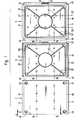
- a charging table 2 an exposure table 8 and a development table 9 of the charging, exposure or development station are shown.
- a printing form in the form of a printing plate is transported in the transport direction A from one processing station to the next processing station, as will be described in more detail later.
- pivotable flaps 5, 5 are attached, which are shown in FIG. 1 in a horizontally pivoted position, in which they lie in the plane of the charging table 2.
- two rows of air nozzles 18, 18 are arranged, which run obliquely within the tables and can be acted upon by compressed air.
- the compressed air creates an air cushion underneath the pressure plate, at a distance to the surfaces of the tables 2, 8, 9 the printing plate is suspended from one processing station to the next processing station.
- a jumping suction device 61 is arranged in the table near each corner of the charging table 2, the upper side of the piston of which, depending on the position of the piston, is either flush with the surface of the charging table 2 or lies slightly below the surface. With the suction cups 61, the pressure plate is sucked in, held and lifted off the charging table 2 as soon as it is to be transported from the charging station to the exposure station.
- the exposure table 8 is equipped with fixed guide plates 21, 22 on its narrow sides 46 and 47. In the middle of the longitudinal edge 49 of the exposure table 8 lying at the rear in the transport direction A there is an adjustable brake 6, which will be described in more detail below. In the surface of the exposure table 8 there is a network of interconnected vacuum channels 62 which are connected to a vacuum device, not shown, which generates a corresponding negative pressure for sucking and holding a printing plate on the exposure table 8.
- the development table 9 is equipped with pivotable flaps 24, 24 along its narrow sides 46, 47, which are arranged along the longitudinal sides 48, 49 of the development table 9.
- the surface of the development table 9 there are two further rows of air nozzles 23, 23 which run at right angles to the two rows of air nozzles 18, 18.
- the air nozzles 23, 23 enable the developed printing plate to be transported further at a right angle to the transport direction A.
- a system of vacuum channels 62 which is largely identical to the network of vacuum channels of the exposure table 8.
- the center of the rear longitudinal side 49 of the development table 9 is opposite another adjustable brake 6.
- the flap 24 located on this longitudinal side 49 has a recess 51 for the brake 6.
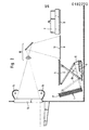
- the mode of operation of the device is explained on the basis of the schematic partial view shown in FIG. 2.
- a plate magazine 1 which is arranged inclined to the horizontal, there is a stack of pressure plates 17.
- the top edge of the stack or the top pressure plate 17 of the stack is always kept at the same level by means of a drive device, not shown.
- the inside of the plate magazine 1 facing photoconductive coating of the individual printing plate 17 is covered by a film or a sheet of paper, which when removing the Printing plate 17 is removed from the plate magazine 1.
- the support table 2 is brought into the position shown in broken lines by a swivel mechanism.
- This swivel mechanism consists of a cylinder 3, the piston rod of which is connected to one end of a coupling strut 10 which can be pivoted about a fixed point and is articulated at the other end to the underside of the charging table 2.
- Another coupling strut 11 is articulated at a fixed point 12 on the one hand and on the underside of the charging table on the other. If the piston rod of the cylinder 3 is retracted, the charging table 2, as already mentioned, is brought into the position shown in broken lines, in which the suction cups 61 grip the uppermost pressure plate in the plate magazine 1 and tighten it on the table surface. Then the piston rod of the cylinder 3 is extended so that the charging table 2 is pivoted into the horizontal charging position.
- the pressure plate 17 is still sucked onto the surface of the charging table 2 by means of the suction cups 61.
- the flaps 5, 5 are pivoted along the narrow sides 46, 47 of the charging table 2 into the plane of the charging table 2, so that a corona 4 can move a short distance from the pressure plate 17 without obstruction over the full length of the pressure plate 17 to charge the photoconductive layer of the pressure plate 17 to the required voltage.
- the flaps 5, 5 are placed upright, ie perpendicular to the surface of the charging table 2, and the vacuum of the suction cups 61 is released, so that when the air nozzles 18, 18 are pressurized with compressed or transport air, the resulting air cushion lifts the pressure plate 17 from the surface of the charging table 2 and transports it in the direction of the exposure table 8.
- the brake 6 (see FIG. 1), which is arranged on the one long side 49 of the exposure table 8, stops the movement of the printing plate 17.
- the printing plate 17 is guided and aligned by the stationary guide plates 21 and 22 of the exposure table 8, the The distance between these guide plates is approximately 1 mm greater than the length of the pressure plate 17.
- the transport or compressed air of the air nozzles 18, 18 of the exposure table 8 is switched off, the brake 6 is pivoted into a position lower than the surface of the exposure table 8, and the vacuum channels 62 of the exposure table 8 are subjected to negative pressure, so that the pressure plate 17 is sucked in.
- the printing plate 17 is then exposed by means of a template, not shown, which is inserted into a template holder 13 known per se.
- the light sources 14 and 15 form the original via an imaging optics 16 onto the printing plate 17 lying on the exposure table 8.
- the exposure time is controlled in accordance with the desired residual charging voltage, which is measured by means of a suitable probe, not shown, and as soon as the residual charging voltage is reached, the exposure is ended.
- the vacuum in the system of vacuum Channels 62 of the exposure table 8 is broken down, the transport or compressed air of the air nozzles 18, 18 of the exposure table 8 and the development table 9 is switched on, so that the printing plate 17 can be transported in the direction of the development table 9 while floating.
- the flaps 5.5 along the narrow sides 46 and 47 of the development table 9 are simultaneously pivoted upright.
- the further brake 6, which is arranged on the one long side 49 of the development table 9 at the point at which the pivotable flap 24 has the recess 51 (see FIG. 1), stops the pressure plate 17 in its end position.
- the transport or compressed air of the air nozzles 18, 18 is switched off and a vacuum is built up in the system of the vacuum channels 62, as a result of which the pressure plate is sucked onto the surface of the development table 9.
- a developing device 7, which contains dry toner, is moved over the exposed printing plate 17 and the latent image is developed by the dry toner.
- the vacuum in the vacuum channels 62 is released, the flaps 24, 24 are folded up on the long sides of the exposure table 9 and the transport or compressed air for the air nozzles 23, 23 is switched on.
- the two rows of air nozzles 23, 23 run at right angles to the rows of air nozzles 18, 18, so that the pressure plate 17 is transported out of the device in the direction of the starting position of the developing device 7.
- the flaps 24, 24 are folded down and the development device 7 is returned to its starting position. Another, already loaded and exposed printing plate is positioned on the development table 9 and the development process is started.
- FIG. 3 shows the transfer of a printing plate from the charging table 2 to the exposure table 8.
- the charging table 2 is shown broken away in the area of the two rows of air nozzles 18, 18, projections of the air nozzles 18, 18 in two mutually perpendicular planes for the sake of better clarity not being shown flat but only by lines.
- the projections 18 ', 18 "of the air nozzles 18, 18 of the two rows into the base plane of the table parallel to the table surface form an angle between 40 and 50 °, preferably 45 °, with the transport direction A of the pressure plate 17.
- These projections 18', 18 ′′ are directed at the associated narrow sides 46, 47 of the charging table 2 at this angle ⁇ .
- the same spatial arrangement also exists for the air nozzles 18, 18 of the exposure and development table 8 or 9.
- the distance d between the flaps 5.5 raised longitudinally and the associated narrow side 46 or 47 of the charging table 2 is 3 to 6 mm.
- the flaps 5.5 consist, for example, of structural sheets with a thickness of 1 mm.
- These air ducts between the flaps 5, 5 folded up and the narrow sides 46, 47 of the charging table 2 on the one hand and the guide plates 21, 22 and the narrow sides 46, 47 of the exposure table 8 on the other hand ensure that there is space below the edges of the pressure plate 17, can flow into the excess transport air and that moreover a stronger air cushion is formed than under the remaining surface of the pressure plate 17, so that sagging of the edges of the pressure plate 17 is prevented downwards.
- the distance between the two rows of air nozzles 18, 18 from one another is approximately 35 to 50% of the distance between the raised flaps 5.5 or between the fixed guide plates 21, 22, in particular the row distance is 40% of the distance between the flaps or the guide plates.
- the two rows of air nozzles 18, 18 are arranged symmetrically to the center line of each table in the transport direction A. For example, within a row of air nozzles 18 The distance between two adjacent air nozzles is 25 mm, the first and the last air nozzle 18 of a row being 50 mm away from the long sides. Although this is not shown, a strip of sheet metal or foil material can bridge the gap between two tables between the individual tables.
- FIGS. 4a and 4b An adjustment mechanism for the flaps 5, 5, which is identical to the adjustment mechanism for the flaps 24, 24, is shown schematically in detail in FIGS. 4a and 4b.
- the adjustment mechanism for the flaps 5, 5 of the charging table 2 is located in a plan view below the table 2.
- the two adjustment mechanisms for the flaps 5, 5 and 24, 24 of the development table 9 are attached below the same.
- the adjustment mechanism consists of a swivel plate 52, a pressure cylinder 53 acting on the swivel plate and two cables 54, 55 connecting the flaps to the swivel plate, which can be sheathed steel wires, for example.
- the ropes 54, 55 engage at one end at two diametrically opposite points near the circumference of the swivel plate 52, while their other ends are fastened in offset bores 56, 57 by metal blocks 58, 58.
- the bore 56 has a smaller diameter than the bore 57, in which the individual cable 54 or 55, which has a ball at its end, is introduced.
- the ball has a larger diameter than the bore 56, so that pulling out the cable in the direction of the swivel plate 52 from the offset bores is not possible.
- each metal block is mounted a flap 58.58 5 or 24, wherein the metal block about a pivot point 59 which is spaced from the respective cable 54 and 55, respectively, can be pivoted through an angle up to 90 0th
- the pressure cylinder 53 is fastened with its piston rod near the circumference of the swivel plate 52 at a point which lies on the bisector H of the fastening points for the cables 54, 55 on the swivel plate 52.
- 4a shows the extended position of the piston rod of the pressure cylinder 53, in which the flaps 5, 5 or 24, 24 are placed upright and form a right angle with the surface of the respective table.
- the swivel plate 52 executes a clockwise rotation, in which the cables 54 and 55 are pulled outwards, since the metal blocks 58, 58 pivot outwards about the pivot points 59, 59 and with them connected flaps 5,5 and 24,24 can be folded into the plane of the surface of the respective table.
- a stop 60 for example a screw, is attached, which limits the pivoting movement of the metal blocks 58, 58 when the flaps are pivoted upright.
- the pivot points 59, 59 are in themselves designed as stub axles, which are surrounded by leg springs, not shown are that ensure an elastic mounting of the individual flaps.
- FIG. 5 shows a partial perspective view of a flap 24 which is arranged parallel to the longitudinal side 49 of the development table 9.
- the flap 24 is shown in the folded-down state with solid lines, while the flap 24 which is placed upright is indicated by dashed lines.
- the distance d between the long side 49 and the flap 24 placed upright is 3 to 6 mm.
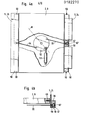
- the brake 6 shown schematically in FIG. 6 comprises two pressure cylinders 37 and 39 which are articulated on bearing blocks 36 and 40 of an angled fastening strut 35 of the brake.
- the fastening strut 35 is fastened to a spacer 44 which extends downwards from the underside of the exposure and development tables 8 and 9, respectively.
- the piston rod 34 of the one pressure cylinder 37 is connected to the other pressure cylinder 39 via an angled connecting piece 38, the connecting piece 38 being fastened directly to the housing of the printing cylinder 39.
- the damping element 42 brakes the one floating on the air cushion Pressure plate 17, springs back slightly and then pushes the pressure plate into the desired position, in which the transport air of the air nozzles is switched off and the vacuum in the vacuum channels in the surface of the table 8 or 9 is switched on, around the pressure plate 17 to the surface suck in.
- the two pressure cylinders 37 and 39 or their piston rods 34 and 41 are retracted.
- To initiate the braking process first the piston rod 34 of the pressure cylinder 37 is extended and then the piston rod 41 of the pressure cylinder 39 in order to bring the elastic damping element 42 into its braking position.
- the pivoting of the damping element 42 takes place in the reverse order, ie first the piston rod 41 of the pressure cylinder 39 retracts and then the piston rod 34 of the pressure cylinder 37.
- a recess 43 is formed below the table surface at the point at which the brake 6 is arranged a recessed cut-out is provided in the long side of the table in question, which enables the piston rod 41 of the pressure cylinder 39 to be extended without hindrance to a position in which the damping element 42 brakes the pressure plate 17 and can position it above the table.
- a cylindrical vacuum housing 27 of the suction cup 61 on the underside of the charging table 2 encloses a displaceable piston 29, the piston crown 28 of which rests against the bottom and the inner wall of the vacuum housing 27 and seals a vacuum chamber 32 which is located between the piston 29 and the cylindrical inner wall of the vacuum housing 27 extends.
- the vacuum chamber 32 is connected via a vacuum line 25 to a vacuum device, not shown.
- the piston 29 widens upwards to a frustoconical piston head 63, which projects into an open bore 30 of the charging table 2.
- a sleeve-like rubber seal 33 is inserted, the upper edge of which is in alignment with the table surface in the rest position of the suction cup 61.
- a compression spring 45 surrounds the piston 29 and is supported against the top of the piston head 28 on the one hand and against the inside of a top surface 65 of the vacuum housing 27 on the other hand.
- the stepped piston crown 28 there is a compensating bore 26 which connects the vacuum chamber 32 to a continuous bore 66 of the piston 29 which runs in the axial direction.
- the piston 29 moves upward in the vacuum housing 27, since the piston head 28 seals against the cylindrical inner wall and the bottom of the vacuum housing 27.
- This upward movement of the piston arises from the fact that there is atmospheric pressure in the bore 66, while there is a negative pressure in the vacuum chamber 32 and, because of the small diameter of the compensating bore 26, pressure compensation cannot initially occur between the bore 66 and the vacuum chamber 32.
- the atmospheric pressure in the bore 66 acts on the underside of the piston crown 28 with atmospheric pressure and thus pushes the piston 29 upward, since outside the piston 29 there is less pressure in the vacuum chamber 32 than in the bore 66.
- the pressure cylinders of the device are preferably operated with compressed air, but the use of hydraulic pressure cylinders is also possible.
Abstract
In der Vorrichtung sind ein Auflade-, ein Belichtungs- und ein Entwicklungstisch 2, 8, 9 in Transportrichtung A von Druckplatten hintereinander angeordnet. Der Aufladetisch 2 ist schwenkbar und mit Springsaugern 61 ausgerüstet, mit deren Hilfe die oberste Druckplatte einem Plattenmagazin entnommen wird. Nach der Druckplattenentnahme wird der Aufladetisch 2 in seine horizontale Arbeitsstellung geschwenkt, eine Korona über den Aufladetisch 2 bewegt und die fotoleitfähige Schicht der Druckplatte auf die erforderliche Spannung aufgeladen. Der Transport der Druckplatte von dem Aufladetisch 2 zu dem Belichtungstisch 8 und von diesem zu dem Entwicklungstisch 9 erfolgt mit Hilfe von Druckluft, welche ein Polster unterhalb der Druckplatte bildet, auf dem diese schwebend von Bearbeitungsstation zu Bearbeitungsstation geführt wird. Hierzu sind in den Tischen der Bearbeitungsstationen zumindest zwei Reihen von Luftdüsen 18, 18 angeordnet, die innerhalb der Tische schräg verlaufen und mit Druckluft beaufschlagt werden. Der Aufladetisch 2 ist an den Schmalseiten 46, 47 mit schwenkbaren Klappen 5, 5 ausgerüstet. Der Belichtungstisch 8 weist an den Schmalseiten ortsfeste Führungsbleche 21, 22 auf, während der Entwicklungstisch 9 an allen vier Seiten mit schwenkbaren Klappen 5, 5 bzw. 24, 24 ausgestattet ist und darüber hinaus noch zwei Reihen von Luftdüsen 23, 23 besitzt, die im rechten Winkel zu den Luftdüsen 18, 18 angeordnet sind.In the device, a charging, an exposure and a development table 2, 8, 9 in the transport direction A of printing plates are arranged one behind the other. The loading table 2 is pivotable and equipped with suction cups 61, with the help of which the uppermost pressure plate is removed from a plate magazine. After the printing plate has been removed, the charging table 2 is pivoted into its horizontal working position, a corona is moved over the charging table 2 and the photoconductive layer of the printing plate is charged to the required voltage. The transport of the printing plate from the charging table 2 to the exposure table 8 and from this to the development table 9 takes place with the aid of compressed air, which forms a cushion below the printing plate, on which it is guided from the processing station to the processing station in a floating manner. For this purpose, at least two rows of air nozzles 18, 18 are arranged in the tables of the processing stations, which run obliquely within the tables and are supplied with compressed air. The loading table 2 is equipped on the narrow sides 46, 47 with pivotable flaps 5, 5. The exposure table 8 has stationary guide plates 21, 22 on the narrow sides, while the development table 9 is equipped on all four sides with pivotable flaps 5, 5 and 24, 24 and also has two rows of air nozzles 23, 23, which in the right angles to the air nozzles 18, 18 are arranged.
Description
Die Erfindung betrifft eine Vorrichtung zur elektrofotografischen Herstellung von Druckformen, die im unDelichteten Zustand in einem Magazin gestapelt sind und mittels Saugelementen dem Magazin einzeln entnommen und zu einer Aufladestation transportiert werden, um von dort zu weiteren Bearbeitungsstationen der Vorrichtung bewegt zu werden.The invention relates to a device for the electrophotographic production of printing forms which are stacked in the undelected state in a magazine and are individually removed from the magazine by means of suction elements and transported to a charging station in order to be moved from there to further processing stations of the device.
Aus der DE-OS 30 12 815 ist eine derartige Vorrichtung bekannt, die einen um eine Achse schwenkbaren Hubzylinder mit einer aus dem Hubzylinder aus- und in diesen einfahrbaren Kolbenstange aufweist, die an der unbeschichteten Seite der Druckform angreifende Saugelemente für das Ansaugen und Absetzen der obersten Druckplatte des Stapels trägt. Die Saugelemente zum Ansaugen, Festhalten und Absetzen der Druckform auf eine horizontale Förderbahn sind auf einer schüsselförmigen Platte angeordnet, die als Halterung der Saugelemente mit der Kolbenstange verbunden ist. Die Förderbahn ist ein Tisch, längs dem die Druckform zu einem dahinter angeordneten Belichtungstisch transportiert wird. Das Magazin ist zur Senkrechten geneigt, wobei der Hubzylinder in seiner Aufnahmeposition senkrecht auf die unbeschichtete Seite der obersten Druckform gerichtet ist und die schüsselförmige Platte parallel zu der unbeschichteten Seite der Druckform verläuft und auf diese zum Abheben der obersten Platte von dem Stapel soweit abgesenkt wird, bis die Saugelemente auf der Druckform aufsitzen.From DE-OS 30 12 815 such a device is known, which has a pivotable about an axis lifting cylinder with a from the lifting cylinder and retractable in this piston rod, which acts on the uncoated side of the printing form suction elements for sucking and depositing the top pressure plate of the stack. The suction elements for sucking, holding and depositing the printing form on a horizontal conveyor track are arranged on a bowl-shaped plate which is connected to the piston rod as a holder for the suction elements. The conveyor track is a table along which the printing form is transported to an exposure table arranged behind it. The magazine is inclined to the vertical, the lifting cylinder in its receiving position being directed perpendicularly onto the uncoated side of the uppermost printing form and the bowl-shaped plate running parallel to the uncoated side of the printing form and onto this for lifting off the top plate is lowered from the stack until the suction elements sit on the printing form.
In der DE-PS 24 62 216 ist ein Gerät zur elektrofotografischen Herstellung von Druckformen beschrieben, bei dem die einzelne Druckform von einem Stapel in einem Plattenmagazin durch eine Transportvorrichtung abgehoben wird, die aus einem Transportwagen mit einer Unterdrucksaugeinrichtung besteht und welche die Druckform zu einer Belichtungsbühne transportiert. Der Transportwagen läuft über zwei Führungsschienen und ist von einem auf der Oberseite angeordneten Motor antreibbar, der über ein Zahnrad mit einem Zahnstangenantrieb im Eingriff steht, der parallel zu der Bewegungsrichtung des Transportwagens angeordnet ist. Der Transportwagen weist an der Unterseite eine Vakuumplatte auf, die über eine Anzahl von Löchern mit einer Vakuumpumpe in Verbindung steht. Beim Aufsetzen des Transportwagens auf die Oberseite der obersten Druckplatte im Plattenmagazin wird die Druckplatte durch Unterdruck an die Vakuumplatte angesaugt und danach wird der Transportwagen in Richtung der Belichtungsbühne verfahren. Es erfolgt eine Absenkung auf die Belichtungsbühne und das Absetzen der Druckplatte auf die Belichtungsbühne, indem das Vakuum in der Vakuumplatte des Transportwagens aufgehoben wird. Die Belichtungsbühne umfaßt eine Vakuumplatte, die mit Unterdruck beaufschlagt wird, um die Druckplatte anzusaugen.DE-PS 24 62 216 describes a device for the electrophotographic production of printing forms in which the individual printing form is lifted from a stack in a plate magazine by a transport device which consists of a transport carriage with a vacuum suction device and which forms the printing form to an exposure stage transported. The transport carriage runs over two guide rails and can be driven by a motor which is arranged on the upper side and which engages via a gearwheel with a rack and pinion drive which is arranged parallel to the direction of movement of the transport carriage. The transport trolley has a vacuum plate on the underside, which is connected to a vacuum pump via a number of holes. When the transport carriage is placed on the top of the top printing plate in the plate magazine, the printing plate is sucked onto the vacuum plate by negative pressure and then the transport carriage is moved in the direction of the exposure stage. The exposure platform is lowered and the printing plate is lowered onto the exposure platform by releasing the vacuum in the vacuum plate of the transport carriage. The exposure stage comprises a vacuum plate, which is subjected to negative pressure in order to suck up the pressure plate.
Aus der DE-OS 30 12 761 ist eine Vorrichtung bekannt, mit der eine kreisbogenförmig von oben auf eine Auflagefläche abgesenkte Druckplatte, deren fotoleitfähig beschichtete Seite nach oben gerichtet ist, an eine mit Rollen ausgerüstete Vorrichtung für den Weitertransport übergeben wird, ohne daß die Druckplatte beim Absenken auf den Rollen zu liegen kommt und ohne daß die fotoleitfähige Schicht der Druckplatte mit den Rollen in Berührung gelangt. Dazu entnimmt ein schwenkbarer Hubzylinder die Druckform in Gestalt einer Druckplatte einem Magazin und legt die Druckplatte kreisbogenförmig mit dem Vorderteil auf eine Saugplatte des Belichtungstisches auf. Parallel zu den beiden Seitenkanten der Druckplatte in Transportrichtung ist je eine Reihe von Transport- und Antriebsrollen angeordnet, wobei die in Transportrichtung der Druckplatte zuerst liegenden Transportrollen aus den Reihen nach außen schwenkbar sind, um ein klemmfreies Ablegen des Vorderteils der Druckplatte auf die Saugplatte des Belichtungstisches zu ermöglichen. Nach der Ablage der Druckplatte auf dem Belichtungstisch liegen die beiden zueinander parallelen Rollenleisten mit den Transport- und Antriebsrollen an den Seitenkanten der Druckplatte an und zentrieren diese während der Belichtung. Da die Rollen eine bestimmte Rillentiefe besitzen, stehen sie am Rand bzw. an den Seitenkanten der Druckplatte in deren Inneres um diese Rillentiefe über, so daß eine Belichtung der Druckplatte bis zum Rand hin nicht möglich ist.From DE-OS 30 12 761 a device is known with which a printing plate lowered in a circular arc from above onto a support surface, the photoconductively coated side of which is directed upwards, is transferred to a device equipped with rollers for further transport, without the printing plate coming to rest on the rollers during lowering and without the photoconductive device Layer of the pressure plate comes into contact with the rollers. For this purpose, a swiveling lifting cylinder takes the printing form in the form of a printing plate from a magazine and places the printing plate in a circular arc with the front part on a suction plate of the exposure table. A row of transport and drive rollers is arranged parallel to the two side edges of the printing plate in the transport direction, the transport rollers lying first in the transport direction of the printing plate being pivotable outwards from the rows in order to place the front part of the printing plate on the suction plate of the exposure table without jamming to enable. After the printing plate has been placed on the exposure table, the two parallel roller strips with the transport and drive rollers lie against the side edges of the printing plate and center them during the exposure. Since the rollers have a certain groove depth, they protrude on the edge or on the side edges of the pressure plate inside by this groove depth, so that exposure of the pressure plate to the edge is not possible.
In der DE-OS 31 22 321 wird eine Einzugs- und Transportvorrichtung für Druckplatten beschrieben, die eine Belichtung der Druckplatte über die gesamte Breite hin bis zu den Außenkanten ermöglicht, indem die Rollen drehbar auf Böcken gelagert sind, die auf zwei zueinander parallelen und beweglichen Rollenleisten befestigt sind, und Einrichtungen vorgesehen sind, um vor der Belichtung die Rollenleisten parallel zu den Seitenkanten der Druckplatte nach außen zu verschieben.In DE-OS 31 22 321 a Einzugs- and Trans Port device for printing plates described, which allows exposure of the printing plate over the entire width to the outer edges by the rollers are rotatably mounted on trestles, which are fastened on two mutually parallel and movable roller strips, and means are provided to prior to exposure to move the roller strips outwards parallel to the side edges of the pressure plate.
Die bekannten Einzugs- und Transportvorrichtungen arbeiten mechanisch und umfassen entweder einen, die einzelne Druckplatte von Bearbeitungsstation zu Bearbeitungsstation verfahrenden Transportwagen, der die Druckplatte durch Vakuum festhält, oder angetriebene Transportrollen, die mit den Seitenkanten der Druckplatte in Berührung stehen, um diese weiterzutransportieren. Diese Vorrichtungen arbeiten zufriedenstellend, sind jedoch mechanisch aufwendig aufgebaut und ihre Transportkapazität ist auf etwa 60 Platten pro Minute begrenzt. Ein höherer Plattendurchsatz ist kaum zu erreichen, da infolge der Trägheit der mechanischen Teile der Transportvorrichtung deren Inbetriebsetzen und Anhalten für das Aufnehmen von einem Tisch einer Bearbeitungsstation und die Übergabe einer einzelnen Druckplatte von Bearbeitungsstation zu Bearbeitungsstation eine höhere Arbeitsfrequenz nicht zulassen.The known feed and transport devices work mechanically and comprise either a transport carriage which moves the individual printing plate from processing station to processing station and holds the printing plate by vacuum, or driven transport rollers which are in contact with the side edges of the printing plate in order to transport them further. These devices work satisfactorily, but are mechanically complex and their transport capacity is limited to about 60 plates per minute. A higher plate throughput can hardly be achieved because, due to the inertia of the mechanical parts of the transport device, their starting and stopping for picking up from a table of a processing station and the transfer of a single printing plate from processing station to processing station do not allow a higher working frequency.
Aufgabe der Erfindung ist es, eine Vorrichtung der eingangs beschriebenen Art so zu verbessern, daß sie eine höhere Transportgeschwindigkeit für Druckformen ohne Beeinträchtigung der Transportsicherheit ermöglicht.The object of the invention is to improve a device of the type described above so that it enables a higher transport speed for printing forms without impairing transport safety.
Diese Aufgabe wird erfindungsgemäß dadurch gelöst, daß die einzelne Druckform in Gestalt einer Druckplatte mit Hilfe von Druckluft im Abstand zu den Oberflächen von Tischen der Bearbeitungsstationen von einer Bearbeitungsstation zur nächsten Bearbeitungsstation schwebend geführt ist und daß in den Tischen zumindest zwei Reihen von Luftdüsen angeordnet sind, die innerhalb der Tische schräg verlaufen und mit Druckluft beaufschlagt sind.This object is achieved in that the individual printing form in the form of a printing plate is guided with the aid of compressed air at a distance from the surfaces of tables of the processing stations from one processing station to the next processing station and that at least two rows of air nozzles are arranged in the tables, that run obliquely inside the tables and are pressurized with compressed air.
In Ausgestaltung der Erfindung sind die beiden Reihen von Luftdüsen in der Oberfläche jedes Tisches parallel zu der Transportrichtung der Druckplatte bzw. parallel zu den Schmalseiten der Tische ausgerichtet und sind des weiteren im Tisch der Entwicklungsstation zwei weitere Reihen von Luftdüsen vorhanden, die rechtwinklig zu den beiden Reihen von Luftdüsen verlaufen. Die schräg verlaufenden Luftdüsen sind räumlich derart angeordnet, daß die Projektionen der Luftdüsen der beiden Reihen in die zur Tischoberfläche parallele Grundebene Winkel zwischen 40° und 50° mit der Transportrichtung der Druckplatte einschließen und daß diese Projektionen unter diesem Winkel auf die zugehörigen Schmalseiten des einzelnen Tisches gerichtet sind. Ferner schließen die Projektionen der Luftdüsen der beiden Reihen in eine zu den Längsseiten des einzelnen Tisches parallele Ebene einen Winkel zwischen 400 und 500 mit der senkrechten Richtung auf die Transportrichtung der Druckplatte ein.In an embodiment of the invention, the two rows of air nozzles in the surface of each table are aligned parallel to the transport direction of the pressure plate or parallel to the narrow sides of the tables, and there are also two further rows of air nozzles in the table of the development station, which are perpendicular to the two Rows of air jets run. The oblique air nozzles are spatially arranged in such a way that the projections of the air nozzles of the two rows in the basic plane parallel to the table surface include angles between 40 ° and 50 ° with the transport direction of the printing plate, and that these projections at this angle onto the associated narrow sides of the individual table are directed. Furthermore, the projections of the air nozzles of the two rows close in on the long sides of the individual NEN table parallel plane an angle between 40 0 and 50 0 with the vertical direction of the transport direction of the printing plate.
Zur Stabilisierung des Luftpolsters, auf dem die einzelne Druckplatte von Bearbeitungsstation zu Bearbeitungsstation geführt wird, sind der Tisch der Aufladestation und der Tisch der Entwicklungsstation mit schwenkbaren Klappen ausgerüstet, die entlang den Schmalseiten des einzelnen Tisches so angeordnet sind, daß der Abstand d zwischen den längskant hochgestellten Klappen und der zugehörigen Schmalseite drei bis sechs Millimeter beträgt. Der Tisch der Belichtungsstation besitzt keine schwenkbaren Klappen, sondern statt dessen lagefeste Führungsbleche entlang den Schmalseiten des Tisches. Diese Führungsbleche schließen mit den Schmalseiten der Belichtungsstation Luftkanäle ein, die eine Breite von 3 - 6 mm und eine Tiefe von 5 - 10 mm aufweisen.To stabilize the air cushion on which the individual printing plate is guided from processing station to processing station, the table of the charging station and the table of the development station are equipped with pivotable flaps which are arranged along the narrow sides of the individual table in such a way that the distance d between the longitudinal edges raised flaps and the associated narrow side is three to six millimeters. The table of the exposure station does not have swiveling flaps, but instead has fixed guide plates along the narrow sides of the table. With the narrow sides of the exposure station, these guide plates enclose air ducts which are 3 to 6 mm wide and 5 to 10 mm deep.
In Weiterbildung der Erfindung beträgt der Abstand der beiden Reihen von Luftdüsen voneinander 35 - 50 % des Abstandes zwischen den hochgestellten Klappen bzw. den lagefesten Führungsblechen. Der Tisch der Entwicklungsstation ist zusätzlich zu den Klappen an den Schmalseiten mit schwenkbaren Klappen an den Längsseiten ausgerüstet.In a further development of the invention, the distance between the two rows of air nozzles is 35-50% of the distance between the raised flaps or the fixed guide plates. In addition to the flaps on the narrow sides, the table of the development station is equipped with swiveling flaps on the long sides.
Zur exakten Positionierung der Druckplatte für die weitere Bearbeitung auf dem Tisch der jeweiligen Bearbeitungsstation ist an einer der Längsseiten der Tische der Belichtungs- und der Entwicklungsstation je eine verstellbare Bremse angeordnet, die zwei Druckzylinder umfaßt, die an Lagerböcken einer gewinkelten Befestigungsstrebe der Bremse angelenkt sind. Die Befestigungsstrebe ist an einem Distanzstück befestigt, das mit der Unterseite des jeweiligen Tisches verbunden ist.For exact positioning of the printing plate for further processing on the table of the respective processing station, the is on one of the long sides Tables of the exposure and development stations each have an adjustable brake which comprises two pressure cylinders which are articulated on bearing blocks of an angled fastening strut for the brake. The fastening strut is attached to a spacer which is connected to the underside of the respective table.
Die weitere Ausgestaltung der Erfindung ergibt sich aus den Merkmalen der Patentansprüche 12 bis 17.The further embodiment of the invention results from the features of
Die Erfindung wird im folgenden anhand der Zeichnungen näher erläutert.The invention is explained in more detail below with reference to the drawings.
Es zeigen:
- Fig. 1 eine schematische Draufsicht auf die Tische dreier Bearbeitungsstationen einer Belichtungs- und Entwicklungsvorrichtung zum Herstellen von Druckplatten nach der Erfindung;
- Fig. 2 eine schematische Teilansicht der Vorrichtung nach der Erfindung;
- Fig. 3 eine perspektivische Ansicht der Tische der Auflade- und der Belichtungsstation der Vorrichtung;
- Fig. 4a Einzelheiten eines Verstellmechanismus und 4b für Klappen an den Tischen der Auflade- und der Entwicklungsstation;
- Fig. 5 eine perspektivische Ansicht einer Klappe an der Längsseite des Tisches der Belichtungsstation;
- Fig. 6 eine Seitenansicht einer Bremse zum Anhalten und Positionieren einer Druckplatte auf einem Tisch; und
- Fig. 7 eine Schnittansicht eines Springsaugers zum Ansaugen und Abheben einer Druckplatte auf bzw. von der Oberfläche des Tisches der Aufladestation.
- Figure 1 is a schematic plan view of the tables of three processing stations of an exposure and developing device for producing printing plates according to the invention.
- Fig. 2 is a schematic partial view of the device according to the invention;
- Figure 3 is a perspective view of the tables of the charging and exposure stations of the device;
- Fig. 4a details of an adjustment mechanism and 4b for flaps on the tables of the charging and the development station;
- 5 shows a perspective view of a flap on the long side of the table of the exposure station;
- 6 is a side view of a brake for stopping and positioning a pressure plate on a table; and
- Fig. 7 is a sectional view of a jumping vacuum for sucking and lifting a pressure plate on or from the surface of the table of the charging station.
In der schematischen Draufsicht nach Fig. 1 sind ein Aufladetisch 2, ein Belichtungstisch 8 und ein Entwicklungstisch 9 der Auflade-, Belichtungs- bzw. Entwicklungsstation dargestellt. Eine Druckform in Gestalt einer Druckplatte wird in Transportrichtung A von einer Bearbeitungsstation zu der nächsten Bearbeitungsstation transportiert, wie später noch näher beschrieben werden wird. An den Schmalseiten 46,47 des Aufladetisches 2 sind schwenkbare Klappen 5,5 angebracht, die in Fig. 1 in horizontal ausgeschwenkter Lage gezeichnet sind, in der sie in der Ebene des Aufladetisches 2 liegen. In jedem der Tische 2,8,9 sind zwei Reihen von Luftdüsen 18,18 angeordnet, die innerhalb der Tische schräg verlaufen und mit Druckluft beaufschlagbar sind. Durch die Druckluft entsteht unterhalb der Druckplatte ein Luftpolster, auf dem im Abstand zu den Oberflächen der Tische 2,8,9 die Druckplatte von einer Bearbeitungsstation zur nächsten Bearbeitungsstation schwebend geführt wird. Nahe jeder Ecke des Aufladetisches 2 ist ein Springsauger 61 im Tisch angeordnet, dessen Kolbenoberseite, je nach Stellung des Kolbens, entweder mit der Oberfläche des Aufladetisches 2 fluchtet bzw. geringfügig unterhalb der Oberfläche liegt. Mit den Springsaugern 61 wird die Druckplatte angesaugt, festgehalten und von dem Aufladetisch 2 abgehoben, sobald sie von der Aufladestation zu der Belichtungsstation transportiert werden soll.In the schematic plan view according to FIG. 1, a charging table 2, an exposure table 8 and a development table 9 of the charging, exposure or development station are shown. A printing form in the form of a printing plate is transported in the transport direction A from one processing station to the next processing station, as will be described in more detail later. On the
Die beiden Reihen von Luftdüsen 18,18 in den Oberflächen der Tische 2,8 und 9, wobei unter den Reihen die Öffnungen der Luftdüsen in den Tischoberflächen zu verstehen sind, verlaufen parallel zur Transportrichtung A der Druckplatte bzw. parallel zu den Schmalseiten der Tische.The two rows of
Der Belichtungstisch 8 ist mit lagefesten Führungsblechen 21,22 an seinen Schmalseiten 46 und 47 ausgerüstet. In der Mitte der in Transportrichtung A hinten liegenden Längskante 49 des Belichtungstisches 8 befindet sich eine verstellbare Bremse 6, die nachstehend noch näher beschrieben werden wird. In der Oberfläche des Belichtungstisches 8 ist ein Netz von untereinander in Verbindung stehenden Vakuumkanälen 62 vorhanden, die an eine nicht dargestellte Vakuumeinrichtung angeschlossen sind, die einen entsprechenden Unterdruck zum Ansaugen und Festhalten einer Druckplatte auf dem Belichtungstisch 8 erzeugt.The exposure table 8 is equipped with
Der Entwicklungstisch 9 ist zusätzlich zu den schwenkbaren Klappen 5,5 entlang seiner Schmalseiten 46,47 mit schwenkbaren Klappen 24,24 ausgerüstet, die entlang der Längsseiten 48,49 des Entwicklungstisches 9 angeordnet sind. In der Oberfläche des Entwicklungstisches 9 sind zwei weitere Reihen von Luftdüsen 23,23 vorhanden, die rechtwinklig zu den beiden Reihen von Luftdüsen 18,18 verlaufen. Die Luftdüsen 23,23 ermöglichen einen Weitertransport der entwickelten Druckplatte unter einem rechten Winkel zu der Transportrichtung A. In der Oberfläche des Entwicklungstisches 9 befindet sich ein System von Vakuumkanälen 62, das weitgehend identisch zu dem Netz von Vakuumkanälen des Belichtungstisches 8 ist. Der Mitte der hinteren Längsseite 49 des Entwicklungstisches 9 liegt eine weitere verstellbare Bremse 6 gegenüber. Die an dieser Längsseite 49 befindliche Klappe 24 weist eine Ausnehmung 51 für die Bremse 6 auf.In addition to the
Anhand der in Fig. 2 dargestellten schematischen Teilansicht der Vorrichtung wird deren Arbeitsweise erläutert. In einem Plattenmagazin 1, das geneigt zu der Horizontalen angeordnet ist, befindet sich ein Stapel von Druckplatten 17. Die Oberkante des Stapels bzw. die oberste Druckplatte 17 des Stapels wird mittels einer nicht dargestellten Antriebseinrichtung immer auf dem gleichen Niveau gehalten. Die ins Innere des Plattenmagazins 1 weisende fotoleitfähige Beschichtung der einzelnen Druckplatte 17 ist durch eine Folie oder ein Papierblatt abgedeckt, das bei der Entnahme der Druckplatte 17 aus dem Plattenmagazin 1 entfernt wird. Um eine Druckplatte 17 in den Arbeitsablauf einzubringen, wird der Auflagetisch 2 durch einen Schwenkmechanismus in die gestrichelt gezeichnete Position gebracht. Dieser Schwenkmechanismus besteht aus einem Zylinder 3, dessen Kolbenstange mit einem Ende einer Kopplungsstrebe 10 verbunden ist, die um einen festen Punkt verschwenkbar und mit ihrem anderen Ende an der Unterseite des Aufladetisches 2 angelenkt ist. Eine weitere Kopplungsstrebe 11 ist an einem ortsfesten Punkt 12 einerseits und an der Unterseite des Aufladetisches andererseits angelenkt. Wird die Kolbenstange des Zylinders 3 eingefahren, so wird der Aufladetisch 2, wie schon erwähnt, in die gestrichelt gezeichnete Position gebracht, in der die Springsauger 61 die oberste Druckplatte im Plattenmagazin 1 ergreifen und an die Tischoberfläche anziehen. Anschließend wird die Kolbenstange des Zylinders 3 ausgefahren, so daß der Aufladetisch 2 in die horizontale Aufladeposition geschwenkt wird. Die Druckplatte 17 ist dabei weiterhin an die Oberfläche des Aufladetisches 2 mittels der Springsauger 61 angesaugt. In der Aufladeposition sind die Klappen 5,5 entlang den Schmalseiten 46,47 des Aufladetisches 2 in die Ebene des Aufladetisches 2 geschwenkt, so daß sich eine Korona 4 im geringen Abstand zur Druckplatte 17, ohne Behinderung über die volle Länge der Druckplatte 17 bewegen kann, um die fotoleitfähige Schicht der Druckplatte 17 auf die erforderliche Spannung aufzuladen. Nach dem Aufladevorgang werden die Klappen 5,5 hochkant gestellt, d.h. senkrecht zu der Oberfläche des Aufladetisches 2, und das Vakuum der Springsauger 61 aufgehoben, so daß bei Beaufschlagung der Luftdüsen 18,18 mit Druck- bzw. Transportluft das entstehende Luftpolster die Druckplatte 17 von der Oberfläche des Aufladetisches 2 abhebt und in Richtung des Belichtungstisches 8 schwebend transportiert. Die Bremse 6 (vgl. Fig. 1), die an der einen Längsseite 49 des Belichtungstisches 8 angeordnet ist, stoppt die Bewegung der Druckplatte 17. Die Druckplatte 17 wird durch die ortsfesten Führungsbleche 21 und 22 des Belichtungstisches 8 geführt und ausgerichtet, wobei der Abstand dieser Führungsbleche voneinander um ca. 1 mm größer als die Länge der Druckplatte 17 ist. Nach dem Anhalten der ausgerichteten Druckplatte 17 wird die Transport- bzw. Druckluft der Luftdüsen 18,18 des Belichtungstisches 8 abgeschaltet, die Bremse 6 in eine Lage tiefer als die Oberfläche des Belichtungstisches 8 abgeschwenkt und die Vakuumkanäle 62 des Belichtungstisches 8 mit Unterdruck beaufschlagt, so daß die Druckplatte 17 angesaugt wird. Es erfolgt dann die Belichtung der Druckplatte 17 durch eine nicht dargestellte Vorlage, die in eine an sich bekannte Vorlagenhalterung 13 eingelegt ist. Die Lichtquellen 14 und 15 bilden die Vorlage über eine Abbildungsoptik 16 auf die auf dem Belichtungstisch 8 aufliegende Druckplatte 17 ab. Die Belichtungszeit wird entsprechend der gewünschten Restaufladespannung, die mittels einer geeigneten, nicht dargestellten Sonde gemessen wird, gesteuert und sobald die Restaufladespannung erreicht ist, wird die Belichtung beendet. Das Vakuum im System der Vakuumkanäle 62 des Belichtungstisches 8 wird abgebaut, die Transport- bzw. Druckluft der Luftdüsen 18,18 des Belichtungstisches 8 und des Entwicklungstisches 9 eingeschaltet, so daß die Druckplatte 17 in Richtung des Entwicklungstisches 9 schwebend weitertransportiert werden kann. Die Klappen 5,5 entlang den Schmalseiten 46 und 47 des Entwicklungstisches 9 werden gleichzeitig hochkant geschwenkt.The mode of operation of the device is explained on the basis of the schematic partial view shown in FIG. 2. In a plate magazine 1, which is arranged inclined to the horizontal, there is a stack of
Die weitere Bremse 6, die an der einen Längsseite 49 des Entwicklungstisches 9 an der Stelle angeordnet ist, an der die schwenkbare Klappe 24 die Ausnehmung 51 (vgl. Fig. 1) aufweist, stoppt die Druckplatte 17 in ihrer Endstellung. Die Transport- bzw. Druckluft der Luftdüsen 18,18 wird abgeschaltet und in dem System der Vakuumkanäle 62 ein Vakuum aufgebaut, wodurch die Druckplatte an die Oberfläche des Entwicklungstisches 9 angesaugt wird. Eine Entwicklungseinrichtung 7, die Trockentoner enthält, wird über die belichtete Druckplatte 17 verfahren und das Latentbild durch den Trockentoner entwickelt. In der Endstellung der Entwicklungseinrichtung 7 wird das Vakuum in den Vakuumkanälen 62 abgebaut, die Klappen 24,24 an den Längsseiten des Belichtungstisches 9 hochgeklappt und die Transport- bzw. Druckluft für die Luftdüsen 23,23 eingeschaltet. Die beiden Reihen von Luftdüsen 23,23 verlaufen im rechten Winkel zu den Reihen der Luftdüsen 18,18, so daß die Druckplatte 17 in Richtung der Anfangsposition der Entwicklungseinrichtung 7 aus der Vorrichtung transportiert wird. Nachdem die Druckplatte 17 den Entwicklungstisch 9 verlassen hat, werden die Klappen 24,24 abgeklappt und die Entwicklungseinrichtung 7 in ihre Ausgangsstellung zurückgefahren. Eine weitere, schon aufgeladene und belichtete Druckplatte wird auf dem Entwicklungstisch 9 positioniert und der Entwicklungsvorgang begonnen.The
Aus Fig. 3 ist die Übergabe einer Druckplatte von dem Aufladetisch 2 auf den Belichtungstisch 8 ersichtlich. Der Aufladetisch 2 ist im Bereich der zwei Reihen von Luftdüsen 18,18 aufgebrochen dargestellt, wobei Projektionen der Luftdüsen 18,18 in zwei zueinander senkrechte Ebenen aus Gründen der besseren Übersichtlichkeit nicht flächig, sondern nur durch Linien dargestellt sind. Die Projektionen 18',18" der Luftdüsen 18,18 der beiden Reihen in die zur Tischoberfläche parallele Grundebene des Tisches schließen einen Winkel zwischen 40 und 50°, bevorzugt 45°, mit der Transportrichtung A der Druckplatte 17 ein. Diese Projektionen 18',18" sind unter diesem Winkel a auf die zugehörigen Schmalseiten 46,47 des Aufladetisches 2 gerichtet. Die gleiche räumliche Anordnung liegt auch bei den Luftdüsen 18,18 des Belichtungs- und Entwicklungstisches 8 bzw. 9 vor.3 shows the transfer of a printing plate from the charging table 2 to the exposure table 8. The charging table 2 is shown broken away in the area of the two rows of
Die Projektionen 18'",18'" der Luftdüsen 18,18 der beiden Reihen in eine zu den Längsseiten des einzelnen Tisches 2,8,9 parallele Ebene schließen einen Winkel ß zwischen 40 und 50°, bevorzugt 45°, mit der senkrechten Richtung auf die Transportrichtung A der Druckplatte 17 ein.The projections 18 '", 18'" of the
Der Abstand d zwischen den längskant hochgestellten Klappen 5,5 und der zugehörigen Schmalseite 46 bzw. 47 des Aufladetisches 2 beträgt 3 bis 6 mm. Die Klappen 5,5 bestehen beispielsweise aus Strukturblechen mit einer Dicke von 1 mm.The distance d between the flaps 5.5 raised longitudinally and the associated
Die Führungsbleche 21,22, die entlang den Schmalseiten 46,47 des Belichtungstisches 8 angeordnet sind, schließen mit diesen Schmalseiten Luftkanäle 19,20 mit einer Breite b von 3 bis 6 mm und einer Tiefe a von 5 bis 10 mm ein. Durch diese Luftkanäle zwischen den hochgeklappten Klappen 5,5 und den Schmalseiten 46,47 des Aufladetisches 2 einerseits und den Führungsblechen 21,22 und den Schmalseiten 46,47 des Belichtungstisches 8 andererseits wird sichergestellt, daß unterhalb der Kanten der Druckplatte 17 Raum vorhanden ist, in den überschüssige Transportluft einströmen kann und daß sich darüber hinaus ein kräftigeres Luftpolster als unter der übrigen Fläche der Druckplatte 17 ausbildet, so daß ein Durchsacken der Kanten der Druckplatte 17 nach unten verhindert wird. Der Abstand zwischen den beiden Reihen von Luftdüsen 18,18 voneinander beträgt etwa 35 bis 50 % des Abstandes zwischen den hochgestellten Klappen 5,5 bzw. zwischen den lagefesten Führungsblechen 21,22, insbesondere beträgt der Reihenabstand 40 % des Abstandes zwischen den Klappen bzw. den Führungsblechen. Die beiden Reihen von Luftdüsen 18,18 sind symmetrisch zu der Mittellinie jedes Tisches in Transportrichtung A angeordnet. Innerhalb einer Reihe von Luftdüsen 18 kann beispielsweise der Abstand zwischen zwei benachbarten Luftdüsen 25 mm betragen, wobei die erste und die letzte Luftdüse 18 einer Reihe von den Längsseiten 50 mm entfernt sind. Obwohl dies nicht dargestellt ist, kann zwischen den einzelnen Tischen jeweils ein Streifen aus Blech oder aus Folienmaterial den Spalt zwischen zwei Tischen überbrücken.The
Ein Verstellmechanismus für die Klappen 5,5, der identisch ist mit dem Verstellmechanismus für die Klappen 24,24 ist in Einzelheiten in den Fig. 4a und 4b schematisch dargestellt. Der Verstellmechanismus für die Klappen 5,5 des Aufladetisches 2 befindet sich in Draufsicht unterhalb des Tisches 2. Ebenso sind die beiden Verstellmechanismen für die Klappen 5,5 bzw. 24,24 des Entwicklungstisches 9 unterhalb desselben angebracht. Der Verstellmechanismus besteht aus einem Schwenkteller 52, einem an dem Schwenkteller angreifenden Druckzylinder 53 und zwei die Klappen mit dem Schwenkteller verbindenden Seilen 54,55, bei denen es sich beispielsweise um ummantelte Stahldrähte handeln kann. Die Seile 54,55 greifen an zwei sich diametral gegenüberliegenden Punkten nahe dem Umfang des Schwenktellers 52 mit den einen Enden an, während ihre anderen Enden in abgesetzten Bohrungen 56,57 von Metallblöcken 58,58 befestigt sind. Die Bohrung 56 besitzt einen kleineren Durchmesser als die Bohrung 57, in der das einzelne Seil 54 bzw. 55, das an seinem Ende eine Kugel aufweist, eingebracht ist. Die Kugel hat einen größeren Durchmesser als die Bohrung 56, so daß ein Herausziehen des Seils in Richtung des Schwenktellers 52 aus den abgesetzten Bohrungen nicht möglich ist. An jedem Metallblock 58,58 ist eine Klappe 5 bzw. 24 angebracht, wobei der Metallblock um einen Drehpunkt 59, der von dem jeweiligen Seil 54 bzw. 55 beabstandet ist, um einen Winkel bis zu 900 verschwenkt werden kann. Der Druckzylinder 53 ist mit seiner Kolbenstange nahe dem Umfang des Schwenktellers 52 an einem Punkt befestigt, der auf der Streckenhalbierenden H der Befestigungspunkte für die Seile 54,55 auf dem Schwenkteller 52 liegt. In Fig. 4a ist die ausgefahrene Stellung der Kolbenstange des Druckzylinders 53 dargestellt, in der die Klappen 5,5 bzw. 24,24 hochkant gestellt sind und mit der Oberfläche des jeweiligen Tisches einen rechten Winkel bilden. Wird die Kolbenstange des Druckzylinders 53 eingefahren, so führt der Schwenkteller 52 eine Drehung im Uhrzeigersinn aus, bei der die Seile 54 und 55 nach außen gezogen werden, da die Metallblöcke 58,58 um die Drehpunkte 59,59 nach außen schwenken und die mit ihnen verbundenen Klappen 5,5 bzw. 24,24 in die Ebene der Oberfläche des jeweiligen Tisches geklappt werden. An den Schmalseiten 46,47 des Aufladetisches 2 sowie an allen vier Seitenflächen des Entwicklungstisches 9, d.h. an seinen Schmalseiten und Längsseiten, ist jeweils ein Anschlag 60, beispielsweise eine Schraube angebracht, welche die Schwenkbewegung der Metallblöcke 58,58 beim Hochkantschwenken der Klappen begrenzt. Die Drehpunkte 59,59 sind an und für sich als Achsenstummeln ausgebildet, die von nicht gezeigten Schenkelfedern umgeben sind, die eine elastische Lagerung der einzelnen Klappen sicherstellen.An adjustment mechanism for the
Eine perspektivische Teilansicht einer Klappe 24, die parallel zu der Längsseite 49 des Entwicklungstisches 9 angeordnet ist, zeigt Fig. 5. Mit festen Linien ist die Klappe 24 im abgeklappten Zustand dargestellt, während die hochkant gestellte Klappe 24 gestrichelt angedeutet ist. Der Abstand d zwischen der Längsseite 49 und der hochkant gestellten Klappe 24 beträgt 3 bis 6 mm.5 shows a partial perspective view of a
Die in Fig. 6 schematisch dargestellte Bremse 6 umfaßt zwei Druckzylinder 37 und 39, die an Lagerböcken 36 bzw. 40 einer gewinkelten Befestigungsstrebe 35 der Bremse angelenkt sind. Die Befestigungsstrebe 35 ist an einem Distanzstück 44 befestigt, das sich von der Unterseite des Belichtungs- und des Entwicklungstisches 8 bzw. 9 nach unten erstreckt. Die Kolbenstange 34 des einen Druckzylinders 37 ist über ein gewinkeltes verbindungsstück 38 mit dem anderen Druckzylinder 39 verbunden, wobei das Verbindungsstück 38 direkt an dem Gehäuse des Druckzylinders 39 befestigt ist. Auf der Kolbenstange 41 des Druckzylinders 39 befindet sich eine Halterung 31, die an ihrem Ende mit einem elastischen Dämpfungselement 42, beispielsweise aus Gummi ausgestattet ist. In der gezeigten Bremsposition des Dämpfungselements fluchtet dessen Unterkante 50 mit der Tischoberfläche. Das Dämpfungselement 42 bremst die auf dem Luftpolster schwebend herangeführte Druckplatte 17 ab, federt dabei leicht zurück und schiebt dann die Druckplatte in die gewünschte Position, in der die Transportluft der Luftdüsen abgeschaltet und der Unterdruck in den Vakuumkanälen in der Oberfläche des Tisches 8 bzw. 9 eingeschaltet wird, um die Druckplatte 17 an die Oberfläche anzusaugen. In der Ausgangsposition der Bremse 6 sind die beiden Druckzylinder 37 und 39 bzw. ihre Kolbenstangen 34 und 41 eingefahren. Zum Einleiten des Bremsvorganges wird zuerst die Kolbenstange 34 des Druckzylinders 37 ausgefahren und anschließend die Kolbenstange 41 des Druckzylinders 39, um das elastische Dämpfungselement 42 in seine Bremslage zu bringen. Das Abschwenken des Dämpfungselements 42 geschieht in umgekehrter Reihenfolge, d.h. zuerst fährt die Kolbenstange 41 des Druckzylinders 39 ein und anschließend die Kolbenstange 34 des Druckzylinders 37. Unterhalb der Tischoberfläche ist an der Stelle, an der die Bremse 6 angeordnet ist, eine Aussparung 43 in Gestalt eines einspringenden Ausschnitts in der Längsseite des betreffenden Tisches vorgesehen, der das Ausfahren der Kolbenstange 41 des Druckzylinders 39 ohne Behinderung bis in eine Position ermöglicht, in der das Dämpfungselement 42 die Druckplatte 17 abbremst und über dem Tisch positionieren kann.The
Anhand von Fig. 7 wird noch kurz die Wirkungsweise der an sich bekannten Springsauger 61 erläutert, die im schwenkbaren Aufladetisch 2 angeordnet sind und jeweils die oberste Druckplatte aus dem Plattenmagazin 1 (vgl. Fig. 2) entnehmen. Ein zylindrisches Vakuumgehäuse 27 des Springsaugers 61 an der Unterseite des Aufladetisches 2 umschließt einen verschiebbaren Kolben 29, dessen Kolbenboden 28 gegen den Boden und die Innenwand des Vakuumgehäuses 27 anliegt und eine Vakuumkammer 32 abdichtet, die sich zwischen dem Kolben 29 und der zylindrischen Innenwand des Vakuumgehäuses 27 erstreckt. Die Vakuumkammer 32 ist über eine Vakuumleitung 25 mit einer nicht dargetellten Vakuumeinrichtung verbunden. Der Kolben 29 erweitert sich nach oben hin zu einem kegelstumpfförmigen Kolbenkopf 63, der in eine Freibohrung 30 des Aufladetisches 2 hineinragt. In eine umlaufende Schrägnut des Kolbenkopfs ist eine manschettenartige Gummidichtung 33 eingefügt, deren oberer Rand in der Ruhestellung des Springsaugers 61 mit der Tischoberfläche fluchtet. Eine Druckfeder 45 umgibt den Kolben 29 und stützt sich gegen die Oberseite des Kolbenbodens 28 einerseits und gegen die Innenseite einer Deckfläche 65 des Vakuumgehäuses 27 andererseits ab. In dem abgestuften Kolbenboden 28 befindet sich eine Ausgleichsbohrung 26, die die Vakuumkammer 32 mit einer durchgehenden in Achsrichtung verlaufenden Bohrung 66 des Kolbens 29 verbindet.The mode of operation of the jumping
In der Ruhestellung des Springsaugers 61 befindet sich eine horizontale Abschlußfläche 64 des Kolbenkopfes 63 etwa 2 bis 3 mm unterhalb des Randes der manschettenförmigen Gummidichtung 33, und auf dem Aufladetisch 2 befindet sich noch keine Druckplatte.In the rest position of the jumping
Wird über die Vakuumleitung 25 die Vakuumkammer 32 evakuiert, so bewegt sich der Kolben 29 im Vakuumgehäuse 27 nach oben, da der Kolbenboden 28 gegen die zylindrische Innenwand und den Boden des Vakuumgehäuses 27 abdichtet. Diese Aufwärtsbewegung des Kolbens kommt dadurch zustande, daß in der Bohrung 66 Atmosphärendruck herrscht, während in der Vakuumkammer 32 ein Unterdruck besteht und es wegen des geringen Durchmessers der Ausgleichsbohrung 26 zunächst zwischen der Bohrung 66 und der Vakuumkammer 32 nicht zu einem Druckausgleich kommen kann. Der Atmosphärendruck in der Bohrung 66 beaufschlagt die Unterseite des Kolbenbodens 28 mit Atmosphärendruck und drückt somit den Kolben 29 nach oben, da außerhalb des Kolbens 29 in der Vakuumkammer 32 geringerer Druck als in der Bohrung 66 herrscht. Sobald die Abschlußfläche 64 und die manschettenförmige Gummidichtung 33 gegen die Druckplatte 17 anliegen, wird die Bohrung 66 verschlossen und deren Evakuierung über die Ausgleichsbohrung 26 eingeleitet. Wenn die Evakuierung so weit fortgeschritten ist, daß die Druckfeder 45 den dann noch auf die Unterseite des Kolbenbodens 28 einwirkenden, mit fortschreitender Evakuierung geringer werdenden Druck überwinden kann, erfolgt eine sprungartige Abwärtsbewegung des Kolbens 29 in die dargestellte Saugstellung unter dem Einfluß der von der Druckfeder 45 nach unten ausgeübten Druckkraft auf die Oberseite des Kolbenbodens 28. Es herrscht dann auch ein entsprechendes Vakuum in dem von der Gummidichtung 33 und der Abschlußfläche 64 des Kolbens 29 eingeschlossenen Raum, wodurch die Druckplatte 17 von dem Springsauger 61 angesaugt und festgehalten wird. Sobald das Vakuum innerhalb der Vakuumkammer 32 aufgehoben wird, erfolgt die Freigabe der Druckplatte 17. Im Anschluß daran kann ein neuer Evakuierungsvorgang für die Vakuumkammer 32 des Springsaugers 61 eingeleitet werden.If the
Die Druckzylinder der Vorrichtung werden bevorzugt mit Druckluft betrieben, jedoch ist auch der Einsatz von Hydraulikdruckzylindern möglich.The pressure cylinders of the device are preferably operated with compressed air, but the use of hydraulic pressure cylinders is also possible.
Claims (17)
Applications Claiming Priority (2)
| Application Number | Priority Date | Filing Date | Title |
|---|---|---|---|
| DE3442755 | 1984-11-23 | ||
| DE19843442755 DE3442755A1 (en) | 1984-11-23 | 1984-11-23 | DEVICE FOR ELECTROPHOTOGRAPHIC PRODUCTION OF PRINTING FORMS |
Publications (1)
| Publication Number | Publication Date |
|---|---|
| EP0182270A2 true EP0182270A2 (en) | 1986-05-28 |
Family
ID=6250988
Family Applications (1)
| Application Number | Title | Priority Date | Filing Date |
|---|---|---|---|
| EP85114402A Withdrawn EP0182270A2 (en) | 1984-11-23 | 1985-11-13 | Device for electrophotographically producing a print master |
Country Status (5)
| Country | Link |
|---|---|
| US (1) | US4660959A (en) |
| EP (1) | EP0182270A2 (en) |
| JP (1) | JPS61132963A (en) |
| AU (1) | AU5022385A (en) |
| DE (1) | DE3442755A1 (en) |
Families Citing this family (4)
| Publication number | Priority date | Publication date | Assignee | Title |
|---|---|---|---|---|
| DE4129022A1 (en) * | 1991-08-31 | 1993-03-11 | Heidelberger Druckmasch Ag | MAGAZINE FOR AUTOMATIC CHANGE OF PRINTING PLATES |
| US6113346A (en) * | 1996-07-31 | 2000-09-05 | Agfa Corporation | Method for loading and unloading a supply of plates in an automated plate handler |
| US6390306B1 (en) * | 1998-12-31 | 2002-05-21 | Agfa Corporation Law & Patent Department | Printing plate storage and transportation system |
| EP1772262B1 (en) * | 2005-10-04 | 2009-05-27 | Punch Graphix International N.V. | Imaging system and method for loading a printing plate |
Family Cites Families (7)
| Publication number | Priority date | Publication date | Assignee | Title |
|---|---|---|---|---|
| US3617127A (en) * | 1969-02-20 | 1971-11-02 | Mobil Oil Corp | Photographic material transport with vacuum platen |
| DE2452979C2 (en) * | 1974-11-08 | 1981-12-24 | Hoechst Ag, 6000 Frankfurt | Lighting device in a projection copier |
| US4226526A (en) * | 1976-10-04 | 1980-10-07 | Harry Arthur Hele Spence-Bate | Transport and positioning mechanism |
| DE3012815A1 (en) * | 1980-04-02 | 1981-10-08 | Hoechst Ag, 6000 Frankfurt | DEVICE FOR TRANSPORTING PRINTING FORMS |
| DE3012761A1 (en) * | 1980-04-02 | 1981-10-08 | Hoechst Ag, 6000 Frankfurt | DEVICE FOR THE INPUT AND TRANSPORT OF PRINTING FORMS |
| US4371309A (en) * | 1981-02-25 | 1983-02-01 | Principe William L | Air table |
| DE3122321A1 (en) * | 1981-06-05 | 1982-12-23 | Hoechst Ag, 6000 Frankfurt | PULL-IN AND TRANSPORT DEVICE FOR PRINTING FORMS |
-
1984
- 1984-11-23 DE DE19843442755 patent/DE3442755A1/en not_active Withdrawn
-
1985
- 1985-11-13 EP EP85114402A patent/EP0182270A2/en not_active Withdrawn
- 1985-11-14 US US06/798,118 patent/US4660959A/en not_active Expired - Fee Related
- 1985-11-19 AU AU50223/85A patent/AU5022385A/en not_active Abandoned
- 1985-11-25 JP JP60262731A patent/JPS61132963A/en active Pending
Also Published As
| Publication number | Publication date |
|---|---|
| AU5022385A (en) | 1986-05-29 |
| JPS61132963A (en) | 1986-06-20 |
| DE3442755A1 (en) | 1986-05-28 |
| US4660959A (en) | 1987-04-28 |
Similar Documents
| Publication | Publication Date | Title |
|---|---|---|
| EP0037064B1 (en) | Apparatus for transporting printing plates | |
| EP0043508B1 (en) | Apparatus for the transport and the alignment of printing plates | |
| EP0427222B1 (en) | Apparatus for the fabrication of printing plates | |
| DE19839924A1 (en) | Foil suction lift and positioning frame for chipboard and fibreboard production is lighter than prior art, facilitating higher operating speed | |
| EP0316568A2 (en) | Apparatus for removing stacks of sheets | |
| EP0037065B1 (en) | Apparatus for drawing in and transporting printing plates | |
| EP0066789B1 (en) | Transporting device for printing forms | |
| EP0361179A2 (en) | Positioning device for accurately transferring work pieces between a transport vehicle and a stationary installation | |
| EP0163255A2 (en) | Apparatus for automatically charging a laminating station | |
| EP0182270A2 (en) | Device for electrophotographically producing a print master | |
| EP0071171B1 (en) | Suction device | |
| DE2824088C2 (en) | Printing plate making device | |
| DE2819530C3 (en) | Device for sticking protective bags on sheets | |
| DE3503156C1 (en) | Process and device for feeding short-cycle presses | |
| DE8528934U1 (en) | Repeater copier | |
| DE3047178A1 (en) | DEVICE FOR TRANSPORTING AND POSITIONING PRINTING FORMS | |
| DE19903358C1 (en) | Method of assembly of furniture involves feed ing panels into press on pivoting support arms | |
| DE3914866C2 (en) | Device for introducing, pressing and discharging a layer package into a hot press | |
| DE19839923C2 (en) | Device for removing films from a film stack in a stacking station and for storing the removed films in a folding station | |
| EP0084077B1 (en) | Apparatus for automatically conveying support plates for printed circuits to a film roll-on installation | |
| EP0075251A2 (en) | Documents positioning for a printing plate machine | |
| DE3105415A1 (en) | Device for conveying rigid, flat printing products | |
| DE3206056A1 (en) | Device for the manufacture of printing formes | |
| DE3207903A1 (en) | Apparatus for exposing photopolymeric materials | |
| DE8221306U1 (en) | Device with movable table for the production of laminated glass |
Legal Events
| Date | Code | Title | Description |
|---|---|---|---|
| PUAI | Public reference made under article 153(3) epc to a published international application that has entered the european phase |
Free format text: ORIGINAL CODE: 0009012 |
|
| AK | Designated contracting states |
Kind code of ref document: A2 Designated state(s): BE DE FR GB IT NL |
|
| STAA | Information on the status of an ep patent application or granted ep patent |
Free format text: STATUS: THE APPLICATION HAS BEEN WITHDRAWN |
|
| 18W | Application withdrawn |
Withdrawal date: 19871124 |
|
| RIN1 | Information on inventor provided before grant (corrected) |
Inventor name: SCHOEN, KLAUS-PETER |