EP0182239B2 - System for determining the optimum start/stop time of a temperature control system - Google Patents
System for determining the optimum start/stop time of a temperature control system Download PDFInfo
- Publication number
- EP0182239B2 EP0182239B2 EP85114307A EP85114307A EP0182239B2 EP 0182239 B2 EP0182239 B2 EP 0182239B2 EP 85114307 A EP85114307 A EP 85114307A EP 85114307 A EP85114307 A EP 85114307A EP 0182239 B2 EP0182239 B2 EP 0182239B2
- Authority
- EP
- European Patent Office
- Prior art keywords
- temperature
- time
- outdoor air
- space temperature
- building
- Prior art date
- Legal status (The legal status is an assumption and is not a legal conclusion. Google has not performed a legal analysis and makes no representation as to the accuracy of the status listed.)
- Expired - Lifetime
Links
- 238000001816 cooling Methods 0.000 claims description 16
- 238000010438 heat treatment Methods 0.000 claims description 15
- 230000004044 response Effects 0.000 claims description 4
- 230000001419 dependent effect Effects 0.000 claims description 2
- 230000036962 time dependent Effects 0.000 claims 1
- 238000004378 air conditioning Methods 0.000 description 20
- 230000006870 function Effects 0.000 description 14
- 238000012360 testing method Methods 0.000 description 8
- 238000012545 processing Methods 0.000 description 5
- XLYOFNOQVPJJNP-UHFFFAOYSA-N water Substances O XLYOFNOQVPJJNP-UHFFFAOYSA-N 0.000 description 4
- 238000000034 method Methods 0.000 description 3
- 238000012544 monitoring process Methods 0.000 description 2
- 238000013459 approach Methods 0.000 description 1
- 238000004891 communication Methods 0.000 description 1
- 230000001143 conditioned effect Effects 0.000 description 1
- 238000010276 construction Methods 0.000 description 1
- 238000005265 energy consumption Methods 0.000 description 1
- 238000005259 measurement Methods 0.000 description 1
- 230000005855 radiation Effects 0.000 description 1
Images

Classifications
-
- G—PHYSICS
- G05—CONTROLLING; REGULATING
- G05D—SYSTEMS FOR CONTROLLING OR REGULATING NON-ELECTRIC VARIABLES
- G05D23/00—Control of temperature
- G05D23/19—Control of temperature characterised by the use of electric means
- G05D23/1902—Control of temperature characterised by the use of electric means characterised by the use of a variable reference value
- G05D23/1904—Control of temperature characterised by the use of electric means characterised by the use of a variable reference value variable in time
-
- F—MECHANICAL ENGINEERING; LIGHTING; HEATING; WEAPONS; BLASTING
- F24—HEATING; RANGES; VENTILATING
- F24F—AIR-CONDITIONING; AIR-HUMIDIFICATION; VENTILATION; USE OF AIR CURRENTS FOR SCREENING
- F24F11/00—Control or safety arrangements
- F24F11/30—Control or safety arrangements for purposes related to the operation of the system, e.g. for safety or monitoring
- F24F11/46—Improving electric energy efficiency or saving
-
- F—MECHANICAL ENGINEERING; LIGHTING; HEATING; WEAPONS; BLASTING
- F24—HEATING; RANGES; VENTILATING
- F24F—AIR-CONDITIONING; AIR-HUMIDIFICATION; VENTILATION; USE OF AIR CURRENTS FOR SCREENING
- F24F11/00—Control or safety arrangements
- F24F11/50—Control or safety arrangements characterised by user interfaces or communication
- F24F11/61—Control or safety arrangements characterised by user interfaces or communication using timers
-
- F—MECHANICAL ENGINEERING; LIGHTING; HEATING; WEAPONS; BLASTING
- F24—HEATING; RANGES; VENTILATING
- F24F—AIR-CONDITIONING; AIR-HUMIDIFICATION; VENTILATION; USE OF AIR CURRENTS FOR SCREENING
- F24F11/00—Control or safety arrangements
- F24F11/62—Control or safety arrangements characterised by the type of control or by internal processing, e.g. using fuzzy logic, adaptive control or estimation of values
- F24F11/63—Electronic processing
-
- F—MECHANICAL ENGINEERING; LIGHTING; HEATING; WEAPONS; BLASTING
- F24—HEATING; RANGES; VENTILATING
- F24F—AIR-CONDITIONING; AIR-HUMIDIFICATION; VENTILATION; USE OF AIR CURRENTS FOR SCREENING
- F24F11/00—Control or safety arrangements
- F24F11/30—Control or safety arrangements for purposes related to the operation of the system, e.g. for safety or monitoring
-
- F—MECHANICAL ENGINEERING; LIGHTING; HEATING; WEAPONS; BLASTING
- F24—HEATING; RANGES; VENTILATING
- F24F—AIR-CONDITIONING; AIR-HUMIDIFICATION; VENTILATION; USE OF AIR CURRENTS FOR SCREENING
- F24F2110/00—Control inputs relating to air properties
- F24F2110/10—Temperature
-
- F—MECHANICAL ENGINEERING; LIGHTING; HEATING; WEAPONS; BLASTING
- F24—HEATING; RANGES; VENTILATING
- F24F—AIR-CONDITIONING; AIR-HUMIDIFICATION; VENTILATION; USE OF AIR CURRENTS FOR SCREENING
- F24F2110/00—Control inputs relating to air properties
- F24F2110/10—Temperature
- F24F2110/12—Temperature of the outside air
-
- F—MECHANICAL ENGINEERING; LIGHTING; HEATING; WEAPONS; BLASTING
- F24—HEATING; RANGES; VENTILATING
- F24F—AIR-CONDITIONING; AIR-HUMIDIFICATION; VENTILATION; USE OF AIR CURRENTS FOR SCREENING
- F24F2110/00—Control inputs relating to air properties
- F24F2110/20—Humidity
Definitions
- the present invention relates to an apparatus according to the preamble of one of the independent claims.
- EP-A- 111 410 discloses a space temperature control system serving to determine optimum start and/or stop times for a heating or cooling unit where the start and/or stop times are based upon sensed previous deviations between desired and actual times that the space reached a desired level.
- the setpoint temperature within the building can be set up during summer month and set back during winter month when the building is not occupied in order to reduce the cost of running the temperature control system during times of non-occupancy.
- the systems can perform an optimum start function in which the temperature control system is reenergized for an amount of time calculated to bring the space temperature within the comfort range for the building by the start of occupancy.
- typical systems will also provide an optimum stop function in which the temperature control system is shut off for a period of time prior to end of occupancy, this period of time designed to allow the space temperature to drift within the comfort range but not drift beyond the comfort range before the end of occupancy.
- Prior optimum start and optimum stop systems of this nature have relied upon outdoor air temperature to determine the amount of lead time necessary in performing the optimum start/stop functions. For example, during the heating months, the colder the outdoor air temperature, the more lead time is necessary during an optimum start function and the less lead time is allowed during the optimum stop function to make sure that during the entire period of occupancy, the space temperature is within the desired comfort range.
- the comfort range is defined here as the range established between the minimum allowable comfortable space temperature and the maximum allowable comfortable space temperature.
- the use of outdoor air temperature by itself to determine the lead time for use in optimum start/stop functions is not ideal because each building, because of its construction and because of external factors other than outdoor temperature, such as wind and solar radiation, do not have the same heat loss for the same outdoor air temperature.
- optimum start/stop functions have been developed to use space temperature drift rate in order to determine the lead time (see US-A 4 172 555).
- the space temperature drift rate is determined in such systems by controlling the temperature control system at its off state for the optimum stop function and at its on state for the optimum start function and for then dividing the temperature swing while the temperature control system is in this state by the amount of time that the temperature control system is in that state. For example, for an optimum start function and during winter months, the temperature control system is turned on at some time during the set back period and the temperature increase is then divided by the amount of time spanning that temperature increase in order to calculate drift rate which then can be used to determine the optimum start time. On the other hand, during winter months, the temperature control system can be turned off and the amount of temperature drift during that off time is divided by the amount of off time in order to determine the drift rate usable in optimum stop functions.
- the present invention provides an apparatus which utilizes besides temperature drift a dead time of the system in order to determine the optimum lead time as modified by the outdoor air temperature.
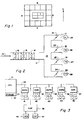
- FIG. 1 shows the floor plan of one floor of a typical building in which the present system can be used.
- This floor plan shows a plurality of exterior zones, i.e. zones which have at least one wall forming the outside perimeter of the building, of which zones E face to the east, zones N face to the north, zones W face to the west, and zones S face to the south.
- zones E face to the east
- zones N face to the north
- zones W face to the west
- zones S face to the south.
- there are a plurality of interior zones I which do not have any walls forming the outside perimeter of the building.
- FIG. 2 shows a fan system for supplying one or more of the zones N, E, S, W or I as shown in Figure 1.
- the fan system shown in Figure 2 can comprise the air conditioning system which is being controlled by the present control system.
- the fan system includes supply air duct 11 having therein heating coil 12, cooling coil 13 and fan supply 14.
- the heating coil 12 is supplied with hot water from a boiler in order to heat the air flowing through supply duct 11 and being delivered to the zone.
- Cooling coil 13 is supplied with chilled water from a chiller under control of various water pumps, valves and temperature controllers in order to cool the air moving through supply duct 11.
- Fan supply 14 is a fan which drives the air from inlet 15 to discharge air duct 16 so that the air can be supplied to the zone or zones supplied by the fan system shown in Figure 2.
- the fan system or air conditioning system shown in Figure 2 is comprised of a heating coil, a cooling coil and a fan
- additional or alternative equipment can be included within an air conditioning system.
- the air conditioning system may include pumps, valves , chillers, furnaces, supply fans, return fans and/or secondary chilled water pumps.
- the air in discharge air duct 16 is supplied to various diffusers 17, 18, 19 and 20 as controlled by corresponding dampers 21, 22, 23 and 24.
- One or more space temperature sensors can be included in the zone or zones supplied by discharge air duct 16 and may include space temperature sensors 25, 26, 27 and 28.
- the control system for controlling the air conditioning system shown in Figure 2 is shown in Figure 3.
- This control system includes a central processing unit 31 having a storage unit 32 associated therewith.
- CPU 31 communicates with remote data gathering panels (DGPs) 33, 34, 35, 36, 37 and 38 over a common communication channel 39.
- DGPs remote data gathering panels
- Remote data gathering panel (DGP) 33 is shown having a plurality of space temperature inputs 41 monitoring the zone or zones on the north side of the building, data gathering panel 34 is connected to a plurality of input space temperature sensors 42 for monitoring the space temperatures of the zone or zones on the east side of the building, DGP 35 is connected to a plurality of input temperature sensors 43 for sensing the temperature of the zone or zones on the south side of the floor shown in Figure 1, data gathering panel 36 is connected to a plurality of input space temperature sensors 44 for sensing the space temperature at various points on the west side of the building, and data gathering panel 37 is connected to a plurality of input space temperature sensors 45 for sensing the space temperature at various points in the interior zone or zones as shown in Figure 1. Additionally, data gathering panel 38 is connected to have an output for turning the air conditioning system 46, as represented by Figure 2, on and off and has as an input an outdoor air temperature sensor 47.
- the control system shown in Figure 3 may be any of the Delta automated building control systems manufactured by Honeywell Inc.
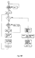
- drift rate is defined as the rate of temperature change of an occupied space in a building during the time when the heating/cooling equipment (e.g., fan system) is turned off. Drift rate is calculated in units of degrees per minute. Because the drift rate must be determined during the off time of the air conditioning equipment, the system of Figure 3 as shown in Figure 4A will enter the routine at the time that the optimum stop command is issued. At this point, the air conditioning system will be turned off.
- Central processing unit 31 of Figure 3 will then determine the space temperature for each of the zones 1 through X where X is the maximum number of zones controlled by the system shown in Figure 3. In the case where a zone has plural space temperature sensors associated therewith, central processing unit 31 will average the outputs from the plural space temperature sensors to derive the average space temperature for that zone. These space temperatures TEMP1 for each zone, the time TIME1 at which these measurements are taken and the outdoor air temperature are all stored in memory 32. The outdoor air temperature and the space temperature become the historic outdoor air temperature and space temperature which are then used in calculating the lead time on the next subsequent day on which an optimum stop procedure is to be performed.
- Dead time is defined as the response time of the zone space temperature to the air conditioning system shutdown.
- the dead time for a temperature zone operating in the heating mode is the amount of time between boiler shutdown and the zone temperature response in a negative direction.
- the zone space temperature will increase, peak, and assume a final negative slope. The dead time ends when this negative slope is assumed.
- a predetermined amount of time is then waited.
- the system may be arranged to wait 60 minutes before the space temperatures are next sensed.
- the space temperatures are sensed for each zone with average space temperatures being used for the zones having plural space temperature sensors.
- These second space temperatures TEMP2 are stored in memory 32 and the time TIME2 at which these second space temperature determinations are made is also stored in storage 32.
- drift rate is the change in space temperature over an amount of time T in which the air conditioning system is off in order to determine the magnitude of temperature drift during the off time. Since the drift rates of the zones may be different for each of the different types of zones, the drift rate must be calculated for each zone.
- variable A is set at 1 and a test is made to determine whether A has exceeded X, the number of zones of the system. If A has not exceeded X, the system will then determine if the fan is off. If the fan is not off at this 60 minute interval, the system will assume that a restart has occurred during the optimum stop time.
- the drift rate calculation will not be performed and the stored current drift rate value and temperatures will not be substituted for the new readings and the next lead time calculation will use the existing drift rate as the historical drift rate.
- the fan is restarted after an optimum stop command but before end of occupancy, it is presumed that a manual command or another energy management program having higher priority than the optimum stop program has superseded the optimum stop command. Thus, if the fan has been restarted during the optimum stop period, the optimum stop program will not attempt to restop the fan system.
- DR TEMP2 - TEMP1 TIME2 - TIME1
- TEMP1 is the average space temperature for zone A at the beginning of the drift rate time
- TEMP2 is the average zone temperature for the zone at the end of the drift time
- TIME1 is the time at which the drift time begins
- TIME2 is the time at which the drift time ends.
- the drift rate and dead time for zone A at this point is then stored in memory 32 as the historic drift rate for this zone and replaces the drift rate and dead time for zone A which had been stored in memory 32.
- the value 1 is added to the value of A and the system next tests to determine whether or not the drift rate for all zones has been calculated. If not, the system keeps making calculations until the drift rate for all zones have been calculated, at which time the routine proceeds to point A.
- Central processing unit 31 does not proceed beyond point A until one hour before the end of occupancy for the next day during which an optimum stop routine is to be performed.
- This one hour selection is arbitrary and can be any amount of desired time. Because of fresh air and other requirements for buildings, the amount of optimum stop time cannot be too great. Accordingly, a maximum limit must be imposed on the amount of optimum stop time during which the air conditioning is shut down prior to end of occupancy.
- the system automatically imposes a one hour maximum limit for the optimum stop time during which the air conditioning system is shut down prior to end of occupancy.
- the system periodically tests to determine whether or not actual time is within one hour of the end of occupancy time. If not, the system waits and keeps testing. Once the time is within one hour of the occupancy end time, the value A is again set to 1 and a test is made to determine whether or not A has exceeded X, the number of zones controlled by the system shown in Figure 3.
- the first step once A has been set to 1 and is tested to see whether it exceeds the value X, is to determine whether a positive value or a negative value of the historical drift rate is to be used. To make this determination requires that the current mode (heating or cooling) for each zone be identified. If the zone is an interior zone, the zone must always be in the cooling mode and no further tests are necessary. This is because an interior zone always represents a cooling load to the system. For exterior zones, i.e. the north zones, east zones, south zones and west zones for the floor plan shown in Figure 1, one way to determine whether or not the system is in the heating or cooling mode is to sample the outdoor air temperature. If the outdoor air temperature is equal to or exceeds 18°C, then all zones are in cooling and no further tests are necessary. If the outdoor air temperature is less than 18°C, then the average space temperature for each zone must be compared to the comfort range midpoint for that zone.
- a comfort range is the range in which space temperature is allowed to drift in order to maintain comfortable temperatures within the zone.
- a comfort range is established as an energy savings procedure in order to maintain air conditioning systems off or at minimum energy consumption as long as the space temperature is within the comfort range established for that zone. For example, it may be determined that as long as the space temperature is within the range of 20°C as a minimum and 25°C as a maximum, the air conditioning system will not attempt to adjust the space temperature.
- the zone is in cooling but if the average space temperature is less than the midpoint of the comfort range then the zone is in heating. If the zone is in cooling, then the positive drift rate is used as the historical drift rate but if the zone is in heating, then the negative drift rate is used as the historical drift rate.
- the drift rate for the current day will now be calculated based upon the drift rate which was determined for the previous day and stored as the historical drift rate, i.e. the drift rate that was determined for each zone using the procedure shown in Figure 4A.
- the temperature margin is calculated for each zone. This temperature margin is the absolute difference between the average zone temperature and the appropriate comfort limit which, for zones in heating, is the low comfort limit and for zones in cooling is the high comfort limit.
- the value of A is incremented by 1 and a test is made to determine whether or not the value of A exceeds X. If not, the lead time for each of the other zones is determined. Once the lead times for all zones has been determined, the shortest lead time is then selected because the shortest lead time represents the zone requiring the most air conditioning treatment. The optimum stop time is then determined by subtracting from the occupancy end time the shortest lead time. Once the stop time is reached, the optimum stop command is initiated. The system will store the current drift rate and dead time as the historical drift rate for the next day's calculations. Then, it will store the average space temperatures as the historic space temperatures and the outdoor air temperature as the historic outdoor air temperature for the next day's determinations.
Landscapes
- Engineering & Computer Science (AREA)
- Chemical & Material Sciences (AREA)
- Combustion & Propulsion (AREA)
- Mechanical Engineering (AREA)
- General Engineering & Computer Science (AREA)
- Physics & Mathematics (AREA)
- Signal Processing (AREA)
- Fuzzy Systems (AREA)
- Mathematical Physics (AREA)
- Human Computer Interaction (AREA)
- General Physics & Mathematics (AREA)
- Automation & Control Theory (AREA)
- Air Conditioning Control Device (AREA)
Description
- The present invention relates to an apparatus according to the preamble of one of the independent claims.
- Such an apparatus is e.g. known from US-A 4 475 685. Furtheron EP-A- 111 410 discloses a space temperature control system serving to determine optimum start and/or stop times for a heating or cooling unit where the start and/or stop times are based upon sensed previous deviations between desired and actual times that the space reached a desired level.
- Most control systems which control the temperature of commercial buildings today have various energy management functions which the control systems can perform. For example, the setpoint temperature within the building can be set up during summer month and set back during winter month when the building is not occupied in order to reduce the cost of running the temperature control system during times of non-occupancy. Together with the set up and set back function, the systems can perform an optimum start function in which the temperature control system is reenergized for an amount of time calculated to bring the space temperature within the comfort range for the building by the start of occupancy. In addition, typical systems will also provide an optimum stop function in which the temperature control system is shut off for a period of time prior to end of occupancy, this period of time designed to allow the space temperature to drift within the comfort range but not drift beyond the comfort range before the end of occupancy.
- Prior optimum start and optimum stop systems of this nature have relied upon outdoor air temperature to determine the amount of lead time necessary in performing the optimum start/stop functions. For example, during the heating months, the colder the outdoor air temperature, the more lead time is necessary during an optimum start function and the less lead time is allowed during the optimum stop function to make sure that during the entire period of occupancy, the space temperature is within the desired comfort range. The comfort range is defined here as the range established between the minimum allowable comfortable space temperature and the maximum allowable comfortable space temperature. The use of outdoor air temperature by itself to determine the lead time for use in optimum start/stop functions is not ideal because each building, because of its construction and because of external factors other than outdoor temperature, such as wind and solar radiation, do not have the same heat loss for the same outdoor air temperature.
- Thus, optimum start/stop functions have been developed to use space temperature drift rate in order to determine the lead time (see US-A 4 172 555). The space temperature drift rate is determined in such systems by controlling the temperature control system at its off state for the optimum stop function and at its on state for the optimum start function and for then dividing the temperature swing while the temperature control system is in this state by the amount of time that the temperature control system is in that state. For example, for an optimum start function and during winter months, the temperature control system is turned on at some time during the set back period and the temperature increase is then divided by the amount of time spanning that temperature increase in order to calculate drift rate which then can be used to determine the optimum start time. On the other hand, during winter months, the temperature control system can be turned off and the amount of temperature drift during that off time is divided by the amount of off time in order to determine the drift rate usable in optimum stop functions.
- This approach, however, requires the temperature control system to be artificially turned on or off in order to determine drift rate usable in the optimum start/stop functions. Moreover, prior systems have tended to be inaccurate because they rely either upon only space temperature or only upon outdoor air temperature.
- It is therefor the object of the present invention to devise an apparatus for determining optimum start/stop time of a temperature control system which is more accurate than the above indicated apparatus according to US-A 4 475 685. This object is achieved according to the features of the independent claims. Further advantageous embodiments of the apparatus may be taken from the dependent claims.
- Basically the present invention provides an apparatus which utilizes besides temperature drift a dead time of the system in order to determine the optimum lead time as modified by the outdoor air temperature.
- These and other features and advantages will become more apparent from a detailed consideration of the invention when taken in conjunction with the drawings in which:
- Figure 1 shows a floor plan of a typical commercial building having exterior zones such as north facing zones N, east facing zones E, south facing zones S and west facing zones W, and interior zones I;
- Figure 2 shows a fan system which can supply air conditioned air to each of the zones shown in Figure 1;
- Figure 3 shows the controller which can be used to control the air conditioning fan system of Figure 2; and,
- Figures 4A-4B show in flow chart form the way in which the control system of Figure 3 controls the air conditioning fan system.
- The present invention can be used in systems of any sizes for controlling the heating and/or cooling plants (air conditioning systems) of any sized buildings. Those skilled in the art will perceive that the present invention could be used to determine either optimum start or stop times. Only the computation of stop times will be discussed herein. For purposes of illustration, Figure 1 shows the floor plan of one floor of a typical building in which the present system can be used. This floor plan shows a plurality of exterior zones, i.e. zones which have at least one wall forming the outside perimeter of the building, of which zones E face to the east, zones N face to the north, zones W face to the west, and zones S face to the south. Also, there are a plurality of interior zones I which do not have any walls forming the outside perimeter of the building.
- Figure 2 shows a fan system for supplying one or more of the zones N, E, S, W or I as shown in Figure 1. For purposes of the present discussion, the fan system shown in Figure 2 can comprise the air conditioning system which is being controlled by the present control system. As shown in Figure 2, the fan system includes supply air duct 11 having therein
heating coil 12,cooling coil 13 andfan supply 14. Theheating coil 12 is supplied with hot water from a boiler in order to heat the air flowing through supply duct 11 and being delivered to the zone.Cooling coil 13 is supplied with chilled water from a chiller under control of various water pumps, valves and temperature controllers in order to cool the air moving through supply duct 11.Fan supply 14 is a fan which drives the air from inlet 15 to dischargeair duct 16 so that the air can be supplied to the zone or zones supplied by the fan system shown in Figure 2. - Although the fan system or air conditioning system shown in Figure 2 is comprised of a heating coil, a cooling coil and a fan, additional or alternative equipment can be included within an air conditioning system. For example, the air conditioning system may include pumps, valves , chillers, furnaces, supply fans, return fans and/or secondary chilled water pumps.
- As shown in Figure 2, the air in
discharge air duct 16 is supplied tovarious diffusers corresponding dampers discharge air duct 16 and may includespace temperature sensors 25, 26, 27 and 28. - The control system for controlling the air conditioning system shown in Figure 2 is shown in Figure 3. This control system includes a
central processing unit 31 having astorage unit 32 associated therewith.CPU 31 communicates with remote data gathering panels (DGPs) 33, 34, 35, 36, 37 and 38 over acommon communication channel 39. Remote data gathering panel (DGP) 33 is shown having a plurality ofspace temperature inputs 41 monitoring the zone or zones on the north side of the building,data gathering panel 34 is connected to a plurality of inputspace temperature sensors 42 for monitoring the space temperatures of the zone or zones on the east side of the building, DGP 35 is connected to a plurality ofinput temperature sensors 43 for sensing the temperature of the zone or zones on the south side of the floor shown in Figure 1,data gathering panel 36 is connected to a plurality of inputspace temperature sensors 44 for sensing the space temperature at various points on the west side of the building, anddata gathering panel 37 is connected to a plurality of inputspace temperature sensors 45 for sensing the space temperature at various points in the interior zone or zones as shown in Figure 1. Additionally,data gathering panel 38 is connected to have an output for turning theair conditioning system 46, as represented by Figure 2, on and off and has as an input an outdoorair temperature sensor 47. The control system shown in Figure 3 may be any of the Delta automated building control systems manufactured by Honeywell Inc. - Upon initial start up of the system shown in Figure 3, the
central processing unit 31 will for the first day assume a predetermined drift rate which will result in essentially a 0 lead time for that day. Thus, the air conditioning system is not energized until end of occupancy. For purposes of optimum stop calculations, drift rate is defined as the rate of temperature change of an occupied space in a building during the time when the heating/cooling equipment (e.g., fan system) is turned off. Drift rate is calculated in units of degrees per minute. Because the drift rate must be determined during the off time of the air conditioning equipment, the system of Figure 3 as shown in Figure 4A will enter the routine at the time that the optimum stop command is issued. At this point, the air conditioning system will be turned off. -
Central processing unit 31 of Figure 3 will then determine the space temperature for each of thezones 1 through X where X is the maximum number of zones controlled by the system shown in Figure 3. In the case where a zone has plural space temperature sensors associated therewith,central processing unit 31 will average the outputs from the plural space temperature sensors to derive the average space temperature for that zone. These space temperatures TEMP1 for each zone, the time TIME1 at which these measurements are taken and the outdoor air temperature are all stored inmemory 32. The outdoor air temperature and the space temperature become the historic outdoor air temperature and space temperature which are then used in calculating the lead time on the next subsequent day on which an optimum stop procedure is to be performed. - After the air conditioning system is stopped dead time is determined for each temperature zone. Dead time is defined as the response time of the zone space temperature to the air conditioning system shutdown. For example, the dead time for a temperature zone operating in the heating mode is the amount of time between boiler shutdown and the zone temperature response in a negative direction. Typically during the dead time in such a system the zone space temperature will increase, peak, and assume a final negative slope. The dead time ends when this negative slope is assumed.
- A predetermined amount of time is then waited. For example, the system may be arranged to wait 60 minutes before the space temperatures are next sensed. After that predetermined amount of time, the space temperatures are sensed for each zone with average space temperatures being used for the zones having plural space temperature sensors. These second space temperatures TEMP2 are stored in
memory 32 and the time TIME2 at which these second space temperature determinations are made is also stored instorage 32. - As mentioned, drift rate is the change in space temperature over an amount of time T in which the air conditioning system is off in order to determine the magnitude of temperature drift during the off time. Since the drift rates of the zones may be different for each of the different types of zones, the drift rate must be calculated for each zone. Thus, variable A is set at 1 and a test is made to determine whether A has exceeded X, the number of zones of the system. If A has not exceeded X, the system will then determine if the fan is off. If the fan is not off at this 60 minute interval, the system will assume that a restart has occurred during the optimum stop time. As a result, the drift rate calculation will not be performed and the stored current drift rate value and temperatures will not be substituted for the new readings and the next lead time calculation will use the existing drift rate as the historical drift rate. It should be noted that if the fan is restarted after an optimum stop command but before end of occupancy, it is presumed that a manual command or another energy management program having higher priority than the optimum stop program has superseded the optimum stop command. Thus, if the fan has been restarted during the optimum stop period, the optimum stop program will not attempt to restop the fan system.
- If, however, the fan of zone A is off, the system will determine the drift rate for zone A using the following equation:

where TEMP1 is the average space temperature for zone A at the beginning of the drift rate time, TEMP2 is the average zone temperature for the zone at the end of the drift time, TIME1 is the time at which the drift time begins and TIME2 is the time at which the drift time ends. As can be seen, if the drift rate is positive, the drift is up and if the drift rate is negative, the drift is down. If the drift rate is 0, no load exists. - The drift rate and dead time for zone A at this point is then stored in
memory 32 as the historic drift rate for this zone and replaces the drift rate and dead time for zone A which had been stored inmemory 32. Thevalue 1 is added to the value of A and the system next tests to determine whether or not the drift rate for all zones has been calculated. If not, the system keeps making calculations until the drift rate for all zones have been calculated, at which time the routine proceeds to point A. -
Central processing unit 31 does not proceed beyond point A until one hour before the end of occupancy for the next day during which an optimum stop routine is to be performed. This one hour selection is arbitrary and can be any amount of desired time. Because of fresh air and other requirements for buildings, the amount of optimum stop time cannot be too great. Accordingly, a maximum limit must be imposed on the amount of optimum stop time during which the air conditioning is shut down prior to end of occupancy. By delaying the calculation of lead time until one hour before end of occupancy, the system automatically imposes a one hour maximum limit for the optimum stop time during which the air conditioning system is shut down prior to end of occupancy. Thus, the system periodically tests to determine whether or not actual time is within one hour of the end of occupancy time. If not, the system waits and keeps testing. Once the time is within one hour of the occupancy end time, the value A is again set to 1 and a test is made to determine whether or not A has exceeded X, the number of zones controlled by the system shown in Figure 3. - The first step once A has been set to 1 and is tested to see whether it exceeds the value X, is to determine whether a positive value or a negative value of the historical drift rate is to be used. To make this determination requires that the current mode (heating or cooling) for each zone be identified. If the zone is an interior zone, the zone must always be in the cooling mode and no further tests are necessary. This is because an interior zone always represents a cooling load to the system. For exterior zones, i.e. the north zones, east zones, south zones and west zones for the floor plan shown in Figure 1, one way to determine whether or not the system is in the heating or cooling mode is to sample the outdoor air temperature. If the outdoor air temperature is equal to or exceeds 18°C, then all zones are in cooling and no further tests are necessary. If the outdoor air temperature is less than 18°C, then the average space temperature for each zone must be compared to the comfort range midpoint for that zone.
- A comfort range is the range in which space temperature is allowed to drift in order to maintain comfortable temperatures within the zone. A comfort range is established as an energy savings procedure in order to maintain air conditioning systems off or at minimum energy consumption as long as the space temperature is within the comfort range established for that zone. For example, it may be determined that as long as the space temperature is within the range of 20°C as a minimum and 25°C as a maximum, the air conditioning system will not attempt to adjust the space temperature.
- If the average space temperature is equal to or exceeds the midpoint of the comfort range, then the zone is in cooling but if the average space temperature is less than the midpoint of the comfort range then the zone is in heating. If the zone is in cooling, then the positive drift rate is used as the historical drift rate but if the zone is in heating, then the negative drift rate is used as the historical drift rate.
- The drift rate for the current day will now be calculated based upon the drift rate which was determined for the previous day and stored as the historical drift rate, i.e. the drift rate that was determined for each zone using the procedure shown in Figure 4A. The current drift rate, DRt, and dead time, DTt, can then be determined by the equation:


where STt is the current day's average zone temperature for the zone under consideration, OATt is the current day's outdoor air temperature, STh is the historical average zone temperature from the previous day, OATh is the historical outdoor air temperature from the previous day, and DTh is the historical dead time from the previous day. - Lead time for zone A is then calculated using the following equation:

where TM is the temperature margin, DRt is the absolute value of the drift rate, and DTt is the dead time for zone A which was just calculated for the current day. The temperature margin is calculated for each zone. This temperature margin is the absolute difference between the average zone temperature and the appropriate comfort limit which, for zones in heating, is the low comfort limit and for zones in cooling is the high comfort limit. - The value of A is incremented by 1 and a test is made to determine whether or not the value of A exceeds X. If not, the lead time for each of the other zones is determined. Once the lead times for all zones has been determined, the shortest lead time is then selected because the shortest lead time represents the zone requiring the most air conditioning treatment. The optimum stop time is then determined by subtracting from the occupancy end time the shortest lead time. Once the stop time is reached, the optimum stop command is initiated. The system will store the current drift rate and dead time as the historical drift rate for the next day's calculations. Then, it will store the average space temperatures as the historic space temperatures and the outdoor air temperature as the historic outdoor air temperature for the next day's determinations.
- If the drift rate is 0, lead time becomes maximum and need not be calculated.
Claims (5)
- Apparatus for determining the optimum stop time of a temperature control system within a building so that energy can be conserved by shutting down the temperature control system an amount of lead time prior to the end of occupancy of said building wherein said amount of lead time is arranged to confine space temperature within a comfort range defined by upper and lower comfort limit temperatures as said space temperature drifts during said amount of lead time dependent upon the temperature drift rate and the outdoor air temperature, said apparatus comprising:
space temperature sensing means (25,26,27 or 28) arranged to sense space temperature within said building,
outdoor air temperature sensing means (47) arranged to sense outdoor air temperature external to the building, and
controller means (31) connected to said space temperature sensing means and said outdoor air temperature sensing means, said controller means (31,32) serving to determine temperature drift rate within said building and to turn off said temperature control system before the end of occupancy of the building by said amount of lead time,
characterized in that said amount of lead time (TL) is calculated using the following equation: TM is the temperature margin, i.e. the absolute difference between the average space temperature and the relevant comfort limit temperature,DRt is the absolute value of the drift rate for the current day andDTt is the dead time for the current day,with the dead time being the amount of time between shut down of the temperature control system and a space temperature response in a negative direction in the case of the system operating in the heating mode, or a positive direction in the case of the system operating in the cooling mode,
whereat the drift rate (DRt) for the current day is calculated using the following equation: STt is the current day's average space temperature,OATt is the current day's outdoor air temperature,STh is the hystorical average space temperature from the previous day,OATh is the hystorical outdoor air temperature from the previous day, andDRh is the hystorical drift rate from the previous day, andwhereat the dead time (DTt) for the current day is calculated using the following equation:
 STt, OATt, STh and OATh are the temperatures as indicated above, andDTh is the historical dead time from the previous day.
 - Apparatus for determining the optimum start time of a temperature control system within a building so that energy can be conserved by starting the temperature control system an optimum amount of lead time prior to the start of occupancy wherein said amount of lead time, dependent upon the temperature drift rate and the outdoor air temperature, is arranged to bring said space temperature to within a comfort range defined by upper and lower comfort limit temperatures by said start of occupancy, said apparatus comprising:
space temperature sensing means (25,26,27 or 28) arranged to sense space temperature within said building,
outdoor air temperature sensing means (47) arranged to sense outdoor air temperature external to the building, and
controller mean (31) connected to said space temperature sensing means and said outdoor air temperature sensing means,
said controller means (31,32) serving to determine temperature drift rate within said building and to start said temperature control system an amount of lead time prior to the start of building occupancy,
characterized in that said amount of lead time (LT) is calculated using the following equation: TM is the temperature margin, i.e. the absolute difference between the average space temperature and the relevant comfort limit temperature,DRt is the absolute value of the drift rate for the current day andDTt is the dead time for the current day,with the dead time being the amount of time between start of the temperature control system and a space temperature response in a positive direction in the case of the system operating in the heating mode, or a negative direction in the case of the system operating in the cooling mode,
whereat the drift rate (DRt) for the current day is calculated using the following equation: STt is the current day's average space temperature,OATt is the current day's outdoor air temperature,STh is the hystorical average space temperature from the previous day,OATh is the hystorical outdoor air temperature from the previous day, andDRh is the hystorical drift rate from the previous day, andwhereat the dead time (DTt) for the current day is calculated using the following equation:
 STt, OATt, STh and OATh are the temperatures as indicated above, andDTh is the historical dead time from the previous day.
 - Apparatus according to claim 1 or 2, characterized in that said space temperature sensing means comprises space temperature sensors for each zone of a multizoned building for sensing the space temperature within its associated zone and that storage means (32) are provided to store a space temperature sensed by each space temperature sensor.
- Apparatus according to claim 3, characterized in that said controller means (31) comprises lead time determining means serving to determine an amount of lead time for each zone based upon a temperature drift rate and a dead time associated with each zone, the present outdoor air temperature and a historic outdoor air temperature.
- Apparatus according to claim 4, characterized in that said controller means (31) comprises stop/start means serving to determine the time at which the optimum stop/start time is to begin by subtracting from the end/begin of occupancy a lead time associated with the zone having the shortest lead time.
Applications Claiming Priority (2)
| Application Number | Priority Date | Filing Date | Title |
|---|---|---|---|
| US06/670,513 US4660759A (en) | 1984-11-13 | 1984-11-13 | Optimum start/stop dependent upon both space temperature and outdoor air temperature |
| US670513 | 1984-11-13 |
Publications (4)
| Publication Number | Publication Date |
|---|---|
| EP0182239A2 EP0182239A2 (en) | 1986-05-28 |
| EP0182239A3 EP0182239A3 (en) | 1987-12-09 |
| EP0182239B1 EP0182239B1 (en) | 1991-07-31 |
| EP0182239B2 true EP0182239B2 (en) | 1995-01-04 |
Family
ID=24690705
Family Applications (1)
| Application Number | Title | Priority Date | Filing Date |
|---|---|---|---|
| EP85114307A Expired - Lifetime EP0182239B2 (en) | 1984-11-13 | 1985-11-11 | System for determining the optimum start/stop time of a temperature control system |
Country Status (4)
| Country | Link |
|---|---|
| US (1) | US4660759A (en) |
| EP (1) | EP0182239B2 (en) |
| CA (1) | CA1249437A (en) |
| DE (1) | DE3583657D1 (en) |
Families Citing this family (20)
| Publication number | Priority date | Publication date | Assignee | Title |
|---|---|---|---|---|
| JPH0756390B2 (en) * | 1986-10-23 | 1995-06-14 | 株式会社東芝 | Air conditioner |
| US4784212A (en) * | 1986-11-21 | 1988-11-15 | Transmet Engineering, Inc. | Building perimeter thermal energy control system |
| JPH0816816B2 (en) * | 1989-11-10 | 1996-02-21 | 旭光学工業株式会社 | Heat roller temperature controller |
| US5025984A (en) * | 1990-06-22 | 1991-06-25 | Honeywell Inc. | Setback thermostat with recovery start time selected non-linearly |
| US5115967A (en) * | 1991-03-18 | 1992-05-26 | Wedekind Gilbert L | Method and apparatus for adaptively optimizing climate control energy consumption in a building |
| US5270952A (en) * | 1991-09-30 | 1993-12-14 | Honeywell Inc. | Self-adjusting recovery algorithm for a microprocessor-controlled setback thermostat |
| DE10361688B4 (en) * | 2003-12-30 | 2008-04-10 | Airbus Deutschland Gmbh | Device for controlling the supply air temperature of a passenger aircraft |
| US7099748B2 (en) * | 2004-06-29 | 2006-08-29 | York International Corp. | HVAC start-up control system and method |
| CA2641688C (en) * | 2006-02-10 | 2012-01-24 | Danfoss A/S | Method and system for controlling the climate in a house |
| US20080099570A1 (en) * | 2006-10-04 | 2008-05-01 | Steve Krebs | System and method for estimating temperature drift and drive curves |
| US20110231320A1 (en) * | 2009-12-22 | 2011-09-22 | Irving Gary W | Energy management systems and methods |
| EP2716989B1 (en) * | 2011-05-31 | 2017-03-22 | Mitsubishi Electric Corporation | Temperature adjusting system, air conditioning system, and control method |
| US9739496B2 (en) | 2013-12-16 | 2017-08-22 | Johnson Controls Technology Company | Systems and methods for estimating a return time |
| WO2015171796A1 (en) | 2014-05-07 | 2015-11-12 | Emerson Climate Technologies, Inc. | Heat pump and air conditioning grading systems and methods |
| US10352783B2 (en) | 2014-05-07 | 2019-07-16 | Emerson Climate Technologies, Inc. | Building envelope and interior grading systems and methods |
| CN106471316B (en) | 2014-05-07 | 2019-06-14 | 艾默生电气公司 | Heating, ventilation or air conditioning system classification system and method |
| CN107743569B (en) | 2015-06-08 | 2021-07-23 | 开利公司 | HVAC system start/stop control |
| CN105864956A (en) * | 2016-03-28 | 2016-08-17 | 广东美的暖通设备有限公司 | Drifting detection method for temperature sensor in air side heat exchanger, processor and air conditioner |
| CN113108438B (en) * | 2021-04-29 | 2022-05-06 | 珠海格力电器股份有限公司 | Air conditioner control method and device, storage medium and air conditioner |
| US11698204B1 (en) | 2022-06-05 | 2023-07-11 | Houshang Esmaili | Automation and optimization of fuel feed to heating elements of heating, ventilation, and air conditioning (HVAC) systems |
Family Cites Families (4)
| Publication number | Priority date | Publication date | Assignee | Title |
|---|---|---|---|---|
| US4172555A (en) * | 1978-05-22 | 1979-10-30 | Levine Michael R | Adaptive electronic thermostat |
| DE3024983C2 (en) * | 1980-07-02 | 1989-08-10 | Webasto-Werk W. Baier GmbH & Co, 8035 Gauting | Method and circuit arrangement for determining an amount of preheating energy |
| US4386649A (en) * | 1980-07-15 | 1983-06-07 | Nuclear Systems, Inc. | Programmable thermostatic control device |
| US4475685A (en) * | 1983-03-07 | 1984-10-09 | At&T Bell Laboratories | Control system for efficient intermittent operation of building HVAC equipment |
-
1984
- 1984-11-13 US US06/670,513 patent/US4660759A/en not_active Expired - Lifetime
-
1985
- 1985-10-07 CA CA000492399A patent/CA1249437A/en not_active Expired
- 1985-11-11 DE DE8585114307T patent/DE3583657D1/en not_active Expired - Fee Related
- 1985-11-11 EP EP85114307A patent/EP0182239B2/en not_active Expired - Lifetime
Also Published As
| Publication number | Publication date |
|---|---|
| EP0182239A3 (en) | 1987-12-09 |
| EP0182239B1 (en) | 1991-07-31 |
| EP0182239A2 (en) | 1986-05-28 |
| US4660759A (en) | 1987-04-28 |
| CA1249437A (en) | 1989-01-31 |
| DE3583657D1 (en) | 1991-09-05 |
Similar Documents
| Publication | Publication Date | Title |
|---|---|---|
| EP0182239B2 (en) | System for determining the optimum start/stop time of a temperature control system | |
| US4706882A (en) | Adaptive optimum start | |
| US4522336A (en) | Adaptive optimum start/stop control system | |
| US6478233B1 (en) | Thermal comfort controller having an integral energy savings estimator | |
| EP0001377B1 (en) | Apparatus and method for energy saving control of heating, ventilating and airconditioning (hvac) systems | |
| US4253153A (en) | Energy conservative control of terminal reheat heating, ventilating, and air conditioning (HVAC) systems | |
| EP2647921B1 (en) | HVAC controller for setting a setback value as a function from a recovery time | |
| US6186407B1 (en) | Humidity control based on an estimation using heating plant cycle, of inside window surface temperature | |
| EP0520827A2 (en) | Error based comfort zone controller | |
| JP3172959B2 (en) | Free cooling management device | |
| KR101187519B1 (en) | Air conditioning operating apparatus and air conditioning operating method | |
| EP2866117A1 (en) | Distributed adaptive and predictive heating control system and method | |
| EP3115703B1 (en) | Control of heating, ventilation, air conditioning | |
| US20080277488A1 (en) | Method for Controlling HVAC Systems | |
| US4523714A (en) | Heating apparatus | |
| US4136392A (en) | Load cycling with space temperature feedback | |
| JP2011043306A (en) | Energy saving air conditioning control system | |
| US4620668A (en) | Adaptive control system | |
| JP2002013776A (en) | Secondary system for district cooling and heating | |
| RU2196274C1 (en) | Method for automatic control of fuel consumption in district house heating system | |
| JP2602932B2 (en) | Heating and cooling timer | |
| EP0001378B1 (en) | Energy conservative control of terminal reheat heating, ventilating, and air conditioning (hvac) systems | |
| JP2007147094A (en) | Operation method of air conditioning equipment | |
| US20240318863A1 (en) | Automated sweat prevention for climate control systems | |
| JPS6338855A (en) | Temperature control method for heat storage tank |
Legal Events
| Date | Code | Title | Description |
|---|---|---|---|
| PUAI | Public reference made under article 153(3) epc to a published international application that has entered the european phase |
Free format text: ORIGINAL CODE: 0009012 |
|
| 17P | Request for examination filed |
Effective date: 19851203 |
|
| AK | Designated contracting states |
Kind code of ref document: A2 Designated state(s): DE GB |
|
| D17P | Request for examination filed (deleted) | ||
| PUAL | Search report despatched |
Free format text: ORIGINAL CODE: 0009013 |
|
| AK | Designated contracting states |
Kind code of ref document: A3 Designated state(s): DE GB |
|
| R17P | Request for examination filed (corrected) |
Effective date: 19880509 |
|
| 17Q | First examination report despatched |
Effective date: 19891020 |
|
| GRAA | (expected) grant |
Free format text: ORIGINAL CODE: 0009210 |
|
| AK | Designated contracting states |
Kind code of ref document: B1 Designated state(s): DE GB |
|
| REF | Corresponds to: |
Ref document number: 3583657 Country of ref document: DE Date of ref document: 19910905 |
|
| PLBI | Opposition filed |
Free format text: ORIGINAL CODE: 0009260 |
|
| 26 | Opposition filed |
Opponent name: SIEMENS AKTIENGESELLSCHAFT, BERLIN UND MUENCHEN Effective date: 19920429 |
|
| PUAH | Patent maintained in amended form |
Free format text: ORIGINAL CODE: 0009272 |
|
| STAA | Information on the status of an ep patent application or granted ep patent |
Free format text: STATUS: PATENT MAINTAINED AS AMENDED |
|
| 27A | Patent maintained in amended form |
Effective date: 19950104 |
|
| AK | Designated contracting states |
Kind code of ref document: B2 Designated state(s): DE GB |
|
| REG | Reference to a national code |
Ref country code: GB Ref legal event code: IF02 |
|
| PGFP | Annual fee paid to national office [announced via postgrant information from national office to epo] |
Ref country code: DE Payment date: 20031128 Year of fee payment: 19 |
|
| PGFP | Annual fee paid to national office [announced via postgrant information from national office to epo] |
Ref country code: GB Payment date: 20041004 Year of fee payment: 20 |
|
| PG25 | Lapsed in a contracting state [announced via postgrant information from national office to epo] |
Ref country code: DE Free format text: LAPSE BECAUSE OF NON-PAYMENT OF DUE FEES Effective date: 20050601 |
|
| PG25 | Lapsed in a contracting state [announced via postgrant information from national office to epo] |
Ref country code: GB Free format text: LAPSE BECAUSE OF EXPIRATION OF PROTECTION Effective date: 20051110 |
|
| REG | Reference to a national code |
Ref country code: GB Ref legal event code: PE20 |