EP0180731A1 - Power-operated chuck - Google Patents
Power-operated chuck Download PDFInfo
- Publication number
- EP0180731A1 EP0180731A1 EP19850110789 EP85110789A EP0180731A1 EP 0180731 A1 EP0180731 A1 EP 0180731A1 EP 19850110789 EP19850110789 EP 19850110789 EP 85110789 A EP85110789 A EP 85110789A EP 0180731 A1 EP0180731 A1 EP 0180731A1
- Authority
- EP
- European Patent Office
- Prior art keywords
- clamping
- chuck
- force
- signal
- arrangement according
- Prior art date
- Legal status (The legal status is an assumption and is not a legal conclusion. Google has not performed a legal analysis and makes no representation as to the accuracy of the status listed.)
- Granted
Links
Images


Classifications
-
- B—PERFORMING OPERATIONS; TRANSPORTING
- B23—MACHINE TOOLS; METAL-WORKING NOT OTHERWISE PROVIDED FOR
- B23B—TURNING; BORING
- B23B31/00—Chucks; Expansion mandrels; Adaptations thereof for remote control
- B23B31/02—Chucks
- B23B31/10—Chucks characterised by the retaining or gripping devices or their immediate operating means
- B23B31/12—Chucks with simultaneously-acting jaws, whether or not also individually adjustable
- B23B31/16—Chucks with simultaneously-acting jaws, whether or not also individually adjustable moving radially
- B23B31/16233—Jaws movement actuated by oblique surfaces of a coaxial control rod
-
- B—PERFORMING OPERATIONS; TRANSPORTING
- B23—MACHINE TOOLS; METAL-WORKING NOT OTHERWISE PROVIDED FOR
- B23Q—DETAILS, COMPONENTS, OR ACCESSORIES FOR MACHINE TOOLS, e.g. ARRANGEMENTS FOR COPYING OR CONTROLLING; MACHINE TOOLS IN GENERAL CHARACTERISED BY THE CONSTRUCTION OF PARTICULAR DETAILS OR COMPONENTS; COMBINATIONS OR ASSOCIATIONS OF METAL-WORKING MACHINES, NOT DIRECTED TO A PARTICULAR RESULT
- B23Q17/00—Arrangements for observing, indicating or measuring on machine tools
- B23Q17/002—Arrangements for observing, indicating or measuring on machine tools for indicating or measuring the holding action of work or tool holders
- B23Q17/005—Arrangements for observing, indicating or measuring on machine tools for indicating or measuring the holding action of work or tool holders by measuring a force, a pressure or a deformation
Definitions
- the invention relates to an arrangement for detecting the clamping force in a rotating power-operated chuck, which has radially guided in the chuck body and adjustable by a drive member located in the chuck jaws, with a arranged in the power flow between the drive member and at least one of the jaws, the size of this power flow proportional electrical clamping force signal generating clamping force sensor, and with a signal transmission device from the chuck to a stationary signal evaluation device.
- a chuck with such an arrangement is known from DE-OS 28 46 337, in which the clamping force transducer is arranged in the clamping jaw.
- the detection of the force flow serves to be able to determine changes in the clamping force transferred to the workpiece, which are caused, among other things, by centrifugal forces which act on the chuck parts participating in the power transmission, i.e. also on the clamping jaws, and can have a considerable influence, in particular at higher chuck speeds . Read the deviations registered in this way They can be made visible through display means, but can also be used for control purposes.
- the invention has for its object to provide an arrangement of the type mentioned in such a way that regardless of the radial position and the mass of the clamping jaws, the clamping force actually effective on the clamping surface of the clamping jaws, in particular thus on the workpiece, is detected.
- An arrangement achieving this object is characterized according to the invention by a centrifugal force generator which generates an electric centrifugal force signal proportional to the centrifugal force, the signal level of which can be adjusted for signal normalization, and by a subtractor or adder which is actually effective for determining the clamping surface of the clamping jaw
- the clamping force signal and the normalized centrifugal force signal are subtracted from each other in the case of external tension or added to one another in the case of internal tension.
- the progress achieved by the invention essentially consists in the fact that the centrifugal force signal, with appropriate normalization, corresponds to the centrifugal force effective on the parts between the clamping surface and the location of the clamping force measuring sensor and is therefore equal to the difference between that determined by the clamping force measuring sensor and that actually from the Clamping jaw transferred to the workpiece.
- the output of the subtractor or adder immediately provides a signal quantity that corresponds to the clamping force actually acting on the workpiece.
- the arrangement is thus advantageously equally well suited for external and internal clamping of a workpiece.
- the value of the actual clamping force or the centrifugal force component can then be displayed, if necessary by means of a downstream signal processing. This is, for. B.
- the centrifugal force signal can be used for automatic or hand-controlled readjustment of the clamping force during operation at working speed or, in contrast, at a reduced speed, or can be used in connection with safety circuits of the lathe.
- the centrifugal force sensor consists of a centrifugal weight guided radially adjustably in the chuck body and a centrifugal force sensor which detects its centrifugal force.
- This arrangement has the advantage that the quadratic dependence of the centrifugal force on the angular velocity or speed of the chuck is taken into account directly.
- An adjustable voltage divider for signal normalization is expediently connected downstream of the centrifugal force sensor. It is also recommended that the centrifugal weight is adjustably arranged on a lever which is pivotably mounted in the chuck body and acts on the centrifugal force sensor. The centrifugal weight can thus be adjusted independently of the arrangement of the centrifugal force sensor.
- the pivot axis of the lever can be arranged parallel to the chuck axis and the lever in a substantially tangential direction in the chuck body.
- the pivot axis of the lever is perpendicular to the chuck axis and the lever is in a direction substantially parallel to the chuck axis.
- an adjusting bolt which is displaceably guided parallel to the chuck axis is provided, the one free end of which for actuation by the clamping jaw from the chuck end surface protrudes and the other end is supported on the inside by a compression spring on the chuck body, that further the adjusting bolt has two radial projections between which the flyweight of the lever protrudes with positive locking, the adjusting bolt with its free end under the force of the compression spring provided on the clamping jaw Stop is present.
- the centrifugal weight on the lever is displaced by axial displacement of the adjusting bolt, so that the force acting on the centrifugal force sensor can be varied for the purpose of standardization at the same speed of the chuck. It is thus possible to standardize the centrifugal force component recorded by measurement with regard to the radial position and the mass of the clamping jaws.
- a parallel to the chuck axis, protruding from the chuck face, axially displaceable by a stop arranged on the clamping jaw is provided, which actuates a linear displacement sensor such as potentiometer, inductive displacement sensor or the like, which the centrifugal force sensor is connected downstream to normalize the centrifugal force signal.
- a linear displacement sensor such as potentiometer, inductive displacement sensor or the like
- the centrifugal force sensor is connected downstream to normalize the centrifugal force signal.
- the stop forms a control link for the adjusting bolt or pin that runs in the direction of adjustment of the clamping jaw. Because of the linear dependence of the centrifugal force on the radial position of the clamping jaw, the control link can run in a wedge shape in relation to the face of the chuck.
- the clamping is made up of a split jaw consisting of a base and top jaw bake the stop on the top jaw is provided, since the respective mass of the different top jaws can then be taken into account by appropriate arrangement of the stop. This is possible in particular because the distance between the control link and the face of the chuck depends on the shape and mass of the top jaw.
- the subtractor or adder is formed by an operational amplifier circuit arranged in the chuck body. This means that it is not necessary to transmit the measuring signals of the measuring sensors, which are in any case very small, but only the signal quantities that have already been processed and, as a rule, already amplified.
- a particularly interference-free signal transmission is given when the operational amplifier circuit is followed by a voltage-frequency converter, the output signal of which is fed to an encoder part of the signal transmission device arranged on the chuck.
- the measuring sensors can be designed in any way with regard to their measuring principle.
- the clamping force sensor and the centrifugal force sensor are designed as a displacement sensor that detects a change in length caused by the force.
- the displacement sensor be formed by strain gauges.
- the clamping force transducer can expediently record the force flow on the coupling piece.
- the clamping force transducer can be arranged in a recess on the outer surface of the coupling piece.
- the signal evaluation device forms a signal representing the actual clamping force on the clamping jaw and makes it available for use in controlling the lathe driving the chuck.
- the chuck body of the chuck is generally designated 1 and the clamping jaws, which are guided in a radially adjustable manner therein, are designated by 2.
- a chuck generally has three clamping jaws 2, which are in a non-positive and positive engagement with a drive member 1.3 for their radial adjustment, for example via wedge hooks 1.2.
- An axial adjustment of the drive member 1.3 consequently brings about a radial adjustment of the clamping jaws 2.
- the drive member 1.3 can be actuated in a manner known per se and therefore not described here in more detail by a clamping cylinder, the clamping piston of which is passed through the hollow lathe spindle via a drawbar or a draw tube can be connected to the drive member 1.3.
- a clamping force sensor 3 is arranged in the frictional connection between the drive member 1.3 and the clamping jaw 2, which detects the flow of force between the drive member 1.3 and the clamping jaw 2.
- a signal transmission device also not shown in the drawing, which consists of a transmitter part on the chuck, for. B. arranged in annular grooves 1.4 rotor coils and a stationary with respect to the chuck signal evaluation device.
- the chuck body 1 is provided with a centrifugal force sensor 4, which is formed by a centrifugal weight 7, which is guided in a radially adjustable manner in the chuck body 1, and a centrifugal force measuring sensor 6 which detects its centrifugal force.
- the centrifugal weight 7 can act directly on the centrifugal force sensor 6.
- the centrifugal weight 7, on the other hand is adjustably arranged on a lever 5 which is pivotably mounted in the chuck body 1 and has two arms.
- One arm 5.1 carries the centrifugal weight 7 adjustable in the longitudinal direction of the lever 5, while the other arm 5.2 acts on the centrifugal force sensor 6.
- the pivot axis 5.3 of the lever 5 runs parallel to the chuck axis 8, the lever 5 being arranged in the chuck body in a substantially tangential direction.
- the pivot axis 5.3 of the lever 5 runs perpendicular to the chuck axis 8 and the lever 5 in a direction essentially parallel to the chuck axis 8.
- this setting can also be made manually, for example, by means of marking grooves 9 provided on the lever arm 5.1, but in the embodiment of FIG. 1 by means of a potentiometer 20.
- an adjustment bolt 10 which is displaceably guided parallel to the chuck axis and whose free end 10.1 projects from the chuck end face 1.1 for actuation by the clamping jaw 2, is provided for adjusting the centrifugal weight 7.
- the adjusting bolt 10 has two radial projections 11, between which the centrifugal weight 7 of the lever 5 projects with a positive fit.
- the other ' end of the adjusting bolt 10 is supported on the inside via a compression spring 12 on the chuck body 1, as a result of which the adjusting bolt 10 bears with its free end 10.1 under the force of the compression spring 12 against a stop 13 provided on the clamping jaw 2.
- the stop surface 13.1 of the stop 13 is designed in the adjustment direction of the clamping jaw 2 as a control link 13.1, so that when the clamping jaw 2 is adjusted radially, the adjusting bolt 10 and with it the centrifugal weight 7 are axially displaced. Because of the linear dependence of the centrifugal force on the radial distance, the control link 13.1 can run essentially wedge-shaped in the adjustment direction of the clamping jaw 2 with respect to the chuck end face 1.1. In the case of split jaws 2 consisting of base jaw 2.2 and top jaw 2.3, the stop 13 is connected to the top jaw 2.3.
- a subtracting or adding element 19 which is only shown schematically in FIG. 8, is provided, which contains the signal of the clamping force measuring sensor 3 arranged in a bridge circuit and the normalized signal of the, adjusted via a potentiometer 20 Centrifugal force transducer 6 subtracted from one another when the chuck is externally tensioned or added to one another when the chucking tension is internal.
- the subtractor or adder 19 can also be part of a correspondingly switched operational amplifier 18 in a known manner
- a voltage-frequency converter optionally connected downstream of the operational amplifier 18, but not shown in the drawing, enables a particularly simple and interference-free transmission of the signal from the transmitter part on the chuck to the stationary signal evaluation device.
- the tension force transducer 3 is designed in a manner not shown as a displacement sensor in the form of a strain gauge that detects a change in length. If S p annbak- ken 2, in which the guide jaw 2.1 and the base jaw 2.2 can be uncoupled and positively connected to one another via a coupling piece 14 designed, for example, as a toothing bolt, the clamping force transducer 3 according to FIGS. 6 and 7 is arranged on the coupling piece 14.
- the tension force transducer 3 according to FIG. 6 can be arranged in a recess 15 on the outer surface of the coupling piece 14. However, there is also the possibility shown in FIG. 7 of arranging the clamping force measuring sensor 3 in a recess 16 of the adjusting ring 17, which adjusts the coupling piece 14 in the axial direction and against which the coupling piece 14 rests on the end face.
- the signal which is transmitted from the transmitter part to the stationary signal evaluation device and which reflects the operating clamping force actually occurring on the workpiece can finally be available in a manner not shown for use in controlling the lathe driving the chuck. Changes in the clamping force registered in this way, in particular their lowering below a predetermined value, can be used to indicate a necessary tool change or to shut down the machine. The height of the clamping force applied by the clamping cylinder can also be corrected.
Abstract
Description
Die Erfindung betrifft eine Anordnung zur Erfassung der Spannkraft bei einem umlaufenden kraftbetätigten Spannfutter, das radial im Futterkörper geführte und durch ein im Futterkörper befindliches Antriebsglied verstellbare Spannbacken aufweist, mit einem im Kraftfluß zwischen dem Antriebsglied und mindestens einer der Spannbacken angeordneten, ein der Größe dieses Kraftflusses proportionales elektrisches Spannkraftsignal erzeugenden Spannkraft-Meßaufnehmer, und mit einer Signalübertragungseinrichtung vom Spannfutter auf eine stationäre Signalauswerteeinrichtung.The invention relates to an arrangement for detecting the clamping force in a rotating power-operated chuck, which has radially guided in the chuck body and adjustable by a drive member located in the chuck jaws, with a arranged in the power flow between the drive member and at least one of the jaws, the size of this power flow proportional electrical clamping force signal generating clamping force sensor, and with a signal transmission device from the chuck to a stationary signal evaluation device.
Ein Spannfutter mit einer derartigen Anordnung ist aus der DE-OS 28 46 337 bekannt, bei welchem der Spannkraft-Meßaufnehmer in der Spannbacke angeordnet ist. Die Erfassung des Kraftflusses dient dazu, Änderungen der auf das Werkstück übertragenen Spannkraft ermitteln zu können, die unter anderem von Fliehkräften verursacht werden, die an den bei der Kraftübertragung teilnehmenden Futterteilen, also auch an den Spannbacken angreifen und insbesondere bei höheren Futterdrehzahlen erheblichen Einfluß haben können. Die so registrierten Abweichungen lassen sich durch Anzeigemittel sichtbar machen, können jedoch auch für Regelungszwecke benutzt werden.A chuck with such an arrangement is known from DE-OS 28 46 337, in which the clamping force transducer is arranged in the clamping jaw. The detection of the force flow serves to be able to determine changes in the clamping force transferred to the workpiece, which are caused, among other things, by centrifugal forces which act on the chuck parts participating in the power transmission, i.e. also on the clamping jaws, and can have a considerable influence, in particular at higher chuck speeds . Read the deviations registered in this way They can be made visible through display means, but can also be used for control purposes.
Jedoch bereitet es hierbei Schwierigkeiten, den Einfluß der Fliehkräfte auf die Meßwertbildung richtig.zu erfassen, da die Spannkraft-Meßaufnehmer in der Regel nicht unmittelbaran der am Werkstück zur Anlage kommenden Spannfläche der Spannbacke angeordnet sein können. Dies ist schon wegen der Empfindlichkeit der Spannkraft-Meßaufnehmer problematisch; darüber hinaus wäre wegen der elektrischen Zuleitungen zum Spannkraft-Meßaufnehmer der Austausch der Spannbacken erschwert. Wird daher die Spannkraft nicht unmittelbar an der am Werkstück zur Anlage kommenden Spannfläche der Spannbacke gemessen, so bleibt bei der Messung der Spannkraft der Fliehkraftanteil jener Massenteile unberücksichtigt, die sich im Kraftflußbereich zwischen der Spannfläche und dem Ort des Spannkraft-Meßaufnehmers befinden. Eine pauschale Berücksichtigung dieses Anteils ist wegen seiner Abhängigkeit von der radialen Stellung der Spannbacke und der jeweiligen Massenverteilung bei verschiedenen zur Anwendung kommenden Spannbacken nicht möglich, so daß erhebliche Abweichungen zwischen der am Spannkraft-Meßaufnehmer ermittelten und der tatsächlich am Werkstück angreifenden Spannkraft bestehen können.However, it is difficult here to correctly determine the influence of the centrifugal forces on the formation of the measured value, since the clamping force transducers cannot generally be arranged directly on the clamping surface of the clamping jaw coming into contact with the workpiece. This is problematic because of the sensitivity of the clamping force transducers; In addition, the exchange of the jaws would be difficult because of the electrical leads to the clamping force sensor. Therefore, if the clamping force is not measured directly on the clamping surface of the clamping jaw coming into contact with the workpiece, the measurement of the clamping force does not take into account the proportion of centrifugal force in those parts of the mass which are in the force flow range between the clamping surface and the location of the clamping force sensor. A general consideration of this proportion is not possible because of its dependence on the radial position of the clamping jaw and the respective mass distribution for different clamping jaws used, so that there may be considerable deviations between the clamping force transducer determined and the clamping force actually acting on the workpiece.
Der Erfindung liegt die Aufgabe zugrunde, eine Anordnung der eingangs genannten Art so auszubilden, daß unabhängig von der radialen Stellung und der Masse der Spannbacken die tatsächlich an der Spannfläche der Spannbacken, insbesondere also am Werkstück wirksame Spannkraft erfaßt wird.The invention has for its object to provide an arrangement of the type mentioned in such a way that regardless of the radial position and the mass of the clamping jaws, the clamping force actually effective on the clamping surface of the clamping jaws, in particular thus on the workpiece, is detected.
Eine diese Aufgabe lösende Anordnung ist nach der Erfindung gekennzeichnet durch einen Fliehkraftgeber, der ein der Fliehkraft proportionales elektrisches Fliehkraftsignal erzeugt, dessen Signalpegel zur Signalnormierung einstellbar ist, und durch ein Subtrahier- bzw. Addierglied, das zur Ermittlung der an der Spannfläche der Spannbacke tatsächlich wirksamen Spannkraft das Spannkraftsignal und das normierte Fliehkraftsignal bei Außenspannung voneinander subtrahiert bzw. bei Innenspannung zueinander addiert.An arrangement achieving this object is characterized according to the invention by a centrifugal force generator which generates an electric centrifugal force signal proportional to the centrifugal force, the signal level of which can be adjusted for signal normalization, and by a subtractor or adder which is actually effective for determining the clamping surface of the clamping jaw The clamping force signal and the normalized centrifugal force signal are subtracted from each other in the case of external tension or added to one another in the case of internal tension.
Der durch die Erfindung erreichte Fortschritt besteht im wesentlichen darin, daß das Fliehkraftsignal bei entsprechender Normierung der an den Teilen zwischen Spannfläche und Ort des Spannkraft-Meßaufnehmers wirksamen Fliehkraft entspricht und daher gleich dem Differenzbetrag ist zwischen der vom Spannkraft-Meßaufnehmer ermittelten und der tatsächlich von der Spannbacke auf das Werkstück übertragenen Kraft. Dabei stellt der Ausgang des Subtrahier- bzw. Addierglieds unmittelbar eine Signalgröße zur Verfügung, die der tatsächlich am Werkstück angreifenden Spannkraft entspricht. Die Anordnung ist somit ferner in vorteilhafter Weise für Außen- wie für Innenspannung eines Werkstücks in gleicher Weise gut geeignet. Der Wert der tatsächlichen Spannkraft oder auch des Fliehkraftanteils kann dann, gegebenenfalls mittels einer nachgeschalteten Signalverarbeitung zur Anzeige gebracht werden. Dadurch besteht z. B. die Möglichkeit, bei weiteren Spannvorgängen gleicher Art den Fliehkraftanteil bereits während des Spannvorgangs bei der Bemessung der Spannkraft kompensierend zu berücksichtigen. Ebenso kann das Fliehkraftsignal zur automatischen oder handgesteuerten Nachregelung der Spannkraft während des Betriebs bei Arbeitsdrehzahl oder auch bei demgegenüber verminderter Drehzahl herangezogen werden oder im Zusammenhang mit Sicherheitsschaltungen der Drehmaschine Verwendung finden.The progress achieved by the invention essentially consists in the fact that the centrifugal force signal, with appropriate normalization, corresponds to the centrifugal force effective on the parts between the clamping surface and the location of the clamping force measuring sensor and is therefore equal to the difference between that determined by the clamping force measuring sensor and that actually from the Clamping jaw transferred to the workpiece. The output of the subtractor or adder immediately provides a signal quantity that corresponds to the clamping force actually acting on the workpiece. The arrangement is thus advantageously equally well suited for external and internal clamping of a workpiece. The value of the actual clamping force or the centrifugal force component can then be displayed, if necessary by means of a downstream signal processing. This is, for. B. the possibility of further centrifugal forces of the same type, the centrifugal force already during the clamping process at the loading measurement of the clamping force must be taken into account to compensate. Likewise, the centrifugal force signal can be used for automatic or hand-controlled readjustment of the clamping force during operation at working speed or, in contrast, at a reduced speed, or can be used in connection with safety circuits of the lathe.
In bevorzugter Ausführungsform der Erfindung besteht der Fliehkraftgeber aus einem im Futterkörper radial verstellbar geführten Fliehgewicht und einem dessen Fliehkraft erfassenden Fliehkraft-Meßaufnehmer. Diese Anordnung hat den Vorteil, daß die quadratische Abhängigkeit der Fliehkraft von der Winkelgeschwindigkeit bzw. Drehzahl des Futters unmittelbar mitberücksichtigt wird. Zweckmäßigerweise ist dem Fliehkraft-Meßaufnehmer ein einstellbarer Spannungsteiler zur Signalnormierung nachgeschaltet. Weiter empfiehlt es sich, daß das Fliehgewicht verstellbar an einem schwenkbar im Futterkörper gelagerten, den Fliehkraft-Meßaufnehmer beaufschlagenden Hebel angeordnet ist. Somit kann die Verstellung des Fliehgewichts unabhängig von der Anordnung des Fliehkraft-Meßaufnehmers erfolgen. Die Schwenkachse des Hebels kann parallel zur FutterT achse und der Hebel in im wesentlichen tangentialer Richtung im Futterkörper angeordnet sein. Es besteht jedoch auch die Möglichkeit, daß die Schwenkachse des Hebels senkrecht zur Futterachse und der Hebel in zur Futterachse im wesentlichen paralleler Richtung verläuft. Dann empfiehlt es sich in bevorzugter Ausführungsform der Erfindung weiter, daß ein parallel zur Futterachse verschiebbar geführter Verstellbolzen vorgesehen ist, dessen eines freies Ende zur Betätigung durch die- Spannbacke aus der Futterstirnfläche vorsteht und dessen anderes Ende sich über eine Druckfeder am Futterkörper innenseitig abstützt, daß ferner der Verstellbolzen zwei Radialvorsprünge aufweist, zwischen die das Fliehgewicht des Hebels unter Formschluß vorsteht, wobei der Verstellbolzen mit seinem freien Ende unter der Kraft der Druckfeder einem an der Spannbacke vorgesehenen Anschlag anliegt. Auf diese Weise wird durch axiale Verschiebung des Verstellbolzens das Fliehgewicht auf dem Hebel verschoben, so daß zum Zwecke der Normierung bei gleicher Drehzahl des Spannfutters die auf den Fliehkraft-Meßaufnehmer wirkende Kraft variiert werden kann. Damit besteht die Möglichkeit, den meßtechnisch erfaßten Fliehkraftanteil bezüglich der radialen Lage und der Masse der Spannbacken zu normieren.In a preferred embodiment of the invention, the centrifugal force sensor consists of a centrifugal weight guided radially adjustably in the chuck body and a centrifugal force sensor which detects its centrifugal force. This arrangement has the advantage that the quadratic dependence of the centrifugal force on the angular velocity or speed of the chuck is taken into account directly. An adjustable voltage divider for signal normalization is expediently connected downstream of the centrifugal force sensor. It is also recommended that the centrifugal weight is adjustably arranged on a lever which is pivotably mounted in the chuck body and acts on the centrifugal force sensor. The centrifugal weight can thus be adjusted independently of the arrangement of the centrifugal force sensor. The pivot axis of the lever can be arranged parallel to the chuck axis and the lever in a substantially tangential direction in the chuck body. However, there is also the possibility that the pivot axis of the lever is perpendicular to the chuck axis and the lever is in a direction substantially parallel to the chuck axis. Then, in a preferred embodiment of the invention, it is further recommended that an adjusting bolt which is displaceably guided parallel to the chuck axis is provided, the one free end of which for actuation by the clamping jaw from the chuck end surface protrudes and the other end is supported on the inside by a compression spring on the chuck body, that further the adjusting bolt has two radial projections between which the flyweight of the lever protrudes with positive locking, the adjusting bolt with its free end under the force of the compression spring provided on the clamping jaw Stop is present. In this way, the centrifugal weight on the lever is displaced by axial displacement of the adjusting bolt, so that the force acting on the centrifugal force sensor can be varied for the purpose of standardization at the same speed of the chuck. It is thus possible to standardize the centrifugal force component recorded by measurement with regard to the radial position and the mass of the clamping jaws.
Es besteht jedoch auch die Möglichkeit, daß ein zur Futterachse paralleler, aus der Futterstirnfläche vorstehender, durch einen an der Spannbacke angeordneten Anschlag axial verschiebbarer Verstellstift vorgesehen ist, der einen linearen Weggeber wie Potentiometer, induktiven Weggeber oder dergl. betätigt, der dem Fliehkraft-Meßaufnehmer zur Normierung des Fliehkraftsignals nachgeschaltet ist. Dabei kann es sich zur Berücksichtigung der radialen Lage der Spannbacke empfehlen, daß der Anschlag eine in Verstellrichtung der Spannbacke verlaufende Steuerkulisse für den Verstellbolzen bzw. -stift bildet. Wegen der linearen Abhängigkeit der Fliehkraft von der radialen Lage der Spannbacke kann die Steuerkulisse gegenüber der Futterstirnfläche keilförmig verlaufen. Weiter ist es von Vorteil, wenn bei geteilt ausgebildeten, aus Grund- und Aufsatzbacke bestehenden Spannbacken der Anschlag an der Aufsatzbacke vorgesehen ist, da dann durch entsprechende Anordnung des Anschlags die jeweilige Masse der verschiedenen Aufsatzbacken berücksichtigt werden kann. Dies ist insbesondere dadurch möglich, daß der Abstand der Steuerkulisse von der Futterstirnfläche abhängig von der Form und Masse der Aufsatzbacke ist.However, there is also the possibility that a parallel to the chuck axis, protruding from the chuck face, axially displaceable by a stop arranged on the clamping jaw is provided, which actuates a linear displacement sensor such as potentiometer, inductive displacement sensor or the like, which the centrifugal force sensor is connected downstream to normalize the centrifugal force signal. To take into account the radial position of the clamping jaw, it can be recommended that the stop forms a control link for the adjusting bolt or pin that runs in the direction of adjustment of the clamping jaw. Because of the linear dependence of the centrifugal force on the radial position of the clamping jaw, the control link can run in a wedge shape in relation to the face of the chuck. It is also of advantage if the clamping is made up of a split jaw consisting of a base and top jaw bake the stop on the top jaw is provided, since the respective mass of the different top jaws can then be taken into account by appropriate arrangement of the stop. This is possible in particular because the distance between the control link and the face of the chuck depends on the shape and mass of the top jaw.
Um die Signalübertragung vom Spannfutter zur stationären Signalauswerteeinrichtung einfach zu gestalten, empfiehlt es sich, daß das Subtrahier- bzw. Addierglied von einer im Futterkörper angeordneten Operationsverstärkerschaltung gebildet ist. Damit müssen nicht die ohnehin sehr kleinen Meßsignale der Meßaufnehmer, sondern nur die bereits aufbereiteten und in der Regel auch schon verstärkten Signalgrößen übertragen werden. Eine besonders störungsfreie Signalübertragung ist insbesondere dann gegeben, wenn der Operationsverstärkerschaltung ein Spannungs-Frequenz-Wandler nachgeschaltet ist, dessen Ausgangssignal einem am Spannfutter angeordneten Geberteil der Signalübertragungseinrichtung zugeführt wird.In order to make the signal transmission from the chuck to the stationary signal evaluation device simple, it is recommended that the subtractor or adder is formed by an operational amplifier circuit arranged in the chuck body. This means that it is not necessary to transmit the measuring signals of the measuring sensors, which are in any case very small, but only the signal quantities that have already been processed and, as a rule, already amplified. A particularly interference-free signal transmission is given when the operational amplifier circuit is followed by a voltage-frequency converter, the output signal of which is fed to an encoder part of the signal transmission device arranged on the chuck.
Die Meßaufnehmer können, abhängig von ihrem jeweiligen Anbrhgungsort,hinsichtlich ihres Meßprinzips bebeliebig gestaltet sein. In der Regel wird es jedoch vorteilhaft sein, wenn der Spannkraft--und der Fliehkraft-Meßaufnehmer als ein eine von der Kraft bewirkte Längenveränderung erfassender Wegaufnehmer ausgebildet ist. Insbesondere empfiehlt es sich, daß der Wegaufnehmer von Dehnungsmeßstreifen gebildet ist. Bei geteilt ausgebildeten und durch ein Kupplungsstück lös- und versetzbar miteinander verbundenen Spannbacken kann zweckmäßigerweise der Spannkraft-Meßaufnehmer den Kraftfluß am Kupplungsstück erfassen. Dabei kann der Spannkraft-Meßaufnehmer in einer Ausnehmung an der Mantelfläche des Kupplungsstücks angeordnet sein.Depending on their respective mounting location, the measuring sensors can be designed in any way with regard to their measuring principle. As a rule, however, it will be advantageous if the clamping force sensor and the centrifugal force sensor are designed as a displacement sensor that detects a change in length caused by the force. In particular, it is recommended that the displacement sensor be formed by strain gauges. In the case of split training and releasably and releasably connected by a coupling piece The clamping force transducer can expediently record the force flow on the coupling piece. The clamping force transducer can be arranged in a recess on the outer surface of the coupling piece.
Schließlich besteht die Möglichkeit, daß die Signalauswerteeinrichtung ein die tatsächliche Spannkraft an der Spannbacke wiedergebendes Signal bildet und zur Verwendung bei der Steuerung der das Spannfutter antreibenden Drehmaschine zur Verfügung stellt.Finally, there is the possibility that the signal evaluation device forms a signal representing the actual clamping force on the clamping jaw and makes it available for use in controlling the lathe driving the chuck.
Im folgenden wird die Erfindung anhand von in der Zeichnung dargestellten Ausführungsbeispielen näher erläutert; es zeigen:
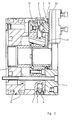
- Fig. 1 ein Spannfutter mit der erfindungsgemäßen Anordnung in stirnseitiger Ansicht,
- Fig. 2 den Gegenstand nach Fig. 2 im Axialschnitt,
- Fig. 3 eine der Fig. 1 entsprechende, schematische Darstellung einer anderen Ausführungsform,
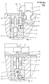
- Fig. 4 den Gegenstand der Erfindung in einer weiteren Ausführungsform im Axialschnitt,
- Fig. 5 einen Schnitt längs der Linie A-B durch den Gegenstand nach Fig. 4,
- Fig. 6 einen Schnitt durch eine geteilt ausgebildete Spannbacke mit am Kupplungsstück angebrachtem Spannkraft-Meßaufnehmer,
- Fig. 7 den Gegenstand nach Fig. 6 in einer anderen Ausführungsform,
- Fig. 8 eine schematische Schaltungsanordnung zur Fliehkraftkompensation.
- 1 is a chuck with the arrangement according to the invention in an end view,
- F i g. 2 the object according to FIG. 2 in axial section,
- 3 shows a schematic representation of another embodiment corresponding to FIG. 1,
- 4 the object of the invention in a further embodiment in axial section,
- 5 shows a section along the line AB through the object according to FIG. 4,
- 6 shows a section through a divided clamping jaw with a clamping force measuring sensor attached to the coupling piece,
- 7 shows the object according to FIG. 6 in another embodiment,
- Fig. 8 is a schematic circuit arrangement for centrifugal force compensation.
In der Zeichnung sind der Futterkörper des Spannfutters allgemein mit 1 und die darin radial verstellbar geführten Spannbacken mit 2 bezeichnet. Gemäß Fig. 1 besitzt ein solches Futter in der Regel drei Spannbacken 2, die zu ihrer radialen Verstellung beispielsweise über Keilhaken 1.2 mit einem Antriebsglied 1.3 in kraft- und formschlüssigem Eingriff stehen. Eine axiale Verstellung des Antriebsgliedes 1.3 bewirkt demzufolge eine radiale Verstellung der Spannbacken 2. Das Antriebsglied 1.3 kann in an sich bekannter und daher hier nicht näher zu beschreibender Weise durch einen Spannzylinder betätigt werden, dessen Spannkolben durch die hohle Drehmaschinenspindel hindurch über eine Zugstange oder ein Zugrohr mit dem Antriebsglied 1.3 verbunden sein kann.In the drawing, the chuck body of the chuck is generally designated 1 and the clamping jaws, which are guided in a radially adjustable manner therein, are designated by 2. 1, such a chuck generally has three
Unabhängig von der speziellen Ausbildung des Spannfutters ist im Kraftschluß zwischen dem Antriebsglied 1.3 und der Spannbacke 2 ein Spannkraft-Meßaufnehmer 3 angeordnet, der den Kraftfluß zwischen dem Antriebsglied 1.3 und der Spannbacke 2 erfaßt. Schließlich ist eine ebenfalls in der Zeichnung nicht näher dargestellte Signalübertragungseinrichtung vorgesehen, die aus einem Geberteil am Spannfutter, z. B. in Ringnuten 1.4 angeordneten Rotorspulen und einer gegenüber dem Spannfutter stationären Signalauswerteeinrichtung besteht.Regardless of the special design of the chuck, a
Der Futterkörper 1 ist mit einem Fliehkraftgeber 4 versehen, der von einem im Futterkörper 1 radial verstellbar geführten Fliehgewicht 7 und einem dessen Fliehkraft erfassenden Fliehkraft-Meßaufnehmer 6 gebildet ist. Dabei kann, wie in den Fig, 1 und 2 dargestellt, das Fliehgewicht 7 unmittelbar auf den Fliehkraft-Meßaufnehmer 6 einwirken. Im Ausführungsbeispiel nach Fig. 3 ist das Fliehgewicht 7 dagegen verstellbar an einem schwenkbar im Futterkörper 1 gelagerten Hebel 5 angeordnet, der zweiarmig ausgebildet ist. Der eine Arm 5.1 trägt das in Längsrichtung des Hebels 5 verstellbare Fliehgewicht 7, während der andere Arm 5.2 den Fliehkraft-Meßaufnehmer 6 beaufschlagt. In der Ausführung nach Fig. 3 verläuft die Schwenkachse 5.3 des Hebels 5 parallel zur Futterachse 8, wobei der Hebel 5 in im wesentlichen tangentialer Richtung im Futterkörper angeordnet ist. Im Ausführungsbeispiel nach den Fig. 4 und 5 verläuft dagegen die Schwenkachse 5.3 des Hebels 5 senkrecht zur Futterachse 8 und der Hebel 5 in zur Futterachse 8 im wesentlichen paralleler Richtung. Das längs des Hebelarms 5.1 verschiebbare Fliehgewicht 7 ermöglicht es, die durch die Fliehkraft auf den Fliehkraft-Meßaufnehmer ausgeübte Kraft in relativ weiten Grenzen zu variieren, wodurch eine Anpassung und Normierung des Ausgangssignals des Fliehkraft-Meßaufnehmers 6 insbesondere bezüglich der radialen Stellung, der Form und der Masse der Spannbakken möglich ist. Diese Einstellung kann bei der Ausführungsform der Fig. 3 beispielswdse auch von Hand durch auf dem Hebelarm 5.1 vorgesehene Markierungsrillen 9, bei der Ausführung nach Fig. 1 dagegen durch ein Potentiometer 20 erfolgen.The
In dem Ausführungsbeispiel der Fig. 4 und 5 ist zur Verstellung des Fliehgewichtes 7 ein parallel zur Futterachse verschiebbar geführter Verstellbolzen 10 vorgesehen, dessen freies Ende 10.1 zur Betätigung durch die Spannbacke 2 aus der Futterstirnfläche 1.1 vorsteht. Der Verstellbolzen 10 weist zwei Radialvorsprünge 11 auf, zwischen die das Fliehgewicht 7 des Hebels 5 unter Formschluß vorsteht. Das andere' Ende des Verstellbolzens 10 stützt sich über eine Druckfeder 12 am Futterkörper 1 innenseitig ab, wodurch der Verstellbolzen 10 mit seinem freien Ende 10.1 unter der Kraft der Druckfeder 12 einem an der Spannbacke 2 vorgesehenen Anschlag 13 anliegt. Die Anschlagfläche 13.1 des Anschlags 13 ist in Verstellrichtung der Spannbacke 2 als Steuerkulisse 13.1 ausgebildet, so daß bei radialer Verstellung der Spannbacke 2 der Verstellbolzen 10 und mit ihm das Fliehgewicht 7 axial verschoben wird. Wegen der linearen Abhängigkeit der Fliehkraft vom radialen Abstand kann die Steuerkulisse 13.1 in Verstellrichtung der Spannbacke 2 bezüglich der Futterstirnfläche 1.1 im wesentlichen keilförmig verlaufen. Bei geteilt ausgebildeten, aus Grundbacke 2.2 und Aufsatzbacke 2.3 bestehenden Spannbacke 2 ist der Anschlag 13 an der Aufsatzbacke 2.3 angeschlossen. Dadurch kann nicht nur die relative Lage der Aufsatzbacke 2.3 bei der Ermittlung der Fliehkraft berücksichtigt werden, vielmehr läßt sich die Aufsatzbacke 2.3 ohne weiteres auswechseln, wobei der jeweilige Anschlag 13 sowohl der Masse als auch der Form der Aufsatzbacke 2.3 Rechnung trägt. Dies geschieht dadurch, daß der Abstand der Steuerkulisse 13.1 an der Aufsatzbacke 2.3 von der Futterstirnfläche 1.1 abhängig von der Form und Masse der Aufsatzbacke 2.3 ist.In the exemplary embodiment in FIGS. 4 and 5, an
Es besteht jedoch auch die in der Zeichnung nicht näher dargestellte Möglichkeit, einen dem Verstellbolzen 10 entsprechenden Verstellstift vorzusehen, der einen linearen Weggeber beispielsweise in Form eines Potentiometers betätigt, dessen Ausgangssignal dann zur Normierung der Signalgröße des Fliehkraftgebers 4 zu der des Spannkraft-Meßaufnehmers 6 dient.However, there is also the possibility, not shown in the drawing, of providing an adjusting pin corresponding to the adjusting
Zur Ermittlung der tatsächlichen,am Werkstück angreifenden Betriebsspannkraft ist ein in der Fig. 8 nur schematisch dargestelltes Subtrahier- bzw. Addierglied 19 vorgesehen, das das Signal des in einer Brückenschaltung angeordneten Spannkraft-Meßaufnehmer 3 und das normierte, über ein Potentiometer 20 angepaßte Signal des Fliehkraft-Meßaufnehmers 6 bei Außenspannung des Futters voneinander subtrahiert bzw. bei Innenspannung zueinander addiert. Das Subtrahier- bzw. Addierglied 19 kann in bekannter Weise auch Teil eines entsprechend geschalteten Operationsverstärkers 18To determine the actual operating clamping force acting on the workpiece, a subtracting or adding
sein, der im Futterkörper 1 angeordnet sein kann. Ein dem Operationsverstärker 18 gegebenenfalls nachgeschalteter, in der Zeichnung jedoch nicht dargestellter Spannungs-Frequenz-Wandler ermöglicht eine besonders einfache und störsichere Übertragung des Signals vom Geberteil am Spannfutter zur stationären Signalauswerteeinrichtung.be that can be arranged in the
Der Spannkraft-Meßaufnehmer 3 ist in nicht näher dargestellter Weise als ein eine Längenveränderung erfassender Wegaufnehmer in Form eines Dehnungsmeßstreifens ausgebildet. Bei geteilt ausgebildeten Spannbak- ken 2, bei denen die Führungsbacke 2.1 und die Grundbacke 2.2 über ein beispielsweise als Verzahnungsbolzen ausgebildetes Kupplungsstück 14 auskuppelbar und formschlüssig miteinander verbunden sind, ist der Spannkraft-Meßaufnehmer 3 gemäß Fig. 6 und 7 am Kupplungsstück 14 angeordnet. Dabei kann der Spannkraft-Meßaufnehmer 3 gemäß Fig. 6 in einer Ausnehmung 15 an der Mantelfläche des Kupplungsstücks 14 angeordnet sein. Ebenso besteht jedoch die in Fig. 7 gezeigte Möglichkeit, den Spannkraft-Meßaufnehmer 3 in einer Ausnehmung 16 des das Kupplungsstück 14 in axialer Richtung verstellenden Stellrings 17 anzuordnen, dem das Kupplungsstück 14 stirnseitig anliegt.The
Das vom Geberteil zur stationären Signa2auswerteeiri- richtung übertragene, die tatsächlich am Werkstück auftretende Betriebsspannkraft wiedergebende Signal kann schließlich in nicht näher dargestellter Weise zur Verwendung bei der Steuerung der das Spannfutter antreibenden Drehmaschine zur Verfügung stehen. Derart registrierte Änderungen der Spannkraft, insbesondere deren Absinken unter einen vorgegebenen Wert, können dazu verwendet werden, auf einen erforderlichen Werkzeugwechsel hinzuweisen oder auch die Maschine stillzusetzen. Ebenso kann auf die Höhe der vom Spannzylinder aufgebrachten Spannkraft korrigierend Einfluß genommen werden.The signal which is transmitted from the transmitter part to the stationary signal evaluation device and which reflects the operating clamping force actually occurring on the workpiece can finally be available in a manner not shown for use in controlling the lathe driving the chuck. Changes in the clamping force registered in this way, in particular their lowering below a predetermined value, can be used to indicate a necessary tool change or to shut down the machine. The height of the clamping force applied by the clamping cylinder can also be corrected.
Claims (19)
Applications Claiming Priority (2)
| Application Number | Priority Date | Filing Date | Title |
|---|---|---|---|
| DE19843439402 DE3439402A1 (en) | 1984-10-27 | 1984-10-27 | POWERED CHUCK |
| DE3439402 | 1984-10-27 |
Publications (2)
| Publication Number | Publication Date |
|---|---|
| EP0180731A1 true EP0180731A1 (en) | 1986-05-14 |
| EP0180731B1 EP0180731B1 (en) | 1988-11-17 |
Family
ID=6248912
Family Applications (1)
| Application Number | Title | Priority Date | Filing Date |
|---|---|---|---|
| EP19850110789 Expired EP0180731B1 (en) | 1984-10-27 | 1985-08-28 | Power-operated chuck |
Country Status (2)
| Country | Link |
|---|---|
| EP (1) | EP0180731B1 (en) |
| DE (1) | DE3439402A1 (en) |
Cited By (5)
| Publication number | Priority date | Publication date | Assignee | Title |
|---|---|---|---|---|
| EP0919313A2 (en) * | 1997-11-25 | 1999-06-02 | Röhm GmbH | Clamping device |
| EP1291102A1 (en) * | 2001-09-05 | 2003-03-12 | Yamazaki Mazak Kabushiki Kaisha | Control unit of machine tool |
| US20090072499A1 (en) * | 2007-09-17 | 2009-03-19 | Rohm Georg | System for centrifugal-force compensation in a hydraulic machining-chuck actuator |
| CN110907080A (en) * | 2019-12-02 | 2020-03-24 | 佛山市宏石激光技术有限公司 | Method for measuring clamping force of clamping jaw of pneumatic chuck |
| CN112262016A (en) * | 2019-03-26 | 2021-01-22 | 罗姆股份有限公司 | Method for determining a clamping force |
Families Citing this family (4)
| Publication number | Priority date | Publication date | Assignee | Title |
|---|---|---|---|---|
| DE3937466A1 (en) * | 1989-11-10 | 1991-05-16 | Heiko Dipl Ing Noske | METHOD AND DEVICE FOR MONITORING THE CLAMPING FORCE IN MACHINE TOOLS |
| DE4040309A1 (en) * | 1990-12-17 | 1992-07-02 | Spur Guenter | DEVICE FOR MONITORING CLAMPING FORCES IN LATHE CHUCK |
| DE4220136C1 (en) * | 1992-06-15 | 1993-09-30 | Spur Guenter Prof Dr Ing Dr H | Clamping system for machine tools |
| CN104374274A (en) * | 2014-11-13 | 2015-02-25 | 上海众力投资发展有限公司 | Gauge for inspecting external diameters of parts |
Citations (3)
| Publication number | Priority date | Publication date | Assignee | Title |
|---|---|---|---|---|
| DE2236651A1 (en) * | 1972-07-26 | 1974-02-07 | Hofmann & Co Kg W | JAWS |
| EP0079131A1 (en) * | 1981-10-29 | 1983-05-18 | Pratt Burnerd International Limited | Workholding devices |
| EP0108857A2 (en) * | 1982-11-10 | 1984-05-23 | Günter Horst Röhm | Power-actuated clamping chuck |
Family Cites Families (1)
| Publication number | Priority date | Publication date | Assignee | Title |
|---|---|---|---|---|
| US4254676A (en) * | 1977-10-29 | 1981-03-10 | Pratt Burnerd International Limited | Workholding |
-
1984
- 1984-10-27 DE DE19843439402 patent/DE3439402A1/en active Granted
-
1985
- 1985-08-28 EP EP19850110789 patent/EP0180731B1/en not_active Expired
Patent Citations (3)
| Publication number | Priority date | Publication date | Assignee | Title |
|---|---|---|---|---|
| DE2236651A1 (en) * | 1972-07-26 | 1974-02-07 | Hofmann & Co Kg W | JAWS |
| EP0079131A1 (en) * | 1981-10-29 | 1983-05-18 | Pratt Burnerd International Limited | Workholding devices |
| EP0108857A2 (en) * | 1982-11-10 | 1984-05-23 | Günter Horst Röhm | Power-actuated clamping chuck |
Cited By (10)
| Publication number | Priority date | Publication date | Assignee | Title |
|---|---|---|---|---|
| EP0919313A2 (en) * | 1997-11-25 | 1999-06-02 | Röhm GmbH | Clamping device |
| EP0919313A3 (en) * | 1997-11-25 | 2001-04-25 | Röhm GmbH | Clamping device |
| US6341553B1 (en) | 1997-11-25 | 2002-01-29 | Rohm Gmbh | Chuck actuator with pressure sensor |
| EP1291102A1 (en) * | 2001-09-05 | 2003-03-12 | Yamazaki Mazak Kabushiki Kaisha | Control unit of machine tool |
| US6705186B2 (en) | 2001-09-05 | 2004-03-16 | Yamazaki Mazak Kabushiki Kaisha | Control unit of machine tool |
| US20090072499A1 (en) * | 2007-09-17 | 2009-03-19 | Rohm Georg | System for centrifugal-force compensation in a hydraulic machining-chuck actuator |
| CN112262016A (en) * | 2019-03-26 | 2021-01-22 | 罗姆股份有限公司 | Method for determining a clamping force |
| CN112262016B (en) * | 2019-03-26 | 2022-06-28 | 罗姆股份有限公司 | Method for determining a clamping force |
| CN110907080A (en) * | 2019-12-02 | 2020-03-24 | 佛山市宏石激光技术有限公司 | Method for measuring clamping force of clamping jaw of pneumatic chuck |
| CN110907080B (en) * | 2019-12-02 | 2020-07-24 | 佛山市宏石激光技术有限公司 | Method for measuring clamping force of clamping jaw of pneumatic chuck |
Also Published As
| Publication number | Publication date |
|---|---|
| DE3439402A1 (en) | 1986-04-30 |
| DE3439402C2 (en) | 1993-05-06 |
| EP0180731B1 (en) | 1988-11-17 |
Similar Documents
| Publication | Publication Date | Title |
|---|---|---|
| EP0108857B1 (en) | Power-actuated clamping chuck | |
| EP2427722B1 (en) | Method and device for measuring a surface profile | |
| DE2846337A1 (en) | WORKPIECE HOLDER | |
| DE3419944C1 (en) | Device for guiding a wire or band-shaped cutting electrode on a machine tool | |
| EP2493647A1 (en) | Precision turning tool | |
| EP0180731A1 (en) | Power-operated chuck | |
| DE3246691C2 (en) | ||
| DE3212761C2 (en) | ||
| EP0303564B1 (en) | Measuring device for the pulling force between a tool and the spindle nose of a machine tool | |
| DE3238336C2 (en) | ||
| WO2005010457A2 (en) | Roughness measuring device with measurement standard | |
| DE19852182C1 (en) | Cable pull distance sensor for full bridge bending measurement and wire strain gauge measurement applies the displacement of a traction rope over a cable drum to convert into spindle axial displacement. | |
| DE3920310A1 (en) | MATERIAL TENSION METER AND MATERIAL TENSION REGULATOR | |
| DE19753563B4 (en) | Cutting device for flat material webs | |
| DE4208701C2 (en) | Process for clamping a workpiece in a CNC lathe | |
| CH649012A5 (en) | MEASURING DEVICE FOR DETECTING THE GAP OF A WORKING ROLLER PAIR. | |
| DE2723104C2 (en) | Device for measuring the angle of inclination of a workpiece surface | |
| DE3930306C2 (en) | ||
| DE3937466C2 (en) | ||
| DE19606145B4 (en) | Device for expanding a honing tool | |
| DE3500050C2 (en) | Measuring head for cylindrical grinding machines | |
| DE4432582C2 (en) | Device for measuring radial force on centering points of machine tools | |
| DE2058847C3 (en) | Device for measuring the main cutting force on a lathe | |
| DE2334932C3 (en) | Device for the longitudinal alignment of a workpiece to be ground in relation to the grinding wheel of a cylindrical grinding machine | |
| DE1814984C3 (en) | Measuring device for controlling the machining process in grinding machines |
Legal Events
| Date | Code | Title | Description |
|---|---|---|---|
| PUAI | Public reference made under article 153(3) epc to a published international application that has entered the european phase |
Free format text: ORIGINAL CODE: 0009012 |
|
| 17P | Request for examination filed |
Effective date: 19860307 |
|
| AK | Designated contracting states |
Kind code of ref document: A1 Designated state(s): CH FR GB IT LI SE |
|
| 17Q | First examination report despatched |
Effective date: 19870727 |
|
| GRAA | (expected) grant |
Free format text: ORIGINAL CODE: 0009210 |
|
| AK | Designated contracting states |
Kind code of ref document: B1 Designated state(s): CH FR GB IT LI SE |
|
| ITF | It: translation for a ep patent filed |
Owner name: STUDIO JAUMANN |
|
| ET | Fr: translation filed | ||
| GBT | Gb: translation of ep patent filed (gb section 77(6)(a)/1977) | ||
| PLBE | No opposition filed within time limit |
Free format text: ORIGINAL CODE: 0009261 |
|
| STAA | Information on the status of an ep patent application or granted ep patent |
Free format text: STATUS: NO OPPOSITION FILED WITHIN TIME LIMIT |
|
| 26N | No opposition filed | ||
| ITTA | It: last paid annual fee | ||
| EAL | Se: european patent in force in sweden |
Ref document number: 85110789.6 |
|
| PGFP | Annual fee paid to national office [announced via postgrant information from national office to epo] |
Ref country code: SE Payment date: 19950612 Year of fee payment: 11 |
|
| PGFP | Annual fee paid to national office [announced via postgrant information from national office to epo] |
Ref country code: CH Payment date: 19950623 Year of fee payment: 11 |
|
| PG25 | Lapsed in a contracting state [announced via postgrant information from national office to epo] |
Ref country code: SE Effective date: 19960829 |
|
| PG25 | Lapsed in a contracting state [announced via postgrant information from national office to epo] |
Ref country code: LI Effective date: 19960831 Ref country code: CH Effective date: 19960831 |
|
| REG | Reference to a national code |
Ref country code: CH Ref legal event code: PL |
|
| EUG | Se: european patent has lapsed |
Ref document number: 85110789.6 |
|
| PGFP | Annual fee paid to national office [announced via postgrant information from national office to epo] |
Ref country code: FR Payment date: 20010712 Year of fee payment: 17 |
|
| PGFP | Annual fee paid to national office [announced via postgrant information from national office to epo] |
Ref country code: GB Payment date: 20010803 Year of fee payment: 17 |
|
| REG | Reference to a national code |
Ref country code: GB Ref legal event code: IF02 |
|
| PG25 | Lapsed in a contracting state [announced via postgrant information from national office to epo] |
Ref country code: GB Free format text: LAPSE BECAUSE OF NON-PAYMENT OF DUE FEES Effective date: 20020828 |
|
| GBPC | Gb: european patent ceased through non-payment of renewal fee |
Effective date: 20020828 |
|
| PG25 | Lapsed in a contracting state [announced via postgrant information from national office to epo] |
Ref country code: FR Free format text: LAPSE BECAUSE OF NON-PAYMENT OF DUE FEES Effective date: 20030430 |
|
| REG | Reference to a national code |
Ref country code: FR Ref legal event code: ST |