EP0180096B1 - Wheel slip control system - Google Patents
Wheel slip control system Download PDFInfo
- Publication number
- EP0180096B1 EP0180096B1 EP85113148A EP85113148A EP0180096B1 EP 0180096 B1 EP0180096 B1 EP 0180096B1 EP 85113148 A EP85113148 A EP 85113148A EP 85113148 A EP85113148 A EP 85113148A EP 0180096 B1 EP0180096 B1 EP 0180096B1
- Authority
- EP
- European Patent Office
- Prior art keywords
- pressure
- slip
- control
- adjustment signal
- brake
- Prior art date
- Legal status (The legal status is an assumption and is not a legal conclusion. Google has not performed a legal analysis and makes no representation as to the accuracy of the status listed.)
- Expired - Lifetime
Links
Images


Classifications
-
- B—PERFORMING OPERATIONS; TRANSPORTING
- B60—VEHICLES IN GENERAL
- B60T—VEHICLE BRAKE CONTROL SYSTEMS OR PARTS THEREOF; BRAKE CONTROL SYSTEMS OR PARTS THEREOF, IN GENERAL; ARRANGEMENT OF BRAKING ELEMENTS ON VEHICLES IN GENERAL; PORTABLE DEVICES FOR PREVENTING UNWANTED MOVEMENT OF VEHICLES; VEHICLE MODIFICATIONS TO FACILITATE COOLING OF BRAKES
- B60T8/00—Arrangements for adjusting wheel-braking force to meet varying vehicular or ground-surface conditions, e.g. limiting or varying distribution of braking force
- B60T8/17—Using electrical or electronic regulation means to control braking
- B60T8/176—Brake regulation specially adapted to prevent excessive wheel slip during vehicle deceleration, e.g. ABS
- B60T8/1761—Brake regulation specially adapted to prevent excessive wheel slip during vehicle deceleration, e.g. ABS responsive to wheel or brake dynamics, e.g. wheel slip, wheel acceleration or rate of change of brake fluid pressure
- B60T8/17616—Microprocessor-based systems
-
- B—PERFORMING OPERATIONS; TRANSPORTING
- B60—VEHICLES IN GENERAL
- B60T—VEHICLE BRAKE CONTROL SYSTEMS OR PARTS THEREOF; BRAKE CONTROL SYSTEMS OR PARTS THEREOF, IN GENERAL; ARRANGEMENT OF BRAKING ELEMENTS ON VEHICLES IN GENERAL; PORTABLE DEVICES FOR PREVENTING UNWANTED MOVEMENT OF VEHICLES; VEHICLE MODIFICATIONS TO FACILITATE COOLING OF BRAKES
- B60T8/00—Arrangements for adjusting wheel-braking force to meet varying vehicular or ground-surface conditions, e.g. limiting or varying distribution of braking force
- B60T8/17—Using electrical or electronic regulation means to control braking
- B60T8/175—Brake regulation specially adapted to prevent excessive wheel spin during vehicle acceleration, e.g. for traction control
-
- B—PERFORMING OPERATIONS; TRANSPORTING
- B60—VEHICLES IN GENERAL
- B60T—VEHICLE BRAKE CONTROL SYSTEMS OR PARTS THEREOF; BRAKE CONTROL SYSTEMS OR PARTS THEREOF, IN GENERAL; ARRANGEMENT OF BRAKING ELEMENTS ON VEHICLES IN GENERAL; PORTABLE DEVICES FOR PREVENTING UNWANTED MOVEMENT OF VEHICLES; VEHICLE MODIFICATIONS TO FACILITATE COOLING OF BRAKES
- B60T8/00—Arrangements for adjusting wheel-braking force to meet varying vehicular or ground-surface conditions, e.g. limiting or varying distribution of braking force
- B60T8/32—Arrangements for adjusting wheel-braking force to meet varying vehicular or ground-surface conditions, e.g. limiting or varying distribution of braking force responsive to a speed condition, e.g. acceleration or deceleration
- B60T8/34—Arrangements for adjusting wheel-braking force to meet varying vehicular or ground-surface conditions, e.g. limiting or varying distribution of braking force responsive to a speed condition, e.g. acceleration or deceleration having a fluid pressure regulator responsive to a speed condition
- B60T8/48—Arrangements for adjusting wheel-braking force to meet varying vehicular or ground-surface conditions, e.g. limiting or varying distribution of braking force responsive to a speed condition, e.g. acceleration or deceleration having a fluid pressure regulator responsive to a speed condition connecting the brake actuator to an alternative or additional source of fluid pressure, e.g. traction control systems
Definitions
- the present invention relates to a wheel slip control system for a vehicle operable so as to control the rotation of the driven wheels to control the power of the internal combustion engine as well as to control the braking system for the driven wheels during an acceleration slip.
- Document DE-A-31 27 302 discloses a system for controlling the propulsive drive applied to motor vehicle wheels, particularly having hydraulically operated disc brakes, in the sense of preventing undesired spinning of the driven vehicle wheels in order to obtain a desired vehicle attitude in critical driving situations, especially under extreme road conditions.
- a comparator is provided which is triggered by at least one presettable or permanently preset threshold value corresponding to the speed of the vehicle, and which generates an output signal causing the drive torque to be reduced as soon as the threshold value is exceeded and a signal is present, which indicates that the individual wheel brake is being activated and/or that one of the driven wheels is tending to spin.
- the control system comprises a first control loop which reacts to the state of motion of at least the driven vehicle wheels and which, when one of these wheels is tending to spin, activates its wheel brake, and comprises a second control loop applying a torque-reducing control action to the drive unit of the vehicle when values preferably being determined from the wheel rotation speeds of the undriven vehicle wheels and representing the speed and the acceleration of the vehicle exceed the threshold value.
- the threshold value of the speed of the vehicle which value governs the control process, is preferably regulated in accordance with the transverse acceleration which acts on the vehicle whenever it follows a curved path, thus performing a control of the vehicle attitude depending on the detected vehicle speed and being additionally adapted to the vehicle cornering state.
- the control of internal combustion engine power and that of the rotation of the driven wheels are carried out by adjusting, e.g., the ignition timing and the fuel injection amount when the degree of a driven wheel slip is found to exceed a predetermined value.
- the conventional wheel slip control systems aim at the prevention of slip during acceleration by reducing the fuel injection amount or setting a time lag against a change in the ignition timing so as to control the output of the internal combustion engine.
- the control capacity being limited, taking preventive measures against abnormal vibration or fire due to abrupt changes in the operating conditions of the engine.
- a pressure source will be required for the purpose of increasing braking pressure supplied to a braking cylinder equipped with the driven wheels of the control system for vehicles. Therefore, an oil pump must be added to conventional vehicles in order to activate the brake for a throttle control (A small-type pump is acceptable).
- the objective of the present invention is to solve the above-mentioned problems and offer a wheel slip control system capable of carrying out a fine control without any decrease in drivability and safety of vehicles as well as any delay in control when the slip of the driven wheels occurs during an acceleration operation.
- Another objective of the present invention is to offer a wheel slip control system wherein the braking force of wheels including driven wheels is controlled by a braking means, so-called anti-skid control system in braking and traction control in acclerating, and other pressure sources mounted on vehicles and the output of an internal combustion engine is controlled by a second throttle valve which controls the intake air amount in a longer period, thus the driven wheels can be operated with the most suitable driving force by controlling the driving force of the driven wheels to prevent the occurrence of an excessive slip like locking, accompanying skidding ,etc.
- the other objective of the present invention is to offer a wheel slip control system wherein the traction control system is easily added to vehicles equipped with the anti-skid control system and other pressure sources, as the device and constitution of the anti-skid control system are simplified by utilizing a hydraulic system, which leads to the capability of conducting a fine control of the braking force and minimizing the necessary devices used for traction control only.
- a wheel slip control system used for a vehicle comprising:
- a part of a so-called anti-skid brake control system which controls the brake of the wheels by changing the hydraulic pressure of the hydraulic pressure system in accordance with the first pressure source operated by the driver when the slip condition of the vehicle is detected during a braking operation of the vehicle, is used in common.
- the second pressure source mounted on the vehicle separately from the first one as the pressure source of the hydraulic pressure system for said brake control means the position of said second throttle valve as well as the pressure of the hydraulic pressure system are controlled.
- the wheel slip control system in order to perform an accurate traction control of the driven wheels provides three adjustment signals upon which the control process is based.
- the first adjustment signal is related to the brake slip detected and judged by a brake slip detecting means and is used to control the driven wheel speed concerning a braking.
- the second and third adjustment signals are generated by the second control means on the basis of the detected and scaled acceleration slip signals for engine output control, respectively.
- the second electronic control means processes the second and third adjustment signal and controls the hydraulic control means in accordance with the second adjustment signal to provide an immediate fine traction control of the driven vehicle wheels during acceleration of the vehicle, thereby activating the individual wheel brakes if necessary.
- the third adjustment signal is used to start a control action reducing the drive torque of the internal combustion engine.
- the second electronic control means is connected via a control line to the drive means of a throttle valve for adjusting the position of the throttle valve in accordance with the required reduction of drive torque and in consideration of the previously carried out control of the individual wheel brakes by means of the hydraulic control means.
- the first pressure source M1 characterizes the pressure obtained from a brake pedal operated directly or indirectly by the driver and the artificial pressure amplified by machinery, like powerbrake, may be acceptable.
- the second pressure source M2 indicates any pressure sources mounted on vehicles, for example, the pressure sources for anti-skid or power steering, etc.
- the pressure source selection means M3 may have the constitution which gives priority to the source of a higher pressure.
- the combination of check valves and the use of a shuttle valve may be adopted.
- the constitution which selects the suitable pressure source compulsorily in accordance with the state of slip control of the vehicle may be allowed.
- the brake slip detection means M6 detects the slip condition of the driven wheels M4 during a braking operation, e.g. one judges the slip when the difference between the vehicle speed and the driven wheel speed exceeds a predetermined value, or the other detects the slip when the detected acceleration of the driven wheels lowers to a predetermined negative value.
- an acceleration slip detection means M7 detects the slip (lock) of the driven wheels during an accelerating operation, e.g., one decides the slip when the difference between the vehicle speed and the driven wheel speed exceeds a predetermined value or the other detects the slip in accordance with the difference of speed (number of rotations) between the driven wheels and the non-driven wheels , further, the other judges the slip when the acceleration of the rotations of the driven wheels is above a predetermined value.
- said brake slip detection means M6 and said acceleration slip detection means M7 to have the same constitution if only the parameter is changed. As the brake slip and the acceleration slip do not occur concurrently, there are no problems for using the system in common. Thus, that has such a remarkable merit as being capable of simplifying the system and the constitution.
- An electronic control means M11 inputs signals from said acceleration slip detection means M7 and said brake slip detection means M6 and controls the hydraulic pressure of said slip control means M5 and the position of said second throttle valve M10. It is constituted so as to control the position of said second throttle valve M10 by an actuator, etc. as well as to decrease, hold or increase the hydraulic pressure by a 3-position 3-port valve, etc. Such a constitution as controlling the position of said 3-position 3-port valve and the operation amount of said actuator by a microcomputer in addition to said brake slip detection means M6 and said acceleration slip detection means M7 may also be realized by discrete circuit constructions for every means.
- the suitable brake force is given to the wheels by pressure of the second pressure source and the output of the internal combustion engine which operates the driven wheels is controlled by adjusting the intake air amount with said second throttle valve. Therefore, a quick response of the traction control can be secured by the former and the unnecessary power from the internal combustion engine can be reduced by the latter when the traction control is conducted. In other words, the economic efficiency and the durability are satisfied.
- Fig. 2 showing generally a first embodiment of the inventive wheel slip control system
- numeral 1 shows an internal combustion engine
- 2 shows a fuel injection valve
- 3 shows an intake air path
- the intake air path 3 is provided with a first throttle valve 5 which interlocks to an accelerator pedal 4 and a second throttle valve 7 which is driven by a DC motor 6 so as to adjust the intake air amount.
- said second throttle valve 7 is fully opened. It is controlled from the full open to the full close so as to control the power of the internal combustion engine for the traction control only.
- the slip control is executed when the valve is half-opened.
- the arrangement includes a brake pedal 11, a brake master cylinder 12 serving as the first pressure source for providing a brake hydraulic pressure in response to a displacement of the brake pedal 11, a sub-master cylinder 13 serving as the second pressure source for providing a brake hydraulic pressure derived from the power steering hydraulic system upon detection of an acceleration slip as described later, non-driven right and left wheels 14 and 15 of the vehicle, driven right and left wheels 16 and 17, wheel cylinders 18 ⁇ 21 provided for the wheels 14 ⁇ 17, a hydraulic system 23 used for anti-skid control, a power steering hydraulic system 24 for both anti-skid and traction controls, a non-driven wheel speed sensor 25 generating a pulse signal at frequencies in proportion to the rotational speed of the non-driven wheels 14 and 15, a driven-wheel speed sensor 26 generating a pulse signal at frequencies in proportion to the rotational speed of the driven wheels 16 and 17, and an electronic control circuit 30 implementing anti-skid control and traction control as well by controlling the hydraulic system 23 and 24.
- the brake master cylinder 12 is of a tandem master cylinder assembly, supplying a brake oil pressure to the wheel cylinders 18 and 19 on the non-driven wheels 14 and 15 in one hydraulic system, and to the wheel cylinders 20 and 21 of the driven wheels 16 and 17 in another.
- the brake oil pressure produced by the sub-master cylinder 13 is used for the braking of driven wheels 16 and 17, and as to which of this brake hydraulic pressure or that produced by the brake master cylinder 2 is supplied by way of the anti-skid hydraulic system 23 to the wheel cylinders 20 and 21 is determined by a change valve 32 serving as the pressure source selection means.
- the change valve 32 has the structure of a shuttle valve, supplying the higher of the above two hydraulic pressures to the anti-skid hydraulic system 23.
- the anti-skid hydraullic system 23 has major hydraulic paths for supplying the pressure from the change valve 32 to the wheel cylinders 20 and 21 via a 3-position valve 34, and operates to increase the pressure by means of an oil pump 36 and hold or decrease (release the pressure to a reservoir 38) depending on the position of the 3-position valve 34.
- the system 23 further includes check valves 39, 40 and 41, the hydraulic path via the valve 41 being used to decrease the pressure (decrease the braking force) by the operation of the brake pedal when the 3-position valve 34 is set at "hold” position.
- the 3-position valve 34 is operated by the electronic circuit 30, and positions a , b and c in Fig. 2 correspond to "increase pressure", “hold pressure” and "decrease pressure", respectively.
- the position of the oil-pressure switch 56 is informed to the electronic
- the electronic control circuit 30 includes the anti-skid control circuit (ES), but this section unrelated directly to the present invention will be disregarded in the following description.
- the traction control circuit 30' operates to receive the pulse signal from the non-driven wheel speed sensor 25 on an F/V converter 70, differentiate its voltage output Vfr by a differentiator 71 to obtain the acceleration of the vehicle, and compare the differentiated output with a zero level by a comparator 72 to obtain a signal Vfc indicative of as to whether the vehicle is in acceleration or deceleration.
- the signal Vfc is sent to the anti-skid control circuit ESC, which is activated when Vfc is at a low level.
- a threshold-1 generator 73a and an adder 74a in unison produce the first slip threshold level Vfbh
- a threshold-2 generator 73b and an adder 74b in unison produce the second slip threshold level Vfbl
- a threshold-3 generator 73c and an adder 74c in unison produce the third slip threshold level Vfsh
- a threshold-4 generator 73d and an adder 74d in unison produce the fourth slip threshold level Vfsl.
- the first and second slip threshold signals, Vfbh and Vfbl are employed as threshold level for controlling the braking force by means of said anti-skid hydraulic system 23 and the third and forth slip threshold signals, Vfsh and Vfsl, as threshold level for controlling intake air amount of said internal combustion engine 1 by means of said second throttle valve 7.
- the first two signals Vcbh and Vcbl indicated comparison of the driven wheel speed Vrr with the first threshold level Vfbh and second threshold level Vfbl provided based on the non-driven wheel speed Vfr as shown in Fig. 4.
- the fourth slip threshold signal Vfsl gives a timing for the preparation of traction control
- the first slip threshold signal Vfbh gives a timing for carrying out traction control by increasing the brake oil pressure.
- the third slip threshold signal Vcsh generated by comparing the third slip threshold level Vfsh with the driving wheel speed indicates the timing when said throttle valve 7 is driven toward closing position by operating said motor 6 in normal direction.
- the fourth slip threshold signal Vcsl generated by comparing the fourth slip threshold level Vfsl with the driven wheel speed indicates the timing when said throttle valve 7 is driven toward opening position by operating said motor 6 in the opposite direction.
- the traction control circuit 30' further operates to differentiate the signal Vrr representing the driven wheel speed to obtain a signal Vrg representing the accelerating of the driven wheels 16 and 17.
- the signal Vrg is compared with an output signal G1 from a threshold-5 generator 84 and an output signal G2 from a threshold-6 generator 85 by comparators 87 and 88, respectively, and the first slip control signal Vrgh and second slip control signal Vrgl are obtained.
- a lower slip threshold signal Vfbl goes high, causing a delay circuit 89 formed of a monostable multivibrator to produce a high output, and a 2-input AND gate 90a produces a high output Vrt as shown in Fig. 4.
- This signal goes through a 2-input OR gate 91 and an amplifier 92 to activate the oil pump 36 in the anti-skid hydraulic system 23 and, at the same time, goes through an amplifier 90b to switch the M/C up-pressure valve 57 to position f so that an oil path for conducting the power steering oil pressure to the sub-master cylinder 13 is formed.
- a 3-input AND gate 90c provides an output Vrs, and when the Vrs becomes high, it goes through an amplifier 93 to switch the PS up-pressure valve 58 to position i and the steering gear box 55 is throttled and the power steering hydraulic pressure is conducted to the sub-master cylinder 13.
- the purpose of entering then output of the oil pressure switch 56 to the 3-input AND gate 90c is to switch the PS up-pressure valve 58 so as to prevent an unnecessary increase in the oil pressure which is raised automatically when the steering wheel is turned during traction control operation.
- the arrangement also works to supply the oil pressure to the power steering system in precedence over the traction control system.
- the 3-position valve 34 in the anti-skid hydraulic system 23 has its three positions a , b and c controlled in response to the state of a transistor Tr1 driven by the output of an amplifier 95 and the state of a transistor Tr2 provided with a current limiting resistor R and driven by the output of another amplifier 96.
- the valve position is determined by the combination of the transistor outputs as follows. Tr1 Tr2 Valve Position Brake Oil Pressure OFF OFF a Increase OFF ON b Hold ON ON c Decrease
- the amplifier 96 for driving the transistor Tr2 receives the output Vru of a 3-point AND gate 97, which signal Vru is determined by the logical sum of the output of a 2-point NAND gate 98 receiving the supper slip threshold signal Vcbh and first slip control signal Vrgh, the signal Vrt, and the control signal from the anti-skid control circuit (ESC), as shown in Fig. 4.
- the amplifier 95 for driving the transistor Tr1 receives the output signal Vrd of a 2-input OR gate 99, which signal Vrd is determined by the logical sum of the output of a 2-input AND gate 101 receiving the lower slip threshold signal Vcb1 inverted by an inverter 100 and the second slip control signal Vrgl, and the input signal from the ESC.
- said second throttle valve 7 is controlled as follows by the third and fourth slip threshold signals Vcsh and Vcsl respectively.
- the third and fourth slip threshold signals are in low level, the output of a 2-input NOR gate 105 Vcsc becomes high level and a normal-reverse amplifier 107 feeds the current so as to operate said motor 6 in the opposite direction until said throttle valve 7 is fully opened. Consequently, said second throttle valve 7 is fully opened and the intake air amount is controlled by said first throttle valve 5 interlocked to said accelerator pedal 4.
- the fourth slip threshold signal Vcsl is high in level, the output of said 2-input NOR gate 105 Vcsc becomes low level, thus, said normal-reverse amplifier 107 does not supply the power to said motor 6.
- the necessary braking force for traction control is minimized and the reduction of the hydraulic system in size and weight is made possible. Also, the fuel consumption is improved because no extra fuel is supplied to the internal combustion engine 1 when the braking force is generated, and at the same time, the exothermic of brake system which supplies the braking force can be prevented.
- This traction control is easily implemented without the need of a specialized hydraulic system and devices, but by utilization of the hydraulic system used for the anti-skid operation, the 3-position valve 34 used therein, and the power steering hydraulic system for obtaining the braking oil pressure independently of the driver's action. On this account, traction control can be established merely through a little modification for the piping and replacement of the electronic control circuit 30 for a vehicle which already installs the anti-skid control and power steering systems. It should be noted in Fig. 3 that the remaining one input to the 2-input OR gates 91 and 99 and the 3-point AND gate 97 respectively and to allow the anti-skid control circuit (ESC) to control the 3-position valve 34 and oil pump 36. Since anti-skid control and traction control do not take place concurrently, these systems can be shared by separate purposes through a simple logical sum process.
- the second embodiment is intended to control the hydraulic systems and associated devices similar to those of the first embodiment shown in Fig. 2 through an electronic control circuit 30 which is in this case constituted mainly by a microcomputer as shown in Fig. 5.
- the control is executed according to the flowchart shown in Figs. 6 (A) and (B).
- the arrangement of Fig. 5 includes a central processing unit (CPU) 110 which is programmed to receive the sensor signals from the driven wheel speed sensor 26, non-driven wheel speed sensor 25 and oil pressure switch 56, and perform various calculations in response to these input signals.
- CPU central processing unit
- ROM read-only memory
- RAM random access memory
- input interface circuit 114 including waveform shaping circuits and a multiplexer for supplying sensor input signals selectively to the CPU 110
- an output circuit 116 for driving the oil pump 36, M/C up-pressure valve 57 and PS up-pressure valve 58 and also driving the 3-position valve 34 through transistors Tr1 and Tr2, and a bus line 118 for providing data communication between the CPU 110, ROM 112, RAM 113, and input/output interface circuits 114 and 116, and a power supply circuit 120 for all of the above circuit components.
- the 3-position valve 34 and the motor 6 are constituted so as to be driven by the output circuit interface circuit 116 via transistors Tr1 and Tr2, a power restricting resistor R and PWM drive circuit 125 which conducts pulse width modulation respectively.
- Step 200 Read input data on the input interface circuit 114 of the driven wheel speed vr from the driven wheel sensor 26, the non-driven wheel speed vf from the non-driven wheel sensor 25, and the switch state from the oil pressure switch 56.
- Step 220 Perform differentiation process for the driven wheel speed vr to obtain acceleration ⁇ of the driven wheels.
- Step 230 Test whether the driven wheel acceleration is above zero (acceleration).
- Step 240 Calculate the slip thereshold levels vs1, vs2, vs3 and vs4 from the non-driven wheel speed vf using predetermined constants K1, K2, K3, K4 (K2>K3>K4>K1), g1, g2, g3 and g4 as follows.
- vs1 K1 x vf + g1
- vs2 K2 x vf + g2
- Step 242 Decide whether the driven wheel speed is above the third slip threshold level vs3 or not.
- Step 244 Decide whether the driven wheel speed is equal or below the fourth slip thereshold level vs4 or not.
- Slip 246 Output the normal signal via the output interface circuit 116 so as to control the position of the second throttle valve 7 toward the full close position by operating the motor 6 with the PWM drive circuit 125 in normal rotation.
- Step 247 Output the reverse signal via the output interface circuit 116 so as to control the position of the throttle valve 7 toward the full open position by operating the motor 6 with the PWM drive circuit 125 in opposite rotation.
- Step 248 Reset the output of the normal and the reverse signals mentioned above.
- Step 250 Test whether the driven wheel speed vr is higher than the first thereshold level vs1.
- Step 260 Set a predetermined value to the counter C in the CPU.
- Step 270 Reset the counter C to zero.
- Step 280 Decrement the counter C by one.
- Step 290 Test whether the content of counter C is above zero.
- the counter C used in the steps 260-290 is actually a programmed operation substituting the delay circuit 89 in the first embodiment, and its purpose is to continue traction control for a preset time length when the speed vr of driven wheels 16 and 17 has fallen below the first threshold level vs1 after traction control had been commenced.
- Step 293 Test whether the oil pressure switch 56 is OFF. If the switch is OFF, indicating the steering operation being inert and the power steering hydraulic pressure not being increased, the sequence proceeds to step 350.
- Step 296 If the oil pressure switch 56 is found ON in step 293, indicating the steering operation, the PS up-pressure valve 58 is reset to position h .
- Step 300 Set or hold the M/C up-pressure valve 57 in the power steering hydraulic system 24 to position f, and activate the oil pump 36.
- Step 303 Test whether the oil switch 56 is OFF.
- Step 306 If the oil pressure switch 56 is OFF, switch the PS up-pressure valve 58 to position i so as to increase the oil pressure conducted to the sub-master cylinder 13.
- Step 309 If the oil pressure switch 56 is ON, switch the PS up-pressure valve 58 to position h .
- Step 310 Test whether the driven wheel speed vr is higher than the second threshold level vs2.
- Step 320 Reset or hold the M/C up-pressure valve 57 and PS up-pressure valve 58 to positions e and h , respectively, and deactivate the oil pump 36.
- Step 330 Set or hold the 3-position valve 34 in the anti-skid hydraulic system 23 to position a (increase pressure)
- Step 340 Set the 3-position valve 34 to position b (hold pressure).
- Step 350 Set the 3-position valve 34 to position c (decrease pressure).
- this embodiment performs identically to the first embodiment and has the same effects as those of the first embodiment, for example, the quick response achieved by the anti-skid hydraulic system 23, the reduction of fuel consumption by the second throttle valve 7, etc. and moreover, the use of the CPU 110 allows various schemes of traction control without changing the hardware structure of the electronic control circuit 30.
Description
- The present invention relates to a wheel slip control system for a vehicle operable so as to control the rotation of the driven wheels to control the power of the internal combustion engine as well as to control the braking system for the driven wheels during an acceleration slip.
-
- Document DE-A-31 27 302 discloses a system for controlling the propulsive drive applied to motor vehicle wheels, particularly having hydraulically operated disc brakes, in the sense of preventing undesired spinning of the driven vehicle wheels in order to obtain a desired vehicle attitude in critical driving situations, especially under extreme road conditions. In the system, a comparator is provided which is triggered by at least one presettable or permanently preset threshold value corresponding to the speed of the vehicle, and which generates an output signal causing the drive torque to be reduced as soon as the threshold value is exceeded and a signal is present, which indicates that the individual wheel brake is being activated and/or that one of the driven wheels is tending to spin. The control system comprises a first control loop which reacts to the state of motion of at least the driven vehicle wheels and which, when one of these wheels is tending to spin, activates its wheel brake, and comprises a second control loop applying a torque-reducing control action to the drive unit of the vehicle when values preferably being determined from the wheel rotation speeds of the undriven vehicle wheels and representing the speed and the acceleration of the vehicle exceed the threshold value. The threshold value of the speed of the vehicle, which value governs the control process, is preferably regulated in accordance with the transverse acceleration which acts on the vehicle whenever it follows a curved path, thus performing a control of the vehicle attitude depending on the detected vehicle speed and being additionally adapted to the vehicle cornering state.
- Furthermore, various kinds of anti-skid control systems (for example, Published unexamined patent application sho No.59-2962 "Hydraulic Anti-skid Control System") for vehicles are known which control the slip of the wheels during braking and acceleration operations. On the other hand, another slip control system for vehicles which conducts traction control for improving running stability, acceleration, etc. is considered. In such a device, the idle running of driven wheels is prevented and the rotation of driven wheels is controlled so as to maximize the frictional force between the tire and the road surface during an acceleration operation.
- As for the latter traction control system, it is considered that the control of internal combustion engine power and that of the rotation of the driven wheels are carried out by adjusting, e.g., the ignition timing and the fuel injection amount when the degree of a driven wheel slip is found to exceed a predetermined value.
- However, the wheel slip control systems mentioned above are still inert, and the following problems remained unsolved.
- The conventional wheel slip control systems aim at the prevention of slip during acceleration by reducing the fuel injection amount or setting a time lag against a change in the ignition timing so as to control the output of the internal combustion engine. In this case, there is such a problem as the control capacity being limited, taking preventive measures against abnormal vibration or fire due to abrupt changes in the operating conditions of the engine.
- On the other hand, when the intake air amount is controlled, the ignition timing and the fuel injection amount, etc. are decided in accordance with it. Therefore, the output of the internal combustion engine can be controlled smoothly to improve the drivability. But if the opening position of the throttle valve interlocked to the accelerator pedal is controlled against the stepped pedal, some problems may occur, for example, giving discomfort like kickback to the driver, or incapability of keeping stability in case of a failure with control parts of the throttle valve.
- In addition, another problem, that is, the rotation of the driven wheels cannot be controlled immediately because of bad responsibility, should be pointed out when the output of the internal combustion engine is used for controlling the rotation of the driven wheels in the case above. Accordingly, it is possible to control the rotation of the driven wheels directly by using the brake system mounted on the vehicle, when the slip of the driven wheels occurs during an acceleration operation and the rotation of them must be controlled instantly. But a special brake system will be required to control the rotation of the driven wheels by using the brake system only. Namely, if the driving force is rather great, for example, the gear position of transmission being set at the first speed, a special brake system which produces greater brake force will be necessary to give a corresponding brake force against the driving force. The conventional brake system may not work well. Also, a pressure source will be required for the purpose of increasing braking pressure supplied to a braking cylinder equipped with the driven wheels of the control system for vehicles. Therefore, an oil pump must be added to conventional vehicles in order to activate the brake for a throttle control (A small-type pump is acceptable).
- The objective of the present invention is to solve the above-mentioned problems and offer a wheel slip control system capable of carrying out a fine control without any decrease in drivability and safety of vehicles as well as any delay in control when the slip of the driven wheels occurs during an acceleration operation.
- Another objective of the present invention is to offer a wheel slip control system wherein the braking force of wheels including driven wheels is controlled by a braking means, so-called anti-skid control system in braking and traction control in acclerating, and other pressure sources mounted on vehicles and the output of an internal combustion engine is controlled by a second throttle valve which controls the intake air amount in a longer period, thus the driven wheels can be operated with the most suitable driving force by controlling the driving force of the driven wheels to prevent the occurrence of an excessive slip like locking, accompanying skidding ,etc.
- It is a further objective of the present invention to offer a wheel slip control system wherein the necessary braking force for the braking means is minimized by controlling the output of an internal combustion engine as well as the braking force, therefore, the system can be reduced in size and weight so as to save the fuel consumption.
- The other objective of the present invention is to offer a wheel slip control system wherein the traction control system is easily added to vehicles equipped with the anti-skid control system and other pressure sources, as the device and constitution of the anti-skid control system are simplified by utilizing a hydraulic system, which leads to the capability of conducting a fine control of the braking force and minimizing the necessary devices used for traction control only.
- According to the invention these objectives are accomplished by a wheel slip control system used for a vehicle comprising:
- (a) a brake slip detection means (25, 26) for detecting a state of slipping of wheels (14, 15, 16, 17) during a braking operation of said vehicle and providing a brake slip signal representing the state of slipping,
- (b) a first electronic control means (ESC) receiving said brake slip signal and providing a first adjustment signal which controls a driven wheel speed (Vrr),
- (c) an acceleration slip detection means (25, 26) for detecting a state of slipping of said wheels during an accelerating operation of said vehicle and for providing acceleration slip signals (Vcbh, Vcbl, Vrgh, Vrgl) for traction control, and acceleration slip signals (Vcsh, Vcsl) for engine output control,
- (d) a second electronic control means (30) receiving said acceleration slip signals for traction control (Vcbh, Vcbl, Vrgh, Vrgl) to provide a second adjustment signal (Vesc), and for receiving said acceleration slip signals for engine output control (Vcsh, Vcsl) to provide a third adjustment signal (Vcsc) which controls a drive means (6) of a throttle valve (7),
- (e) a control line connecting said second electronic control means (30) to said drive means (6) for controlling said drive means (6) of said throttle valve (7) being placed at an intake path (3) by said third adjustment signal (Vcsc),
- (f) a hydraulic control means (23) for receiving either said first adjustment signal for controlling said driven wheel speed (Vrr) or said second adjustment signal (Vesc) for said traction control, and for controlling slip of said driven wheels (16, 17),
- (g1) said second electronic control means (30) controls said hydraulic control means (23) in accordance with said second adjustment signal (Vesc) to provide an immediate fine traction control by applying a brake pressure when the detected wheel slip rate exceeds a predetermined first threshold value (Vfbh), and
- (g2) starts to control said throttle valve (7) by said third adjustment signal (Vcsc) to provide said engine output control when a slip rate exceeds a predetermined third threshold value (Vfsh), wherein the first threshold value (Vfbh) represents a higher slip rate than the third threshold value (Vfsh).
- In the wheel slip control system a part of a so-called anti-skid brake control system, which controls the brake of the wheels by changing the hydraulic pressure of the hydraulic pressure system in accordance with the first pressure source operated by the driver when the slip condition of the vehicle is detected during a braking operation of the vehicle, is used in common. In addition, when the slip condition is detected during the acceleration of the vehicle, using the second pressure source mounted on the vehicle separately from the first one as the pressure source of the hydraulic pressure system for said brake control means, the position of said second throttle valve as well as the pressure of the hydraulic pressure system are controlled.
- Accordingly, the wheel slip control system, in order to perform an accurate traction control of the driven wheels provides three adjustment signals upon which the control process is based. The first adjustment signal is related to the brake slip detected and judged by a brake slip detecting means and is used to control the driven wheel speed concerning a braking. The second and third adjustment signals are generated by the second control means on the basis of the detected and scaled acceleration slip signals for engine output control, respectively.
- The second electronic control means processes the second and third adjustment signal and controls the hydraulic control means in accordance with the second adjustment signal to provide an immediate fine traction control of the driven vehicle wheels during acceleration of the vehicle, thereby activating the individual wheel brakes if necessary.
- In contrast to the immediate fine control via the hydraulic wheel brakes, when a predetermined wheel slip rate is exceeded, the third adjustment signal is used to start a control action reducing the drive torque of the internal combustion engine. To this end the second electronic control means is connected via a control line to the drive means of a throttle valve for adjusting the position of the throttle valve in accordance with the required reduction of drive torque and in consideration of the previously carried out control of the individual wheel brakes by means of the hydraulic control means.
- With reference to fig. 1, the first pressure source M1 characterizes the pressure obtained from a brake pedal operated directly or indirectly by the driver and the artificial pressure amplified by machinery, like powerbrake, may be acceptable.
- Also, the second pressure source M2 indicates any pressure sources mounted on vehicles, for example, the pressure sources for anti-skid or power steering, etc.
- The pressure source selection means M3 may have the constitution which gives priority to the source of a higher pressure. Thus, the combination of check valves and the use of a shuttle valve may be adopted. As a matter of course, the constitution which selects the suitable pressure source compulsorily in accordance with the state of slip control of the vehicle may be allowed.
- The brake slip detection means M6 detects the slip condition of the driven wheels M4 during a braking operation, e.g. one judges the slip when the difference between the vehicle speed and the driven wheel speed exceeds a predetermined value, or the other detects the slip when the detected acceleration of the driven wheels lowers to a predetermined negative value.
- On the other hand, an acceleration slip detection means M7 detects the slip (lock) of the driven wheels during an accelerating operation, e.g., one decides the slip when the difference between the vehicle speed and the driven wheel speed exceeds a predetermined value or the other detects the slip in accordance with the difference of speed (number of rotations) between the driven wheels and the non-driven wheels , further, the other judges the slip when the acceleration of the rotations of the driven wheels is above a predetermined value.
- It is possible for said brake slip detection means M6 and said acceleration slip detection means M7 to have the same constitution if only the parameter is changed. As the brake slip and the acceleration slip do not occur concurrently, there are no problems for using the system in common. Thus, that has such a remarkable merit as being capable of simplifying the system and the constitution.
- An electronic control means M11 inputs signals from said acceleration slip detection means M7 and said brake slip detection means M6 and controls the hydraulic pressure of said slip control means M5 and the position of said second throttle valve M10. It is constituted so as to control the position of said second throttle valve M10 by an actuator, etc. as well as to decrease, hold or increase the hydraulic pressure by a 3-position 3-port valve, etc. Such a constitution as controlling the position of said 3-position 3-port valve and the operation amount of said actuator by a microcomputer in addition to said brake slip detection means M6 and said acceleration slip detection means M7 may also be realized by discrete circuit constructions for every means.
- Thus, when the slip occurs during an acceleration operation in the system, the suitable brake force is given to the wheels by pressure of the second pressure source and the output of the internal combustion engine which operates the driven wheels is controlled by adjusting the intake air amount with said second throttle valve. Therefore, a quick response of the traction control can be secured by the former and the unnecessary power from the internal combustion engine can be reduced by the latter when the traction control is conducted. In other words, the economic efficiency and the durability are satisfied.
-
- Fig. 1 is a general block diagram according to the invention slip control system;
- Fig. 2 is a schematic block diagram mainly showing the hydraulic system of the wheel slip control system embodying the first embodiment of the present invention;
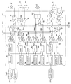
- Fig. 3 is a schematic block diagram showing the traction control section 30' of the
electronic control circuit 30 in Fig. 2 according to the first embodiment; - Fig. 4 is a timing chart showing, as an example, the control operation of the first embodiment;
- Fig. 5 is a block diagram showing the arrangement of the
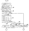
electronic control circuit 30 in Fig. 1 according to the second embodiment; - Fig. 6(A) and (B) are flowcharts showing, as an example, the control operation of the second embodiment;
- Fig. 7 is a timing chart showing, as an example, the control operation of the second embodiment;
- Embodiments of the present invention will now be described with reference to the drawings.
- In Fig. 2 showing generally a first embodiment of the inventive wheel slip control system, numeral 1 shows an internal combustion engine, 2 shows a fuel injection valve, 3 shows an intake air path, the
intake air path 3 is provided with afirst throttle valve 5 which interlocks to anaccelerator pedal 4 and a second throttle valve 7 which is driven by aDC motor 6 so as to adjust the intake air amount. Normally, said second throttle valve 7 is fully opened. It is controlled from the full open to the full close so as to control the power of the internal combustion engine for the traction control only. The slip control is executed when the valve is half-opened. - And the arrangement includes a brake pedal 11, a
brake master cylinder 12 serving as the first pressure source for providing a brake hydraulic pressure in response to a displacement of the brake pedal 11, a sub-master cylinder 13 serving as the second pressure source for providing a brake hydraulic pressure derived from the power steering hydraulic system upon detection of an acceleration slip as described later, non-driven right and left wheels 14 and 15 of the vehicle, driven right and leftwheels 16 and 17,wheel cylinders 18∼21 provided for the wheels 14∼17, a hydraulic system 23 used for anti-skid control, a power steeringhydraulic system 24 for both anti-skid and traction controls, a non-drivenwheel speed sensor 25 generating a pulse signal at frequencies in proportion to the rotational speed of the non-driven wheels 14 and 15, a driven-wheel speed sensor 26 generating a pulse signal at frequencies in proportion to the rotational speed of the drivenwheels 16 and 17, and anelectronic control circuit 30 implementing anti-skid control and traction control as well by controlling thehydraulic system 23 and 24. - The
brake master cylinder 12 is of a tandem master cylinder assembly, supplying a brake oil pressure to thewheel cylinders 18 and 19 on the non-driven wheels 14 and 15 in one hydraulic system, and to thewheel cylinders 20 and 21 of the drivenwheels 16 and 17 in another. The brake oil pressure produced by the sub-master cylinder 13 is used for the braking of drivenwheels 16 and 17, and as to which of this brake hydraulic pressure or that produced by thebrake master cylinder 2 is supplied by way of the anti-skid hydraulic system 23 to thewheel cylinders 20 and 21 is determined by achange valve 32 serving as the pressure source selection means. Thechange valve 32 has the structure of a shuttle valve, supplying the higher of the above two hydraulic pressures to the anti-skid hydraulic system 23. - The anti-skid hydraullic system 23 has major hydraulic paths for supplying the pressure from the
change valve 32 to thewheel cylinders 20 and 21 via a 3-position valve 34, and operates to increase the pressure by means of anoil pump 36 and hold or decrease (release the pressure to a reservoir 38) depending on the position of the 3-position valve 34. The system 23 further includescheck valves valve 41 being used to decrease the pressure (decrease the braking force) by the operation of the brake pedal when the 3-position valve 34 is set at "hold" position. The 3-position valve 34 is operated by theelectronic circuit 30, and positions a, b and c in Fig. 2 correspond to "increase pressure", "hold pressure" and "decrease pressure", respectively. - Next, the power steering
hydraulic system 24 will be described. The power steeringhydraulic system 24 consists of anoil pump 52 for pumping up the hydraulic oil used in the system from areservoir tank 51,check valves steering gear box 55, anoil pressure switch 56 which turns on (low level) when the oil pressure in thesteering gear box 55 increases due to steering operation, a 2-position valve 57 (will be termed M/C up=pressure valve hereinafter) having e position for supplying the oil pressure increased by the oil pump 52 (will be termed steering oil pressure hereinafter) only to the power steeringhydraulic system 24 and position f for supplying the oil to both of thesystem 24 and the traction control sub-master cylinder 13, and 2-position valve 58 (will be termed PS up-pressure valve hereinafter) having position h for supplying the hydraulic oil pumped by theoil pump 52 directly to thesteering gear box 55 and position i for supplying the hydraulic oil with increased pressure to thegear box 55. The position of the oil-pressure switch 56 is informed to theelectronic control circuit 30, and the M/C up-pressure valve 57 and PS up-pressure valve 58 are controlled by theelectronic control circuit 30. - Next, a section 30' of the
electronic control 30 for implementing traction control will be described with reference to Fig. 3. Besides the traction control circuit 30', theelectronic control circuit 30 includes the anti-skid control circuit (ES), but this section unrelated directly to the present invention will be disregarded in the following description. - Briefly, the traction control circuit 30' operates to receive the pulse signal from the non-driven
wheel speed sensor 25 on an F/V converter 70, differentiate its voltage output Vfr by adifferentiator 71 to obtain the acceleration of the vehicle, and compare the differentiated output with a zero level by acomparator 72 to obtain a signal Vfc indicative of as to whether the vehicle is in acceleration or deceleration. The signal Vfc is sent to the anti-skid control circuit ESC, which is activated when Vfc is at a low level. - Based on the signal Vfr representing the non-driven wheel speed, a threshold-1
generator 73a and anadder 74a in unison produce the first slip threshold level Vfbh, and a threshold-2generator 73b and anadder 74b in unison produce the second slip threshold level Vfbl, a threshold-3 generator 73c and anadder 74c in unison produce the third slip threshold level Vfsh, a threshold-4generator 73d and an adder 74d in unison produce the fourth slip threshold level Vfsℓ. - These voltage levels are compared by
comparators wheel sensor 26 and converted into voltage by an F/V converter 79, and four slip threshold signals Vcbℓ, Vcbh, Vcsh and Vcsℓ are obtained. The relationship among those signals is as follows.

As explained later in Fig. 4, the first and second slip threshold signals, Vfbh and Vfbℓ, are employed as threshold level for controlling the braking force by means of said anti-skid hydraulic system 23 and the third and forth slip threshold signals, Vfsh and Vfsℓ, as threshold level for controlling intake air amount of saidinternal combustion engine 1 by means of said second throttle valve 7. In addition, the first two signals Vcbh and Vcbl indicated comparison of the driven wheel speed Vrr with the first threshold level Vfbh and second threshold level Vfbl provided based on the non-driven wheel speed Vfr as shown in Fig. 4. The fourth slip threshold signal Vfsℓ gives a timing for the preparation of traction control, while the first slip threshold signal Vfbh gives a timing for carrying out traction control by increasing the brake oil pressure. - Also, the third slip threshold signal Vcsh generated by comparing the third slip threshold level Vfsh with the driving wheel speed indicates the timing when said throttle valve 7 is driven toward closing position by operating said
motor 6 in normal direction. On the other hand, the fourth slip threshold signal Vcsℓ generated by comparing the fourth slip threshold level Vfsℓ with the driven wheel speed indicates the timing when said throttle valve 7 is driven toward opening position by operating saidmotor 6 in the opposite direction. - The traction control circuit 30' further operates to differentiate the signal Vrr representing the driven wheel speed to obtain a signal Vrg representing the accelerating of the driven
wheels 16 and 17. The signal Vrg is compared with an output signal G1 from a threshold-5generator 84 and an output signal G2 from a threshold-6generator 85 bycomparators - The above three signal processing systems perform traction control as shown in Fig. 4.
- In operation, when the vehicle accelerates to have a high Vfc signal, a lower slip threshold signal Vfbℓ goes high, causing a
delay circuit 89 formed of a monostable multivibrator to produce a high output, and a 2-input ANDgate 90a produces a high output Vrt as shown in Fig. 4. This signal goes through a 2-input ORgate 91 and anamplifier 92 to activate theoil pump 36 in the anti-skid hydraulic system 23 and, at the same time, goes through anamplifier 90b to switch the M/C up-pressure valve 57 to position f so that an oil path for conducting the power steering oil pressure to the sub-master cylinder 13 is formed. With another condition that theoil pressure switch 56 is off at a high level added to the above condition, a 3-input ANDgate 90c provides an output Vrs, and when the Vrs becomes high, it goes through anamplifier 93 to switch the PS up-pressure valve 58 to position i and thesteering gear box 55 is throttled and the power steering hydraulic pressure is conducted to the sub-master cylinder 13. The purpose of entering then output of theoil pressure switch 56 to the 3-input ANDgate 90c is to switch the PS up-pressure valve 58 so as to prevent an unnecessary increase in the oil pressure which is raised automatically when the steering wheel is turned during traction control operation. The arrangement also works to supply the oil pressure to the power steering system in precedence over the traction control system. - The 3-
position valve 34 in the anti-skid hydraulic system 23 has its three positions a, b and c controlled in response to the state of a transistor Tr1 driven by the output of anamplifier 95 and the state of a transistor Tr2 provided with a current limiting resistor R and driven by the output of anotheramplifier 96. The valve position is determined by the combination of the transistor outputs as follows.Tr1 Tr2 Valve Position Brake Oil Pressure OFF OFF a Increase OFF ON b Hold ON ON c Decrease - The
amplifier 96 for driving the transistor Tr2 receives the output Vru of a 3-point ANDgate 97, which signal Vru is determined by the logical sum of the output of a 2-point NAND gate 98 receiving the supper slip threshold signal Vcbh and first slip control signal Vrgh, the signal Vrt, and the control signal from the anti-skid control circuit (ESC), as shown in Fig. 4. While, theamplifier 95 for driving the transistor Tr1 receives the output signal Vrd of a 2-input ORgate 99, which signal Vrd is determined by the logical sum of the output of a 2-input ANDgate 101 receiving the lower slip threshold signal Vcb1 inverted by an inverter 100 and the second slip control signal Vrgℓ, and the input signal from the ESC. - On the other hand, said second throttle valve 7 is controlled as follows by the third and fourth slip threshold signals Vcsh and Vcsℓ respectively. When the third and fourth slip threshold signals are in low level, the output of a 2-input NOR
gate 105 Vcsc becomes high level and a normal-reverse amplifier 107 feeds the current so as to operate saidmotor 6 in the opposite direction until said throttle valve 7 is fully opened. Consequently, said second throttle valve 7 is fully opened and the intake air amount is controlled by saidfirst throttle valve 5 interlocked to saidaccelerator pedal 4. When the fourth slip threshold signal Vcsℓ is high in level, the output of said 2-input NORgate 105 Vcsc becomes low level, thus, said normal-reverse amplifier 107 does not supply the power to saidmotor 6. Next, when the third slip threshold signal Vcsh is in high level, the output of said 2-input NORgate 105 Vcsc becomes low level, then said normal-reverse amplifier 107 supplies the power in the opposite direction compared with the former case so as to operate saidmotor 6 in normal direction until said second throttle valve 7 is fully closed. - As a result of the foregoing arrangement of this embodiment,
- (A) When the vehicle accelerates as detected on the non-driven wheels 14 and 15, the power steering oil pressure is high enough, the control operation proceeds as follows:
- (1) When the driven wheel speed Vrr has exceeded the lower threshold level Vfb1 based on the non-driven wheel speed, the
oil pump 36 in the anti-skid hydraulic system 23 is activated, and the M/C up-pressure valve 57 and PS up-pressure valve 58 in the power steeringhydraulic system 24 are switched to positions f and i, respectively; - (2) When the driven wheel speed Vrr has exceeded the third slip threshold level Vfsh based on the non-driven wheel speed, the power of said
internal combustion engine 1 is judged as unnecessarily large, thus, it is controlled by operating saidmotor 6 in normal direction and adjusting the position of said second throttle valve 7 toward the full close position. - (3) If the driven wheel speed Vrr exceeds the upper threshold level Vfbh based on the non-driven wheel speed and at the same time the driven wheel acceleration Vrg exceeds a certain reference level G1, the 3-
position valve 34 in the anti-skid hydraulic system 23 is set to position a (increase pressure) so as to increase the braking force of the drivenwheels 16 and 17; - (4) If the driven wheel speed Vrr is below the lower threshold level vfb1 based on the non-driven wheel speed and at the same time the driven wheel acceleration Vrg is below a certain reference level G2 (a negative value), the 3-
position valve 34 is set to position c (decrease pressure) so as to reduce the braking force; - (5) If the driven wheel speed Vrr is below the fourth slip threshold level Vfsℓ based on the non-driven wheel speed, the control of power of said
internal combustion engine 1 is regarded as unnecessary and the power is increased by operating saidmotor 6 in reverse direction and controlling the position of said second throttle valve 7 toward the full open; and - (6) The control is conducted so as to hold the braking force with the position of said 3-
position valve 34 set at position b (hold) under the conditions other than (3) and (4) mentioned above. On the other hand, the power of saidinternal combustion engine 1 is held without controlling the position of said second throttle valve 7 under the conditions except (2) and (5) mentioned above.
- (1) When the driven wheel speed Vrr has exceeded the lower threshold level Vfb1 based on the non-driven wheel speed, the
- (B) When a steering operation takes place, causing the oil pressure in the
steering gear box 55 to increase with theoil pressure switch 56 operating ON, the PS up-pressure valve 58 is restored to position h and the 3-position valve 34 is set to position a (increase pressure). Accordingly, if the drivenwheel 16 or 17 slips during the acceleration of the vehicle, the existing anti-skid hydraulic system sourced by the power steering hydraulic pressure is used to brake the drivenwheels 16 and 17 so as to prevent a slip running etc., whereby the drivenwheels 16 and 17 are exerted to produce an optimal traction force. - Also, in view of the power of said
internal combustion engine 1 being decreased by the second throttle valve 7, it is possible to prevent the lock of the drivenwheels 16 and 17, etc. and give them the optimum driving force by traction control. Therefore, as a whole, the traction control with the good efficiency can be achieved, employing the braking system in accordance with the hydraulic pressure of the anti-skid hydraulic system 23 for the quick response, and the second throttle valve 7 for controlling the rotation in comparatively longer period, respectively. - Additionally, as the power of the
internal combustion engine 1 is controlled by the second throttle valve 7, the necessary braking force for traction control is minimized and the reduction of the hydraulic system in size and weight is made possible. Also, the fuel consumption is improved because no extra fuel is supplied to theinternal combustion engine 1 when the braking force is generated, and at the same time, the exothermic of brake system which supplies the braking force can be prevented. - This traction control is easily implemented without the need of a specialized hydraulic system and devices, but by utilization of the hydraulic system used for the anti-skid operation, the 3-
position valve 34 used therein, and the power steering hydraulic system for obtaining the braking oil pressure independently of the driver's action. On this account, traction control can be established merely through a little modification for the piping and replacement of theelectronic control circuit 30 for a vehicle which already installs the anti-skid control and power steering systems. It should be noted in Fig. 3 that the remaining one input to the 2-input ORgates gate 97 respectively and to allow the anti-skid control circuit (ESC) to control the 3-position valve 34 andoil pump 36. Since anti-skid control and traction control do not take place concurrently, these systems can be shared by separate purposes through a simple logical sum process. - Next, the second embodiment of this invention will be described. The second embodiment is intended to control the hydraulic systems and associated devices similar to those of the first embodiment shown in Fig. 2 through an
electronic control circuit 30 which is in this case constituted mainly by a microcomputer as shown in Fig. 5. The control is executed according to the flowchart shown in Figs. 6 (A) and (B). The arrangement of Fig. 5 includes a central processing unit (CPU) 110 which is programmed to receive the sensor signals from the drivenwheel speed sensor 26, non-drivenwheel speed sensor 25 andoil pressure switch 56, and perform various calculations in response to these input signals. Other circuit components included are a read-only memory (ROM) 112 for storing the above-mentioned CPU control program, maps, and fixed data, a random access memory (RAM) 113 for performing reading and writing sensor input data temporarily, and calculation data, aninput interface circuit 114 including waveform shaping circuits and a multiplexer for supplying sensor input signals selectively to theCPU 110, anoutput circuit 116 for driving theoil pump 36, M/C up-pressure valve 57 and PS up-pressure valve 58 and also driving the 3-position valve 34 through transistors Tr1 and Tr2, and a bus line 118 for providing data communication between theCPU 110,ROM 112,RAM 113, and input/output interface circuits power supply circuit 120 for all of the above circuit components. - In addition, the 3-
position valve 34 and themotor 6 are constituted so as to be driven by the outputcircuit interface circuit 116 via transistors Tr1 and Tr2, a power restricting resistor R andPWM drive circuit 125 which conducts pulse width modulation respectively. - The traction control operation which is carried out together with anti-skid control on a time division basis by the
electronic control circuit 30 arranged as described above will be described in connection with the flowchart shown in Figs. 6 (A) and (B). - Though the flowcharts are drawn separately in the form of Figs. 6 (A) and (B) considering the size of drawing, a series of process is performed consistently. The routine of this traction control is performed every predetermined period together with the anti-skid control, etc. The process of every step will be described hereafter.
- Step 200: Read input data on the
input interface circuit 114 of the driven wheel speed vr from the drivenwheel sensor 26, the non-driven wheel speed vf from thenon-driven wheel sensor 25, and the switch state from theoil pressure switch 56. - Step 220: Perform differentiation process for the driven wheel speed vr to obtain acceleration α of the driven wheels.
- Step 230: Test whether the driven wheel acceleration is above zero (acceleration).
- Step 240: Calculate the slip thereshold levels vs1, vs2, vs3 and vs4 from the non-driven wheel speed vf using predetermined constants K1, K2, K3, K4 (K2>K3>K4>K1), g1, g2, g3 and g4 as follows.


Step 242: Decide whether the driven wheel speed is above the third slip threshold level vs3 or not. - Step 244: Decide whether the driven wheel speed is equal or below the fourth slip thereshold level vs4 or not.
- Slip 246: Output the normal signal via the
output interface circuit 116 so as to control the position of the second throttle valve 7 toward the full close position by operating themotor 6 with thePWM drive circuit 125 in normal rotation. - Step 247: Output the reverse signal via the
output interface circuit 116 so as to control the position of the throttle valve 7 toward the full open position by operating themotor 6 with thePWM drive circuit 125 in opposite rotation. - Step 248: Reset the output of the normal and the reverse signals mentioned above.
- Each step of the flowchart shown in Fig. 6 (A) has been explained above and that in Fig. 6 (B) will be described below.
- Step 250: Test whether the driven wheel speed vr is higher than the first thereshold level vs1.
- Step 260: Set a predetermined value to the counter C in the CPU.
- Step 270: Reset the counter C to zero.
- Step 280: Decrement the counter C by one.
- Step 290: Test whether the content of counter C is above zero. The counter C used in the steps 260-290 is actually a programmed operation substituting the
delay circuit 89 in the first embodiment, and its purpose is to continue traction control for a preset time length when the speed vr of drivenwheels 16 and 17 has fallen below the first threshold level vs1 after traction control had been commenced. - Step 293: Test whether the
oil pressure switch 56 is OFF. If the switch is OFF, indicating the steering operation being inert and the power steering hydraulic pressure not being increased, the sequence proceeds to step 350. - Step 296: If the
oil pressure switch 56 is found ON instep 293, indicating the steering operation, the PS up-pressure valve 58 is reset to position h. - Step 300: Set or hold the M/C up-
pressure valve 57 in the power steeringhydraulic system 24 to position f, and activate theoil pump 36. - Step 303: Test whether the
oil switch 56 is OFF. - Step 306: If the
oil pressure switch 56 is OFF, switch the PS up-pressure valve 58 to position i so as to increase the oil pressure conducted to the sub-master cylinder 13. - Step 309: If the
oil pressure switch 56 is ON, switch the PS up-pressure valve 58 to position h. - Step 310: Test whether the driven wheel speed vr is higher than the second threshold level vs2.
- Step 320: Reset or hold the M/C up-
pressure valve 57 and PS up-pressure valve 58 to positions e and h, respectively, and deactivate theoil pump 36. - Step 330: Set or hold the 3-
position valve 34 in the anti-skid hydraulic system 23 to position a (increase pressure) - Step 340: Set the 3-
position valve 34 to position b (hold pressure). - Step 350: Set the 3-
position valve 34 to position c (decrease pressure). - According to this embodiment, as shown in Fig. 7,
- (A) When the driven
wheels 16 and 17 are found accelerating (α=0), i.e., an affirmative decision made bystep 230, the control operation takes place as follows.- (1) When the driven wheel speed vr has exceeded the third slip threshold level vs3 based on the non-driven wheel speed vf, i.e., an affirmative decision made by
step 242, themotor 6 is operated in normal rotation so as to control the position of the second throttle valve 7 toward the full close position and the intake air amount of theinternal combustion engine 1 is decreased so as to control the output (See period CL in Fig. 7). - (2) When the driving wheel speed vr has fallen below the fourth slip threshold level vs4 by the control mentioned in (1) or (5) hereafter, i.e., an affirmative decision made by
step 244, themotor 6 is operated in opposite rotation so as to control the second throttle valve 7 toward the full open position and the intake air amount of theinternal combustion engine 1 is increased so as to increase the output (See period OP in Fig. 7). - (3) When the relation of the driven wheel speed vr and the fourth slip thereshold level is vs4 < vr < vs3, i.e., a negative decision made by both
steps - (4) When the driven wheel speed vr has exceeded the first thereshold level vs1 based on the non-driven wheel speed vf, i.e., an affirmative decision made by
step 250, theoil pump 34 in the anti-skid hydraulic system 23 is activated, the M/C up-pressure valve 57 in the power steeringhydraulic system 24 is set to position f, and the 3-position valve 34 in the anti-skid hydraulic system 23 is set to position b (hold pressure). (See period I in Fig. 7.)
In the above operation, if theoil pressure switch 56 is OFF, the PS up-pressure valve 58 is set to position i (steps 303 and 306), or if theoil pressure switch 56 is ON, the PS up-pressure valve 58 is set to position h (steps 303 and 309). - (5) When the driven wheel speed vr has exceeded the second threshold level vs2, i.e., an affirmative decision made by
step 310, the 3-position valve 34 is set to position a (increase pressure) so as to increase the braking force of the driven wheels. (See period II in Fig. 7.) - (6) Following the above state (4) or (5), when the driven wheel speed vr has fallen below the first threshold level vs1, i.e., a negative decision made by
step 250 and an affirmative decision made bystep 290, the 3-position valve 34 is set to position c (decrease pressure) so as to reduce the braking force. (See period III in Fig. 7.) At this time, if theoil pressure switch 56 is found ON, the PS up-pressure valve 58 is reset to position h (steps 293 and 296). - (7) When the time length set in the counter C has expired (a negative decision made by step 290), while the driven wheel speed vr staying below the first threshold level vs1, the M/C up-
pressure valve 57 and PS up-pressure valve 58 are set to positions e and h, respectively, theoil pump 34 is deactivated, and the 3-position valve 34 is switched to position a (increase pressure) to complete the traction control operation (the period not shown in Fig. 7.)
- (1) When the driven wheel speed vr has exceeded the third slip threshold level vs3 based on the non-driven wheel speed vf, i.e., an affirmative decision made by
- (B) If the vehicle acceleration α falls below zero, i.e., deceleration begins, (a negative decision made by step 230), the counter C is reset to zero, and the same control as above (4) takes place. (See period IV in Fig. 7.)
- Accordingly, this embodiment performs identically to the first embodiment and has the same effects as those of the first embodiment, for example, the quick response achieved by the anti-skid hydraulic system 23, the reduction of fuel consumption by the second throttle valve 7, etc. and moreover, the use of the
CPU 110 allows various schemes of traction control without changing the hardware structure of theelectronic control circuit 30.
Claims (9)
- A wheel slip control system used for a vehicle comprising:(a) a brake slip detection means (25, 26) for detecting a state of slipping of wheels (14, 15, 16, 17) during a braking operation of said vehicle and providing a brake slip signal representing the state of slipping,(b) a first electronic control means (ESC) receiving said brake slip signal and providing a first adjustment signal which controls a driven wheel speed (Vrr),(c) an acceleration slip detection means (25, 26) for detecting a state of slipping of said wheels during an accelerating operation of said vehicle and for providing acceleration slip signals (Vcbh, Vcbl, Vrgh, Vrgl) for traction control, and acceleration slip signals (Vcsh, Vcsl) for engine output control,(d) a second electronic control means (30) receiving said acceleration slip signals for traction control (Vcbh, Vcbl, Vrgh, Vrgl) to provide a second adjustment signal (Vesc), and for receiving said acceleration slip signals for engine output control (Vcsh, Vcsl) to provide a third adjustment signal (Vcsc) which controls a drive means (6) of a throttle valve (7),(e) a control line connecting said second electronic control means (30) to said drive means (6) for controlling said drive means (6) of said throttle valve (7) being placed at an intake path (3) by said third adjustment signal (Vcsc),(f) a hydraulic control means (23) for receiving either said first adjustment signal for controlling said driven wheel speed (Vrr) or said second adjustment signal (Vesc) for said traction control, and for controlling slip of said driven wheels (16, 17),
said wheel slip control system being characterized in that(g1) said second electronic control means (30) controls said hydraulic control means (23) in accordance with said second adjustment signal (Vesc) to provide an immediate fine traction control by applying a brake pressure when the detected wheel slip rate exceeds a predetermined first threshold value (Vfbh), and(g2) starts to control said throttle valve (7) by said third adjustment signal (Vcsc) to provide said engine output control when a slip rate exceeds a predetermined third threshold value (Vfsh), wherein the first threshold value (Vfbh) represents a higher slip rate than the third threshold value (Vfsh). - A wheel slip control system according to claim 1, being characterized by further comprising a pressure source selection means (32) receiving a first pressure of a first pressure source (11, 12), and a second pressure of a second pressure source (24) to measure said difference of said two pressures, and adapted to select one of said first and second pressure sources depending on said measured differential pressure, and said first pressure source (11, 12) comprises a brake pedal (11) and a master cylinder (12) producing a pressure in proportion to said displacement of said brake mechanism (11).
- A wheel slip control system according to claim 2, being characterized in that said second pressure source (24) comprises a power steering control pressure system, a switch valve (57, 58) for adjusting a pressure produced by said power steering control pressure system, and a submaster cylinder (13) supplying a pressure provided by said switch valve (57, 58) to said pressure source selection means (32).
- A wheel slip control system according to claim 2, being characterized in that said pressure source selection means (32) comprises a change valve (32) which supplies one of said first and second pressure sources having higher pressure based on said difference between said first and second pressures.
- A wheel slip control system according to claim 1, being characterized in that said hydraulic control means (23) comprises an anti-skid control pressure unit, including a three-position valve (34) which operates on said pressure from said pressure source selection means (32) to be held decreased, or increased in accordance with either said first adjustment signal or said second adjustment signal (Vesc).
- A wheel slip control system according to claim 1, being characterized in that said brake slip detection means (25, 26) and said acceleration slip detection means (25, 26) comprise a driven wheel speed sensor (26) and a non-driven speed sensor (25).
- A wheel slip control system according to claim 5, being characterized in that said electronic control means (30) operates on said three-position valve (34) to decrease said pressure applied to said driven wheel, to increase said pressure, and to hold said pressure in accordance with said second adjustment signal (Vesc).
- A wheel slip control system according to claim 5, being characterized in that said throttle valve (7) is a second throttle valve provided near a first throttle valve (5) interlocked to an acceleration increase mechanism (4) being placed at an intake path (3), where said electronic control means (30) controls said throttle valve (7) in accordance with the third adjustment signal (Vcsc) based on an upper limit (Vfsh) and a lower limit (Vfsl) of said driven wheel speed (Vrr).
- A wheel slip control system according to claim 1, being characterized by further comprising a pressure source selection means (32) receiving a first pressure of a first pressure source (11, 12), and a second pressure of a second pressure source (24), and adapted to forcibly select one of said first and second pressure source depending on said control of said first electronic control means (ESC) and said second electronic control means (30), and said first pressure source (11, 12) comprises a brake pedal (11) and a master cylinder (12) producing a pressure in proportion to said displacement of said brake pedal (11).
Applications Claiming Priority (2)
| Application Number | Priority Date | Filing Date | Title |
|---|---|---|---|
| JP228537/84 | 1984-10-30 | ||
| JP59228537A JPH0626945B2 (en) | 1984-10-30 | 1984-10-30 | Vehicle slip control device |
Publications (3)
| Publication Number | Publication Date |
|---|---|
| EP0180096A2 EP0180096A2 (en) | 1986-05-07 |
| EP0180096A3 EP0180096A3 (en) | 1989-05-31 |
| EP0180096B1 true EP0180096B1 (en) | 1994-01-12 |
Family
ID=16877950
Family Applications (1)
| Application Number | Title | Priority Date | Filing Date |
|---|---|---|---|
| EP85113148A Expired - Lifetime EP0180096B1 (en) | 1984-10-30 | 1985-10-16 | Wheel slip control system |
Country Status (4)
| Country | Link |
|---|---|
| US (1) | US4681374A (en) |
| EP (1) | EP0180096B1 (en) |
| JP (1) | JPH0626945B2 (en) |
| DE (1) | DE3587723T2 (en) |
Families Citing this family (30)
| Publication number | Priority date | Publication date | Assignee | Title |
|---|---|---|---|---|
| JPS61199401A (en) * | 1985-02-27 | 1986-09-03 | Nippon Air Brake Co Ltd | Skid detecting method |
| SE453277B (en) * | 1986-03-03 | 1988-01-25 | Bror Lennart Anders Swiden | METHOD OF AUTOMATICALLY POWERING A VEHICLE WHEEL BRAKE INTENDED TO PREVENT THE WHEEL TO SLIDE AND DEVICE FOR EXECUTING THE METHOD |
| JPH0620877B2 (en) * | 1986-04-23 | 1994-03-23 | トヨタ自動車株式会社 | Vehicle acceleration slip control method |
| CA1306784C (en) * | 1986-06-09 | 1992-08-25 | Masakazu Sakaguchi | Method for controlling slip of a driving wheel of a vehicle |
| US4866618A (en) * | 1986-07-03 | 1989-09-12 | Nissan Motor Co., Ltd. | Engine control system for automotive vehicle |
| JP2590825B2 (en) * | 1986-07-12 | 1997-03-12 | トヨタ自動車株式会社 | Manual / Electric dual brake system |
| US4884651A (en) * | 1986-07-24 | 1989-12-05 | Mazda Motor Corporation | Vehicle slip control apparatus |
| DE3633687A1 (en) * | 1986-10-03 | 1988-04-14 | Bosch Gmbh Robert | AUTOMATIC SLIP CONTROL UNIT |
| JP2630586B2 (en) * | 1986-10-24 | 1997-07-16 | 日本エ−ビ−エス株式会社 | Vehicle brake adjustment device |
| JP2512918B2 (en) * | 1986-12-05 | 1996-07-03 | 日本電装株式会社 | Stepping motor and engine intake air amount control device |
| JP2504009B2 (en) * | 1986-12-13 | 1996-06-05 | トヨタ自動車株式会社 | Acceleration slip control device |
| JPS63306253A (en) * | 1987-06-04 | 1988-12-14 | Akebono Brake Res & Dev Center Ltd | Acceleration slip controller for wheel |
| US4865397A (en) * | 1987-07-22 | 1989-09-12 | Toyota Jidosha Kabushiki Kaisha & Nippondenso Co., Ltd. | Anti-lock braking system for a vehicle having a traction control module |
| JPH0623029B2 (en) * | 1987-07-30 | 1994-03-30 | マツダ株式会社 | Anti-slip device for vehicle with automatic transmission |
| WO1989004263A1 (en) * | 1987-11-06 | 1989-05-18 | Robert Bosch Gmbh | Drive slip regulating system |
| JP2704623B2 (en) * | 1988-02-12 | 1998-01-26 | 曙ブレーキ工業株式会社 | Anti-lock control method |
| US4926333A (en) * | 1988-04-20 | 1990-05-15 | Mitsubishi Jidosha Kogyo Kabushiki Kaisha | Traction control apparatus |
| JP2773774B2 (en) * | 1989-03-31 | 1998-07-09 | マツダ株式会社 | Automotive slip control device |
| IT1233206B (en) * | 1989-04-18 | 1992-03-20 | Fiat Auto Spa | SYSTEM AND PROCEDURE FOR CHECKING THE OPERATION OF AN ANTI-LOCK BRAKING DEVICE FOR FULL-DRIVE VEHICLES |
| JPH02310165A (en) * | 1989-05-24 | 1990-12-25 | Mitsubishi Electric Corp | Anti-skid control device |
| DE3931315A1 (en) * | 1989-09-20 | 1991-03-28 | Bosch Gmbh Robert | ANTI-BLOCKING CONTROL SYSTEM |
| JPH03284429A (en) * | 1990-03-30 | 1991-12-16 | Mazda Motor Corp | Slip controller for vehicle |
| US5107429A (en) * | 1990-06-11 | 1992-04-21 | Ford Motor Company | Adaptive throttle controller for vehicle traction control |
| US5297857A (en) * | 1991-05-31 | 1994-03-29 | Allied-Signal Inc. | Direct acting electro-hydraulic braking system with regulated leak rate |
| EP1747131B1 (en) * | 2004-05-20 | 2012-08-29 | Honda Motor Co., Ltd. | Cooperative traction control system |
| DE102009021012A1 (en) * | 2008-05-14 | 2009-11-19 | Robert Bosch Gmbh | Hydraulic brake system and pilot unit for such a brake system |
| US20130238216A1 (en) * | 2010-10-29 | 2013-09-12 | Advics Co., Ltd. | Vehicle control apparatus and vehicle control method |
| KR101979413B1 (en) * | 2014-06-17 | 2019-05-16 | 주식회사 만도 | Brake traction control system in a vehicel and control method thereof |
| JP2019196029A (en) * | 2018-05-07 | 2019-11-14 | ロベルト・ボッシュ・ゲゼルシャフト・ミト・ベシュレンクテル・ハフツングRobert Bosch Gmbh | Fluid pressure control unit |
| CN108749796B (en) * | 2018-08-29 | 2023-11-10 | 燕山大学 | Full-hydraulic automatic detection control anti-slip system and anti-slip method thereof |
Citations (1)
| Publication number | Priority date | Publication date | Assignee | Title |
|---|---|---|---|---|
| DE3127302A1 (en) * | 1981-07-10 | 1983-01-27 | Daimler Benz Ag | "DEVICE FOR CONTROLLING THE DRIVE IN MOTOR VEHICLES" |
Family Cites Families (18)
| Publication number | Priority date | Publication date | Assignee | Title |
|---|---|---|---|---|
| US3467443A (en) * | 1967-08-17 | 1969-09-16 | Nippon Denso Co | Antiskid apparatus for automotive vehicles |
| FR1559013A (en) * | 1967-12-27 | 1969-03-07 | ||
| DE1755302A1 (en) * | 1968-04-24 | 1971-07-15 | Daimler Benz Ag | Device for controlling two valves to prevent the brakes from locking |
| US3893535A (en) * | 1968-11-02 | 1975-07-08 | Daimler Benz Ag | Installation for preventing spinning of the driven wheels of a motor vehicle |
| US3666328A (en) * | 1970-10-09 | 1972-05-30 | Gen Motors Corp | Wheel anti-lock control system |
| US3779331A (en) * | 1971-09-28 | 1973-12-18 | Daimler Benz Ag | Device for prevention of spinning of the driven wheels of a motor vehicle |
| DE2148302A1 (en) * | 1971-09-28 | 1973-04-05 | Daimler Benz Ag | DEVICE TO PREVENT THE SPINNING OF THE DRIVEN WHEELS OF A VEHICLE |
| US3861758A (en) * | 1973-09-25 | 1975-01-21 | Bendix Corp | Adaptive braking system |
| US3938611A (en) * | 1973-11-23 | 1976-02-17 | Kelsey-Hayes Company | Intake manifold valve throttle control for spin control system |
| US3993364A (en) * | 1975-02-18 | 1976-11-23 | Sanwa Seiki Mfg. Co. Ltd. | Anti-skid device for use with vehicle brake systems |
| US3963277A (en) * | 1975-02-18 | 1976-06-15 | Sanwa Seiki Mfg. Co. Ltd. | Vehicle brake system |
| US4402047A (en) * | 1980-12-16 | 1983-08-30 | General Signal Corporation | Computerized brake control system |
| DE3205627A1 (en) * | 1981-04-30 | 1982-11-18 | Robert Bosch Gmbh, 7000 Stuttgart | DRIVE SLIP CONTROL |
| JPS5835240A (en) * | 1981-08-27 | 1983-03-01 | Nissan Motor Co Ltd | Control mechanism of fuel supply device in engine |
| GB2111149B (en) * | 1981-09-18 | 1985-06-26 | Daimler Benz Ag | Charging a pressure accumulator in anti-skid and anti-spin brake system |
| DE3140959C2 (en) * | 1981-10-15 | 1983-12-22 | Daimler-Benz Ag, 7000 Stuttgart | Propulsion control device for a motor vehicle, which is also equipped with an anti-lock braking system |
| JPS592962A (en) * | 1982-06-25 | 1984-01-09 | Nippon Air Brake Co Ltd | Anit-skid liquid pressure controller |
| GB2130757B (en) * | 1982-10-12 | 1987-05-07 | Honda Motor Co Ltd | Anti-slip systems for wheeled vehicles |
-
1984
- 1984-10-30 JP JP59228537A patent/JPH0626945B2/en not_active Expired - Lifetime
-
1985
- 1985-10-16 EP EP85113148A patent/EP0180096B1/en not_active Expired - Lifetime
- 1985-10-16 DE DE3587723T patent/DE3587723T2/en not_active Expired - Lifetime
- 1985-10-23 US US06/790,453 patent/US4681374A/en not_active Expired - Lifetime
Patent Citations (1)
| Publication number | Priority date | Publication date | Assignee | Title |
|---|---|---|---|---|
| DE3127302A1 (en) * | 1981-07-10 | 1983-01-27 | Daimler Benz Ag | "DEVICE FOR CONTROLLING THE DRIVE IN MOTOR VEHICLES" |
Also Published As
| Publication number | Publication date |
|---|---|
| JPS61108039A (en) | 1986-05-26 |
| JPH0626945B2 (en) | 1994-04-13 |
| EP0180096A3 (en) | 1989-05-31 |
| DE3587723D1 (en) | 1994-02-24 |
| DE3587723T2 (en) | 1994-08-04 |
| US4681374A (en) | 1987-07-21 |
| EP0180096A2 (en) | 1986-05-07 |
Similar Documents
| Publication | Publication Date | Title |
|---|---|---|
| EP0180096B1 (en) | Wheel slip control system | |
| EP0180095B1 (en) | Wheel slip controlling system for a vehicle | |
| US4850656A (en) | Anti-slip control device for drive wheels of automotive vehicle | |
| US5822709A (en) | Vehicle attitude control system having vehicle decelerating device operated before operation of vehicle attitude control device | |
| US5320422A (en) | Slip control device for vehicle wheel | |
| US4739856A (en) | Wheel slip control system for a vehicle | |
| US4967866A (en) | Traction control system for motor vehicles | |
| EP0176785B1 (en) | Wheel slip controlling system | |
| US4681373A (en) | Wheel slip control system | |
| US5193888A (en) | Slip control system for motor vehicle | |
| JP3136720B2 (en) | Traction control device for vehicles | |
| US6371234B2 (en) | Vehicle stability control apparatus and method | |
| US6050655A (en) | Antiskid brake controller | |
| US4854411A (en) | Device for determining whether a motor vehicle is on an uphill road upon starting of the vehicle | |
| JPH07156780A (en) | Brake pad temperature estimating device and wheel slip controller using the same | |
| US6381531B1 (en) | Process and device for adjusting the braking effect in a vehicle | |
| JPH07112634A (en) | Wheel slip control device | |
| JP3772486B2 (en) | Anti-skid control device | |
| JP2964755B2 (en) | Traction control device for vehicles | |
| EP0405984B1 (en) | Traction control method for vehicle | |
| JP3314551B2 (en) | Braking force control device | |
| JP2002517351A (en) | Method and apparatus for traction slip control of a vehicle on a road with different coefficient of friction in the lateral direction | |
| JPH07125561A (en) | Wheel slip controller | |
| JP2882151B2 (en) | Traction control device for vehicles | |
| JPH0747948A (en) | Anti-skid brake control and traction control method |
Legal Events
| Date | Code | Title | Description |
|---|---|---|---|
| PUAI | Public reference made under article 153(3) epc to a published international application that has entered the european phase |
Free format text: ORIGINAL CODE: 0009012 |
|
| AK | Designated contracting states |
Kind code of ref document: A2 Designated state(s): DE GB |
|
| PUAL | Search report despatched |
Free format text: ORIGINAL CODE: 0009013 |
|
| AK | Designated contracting states |
Kind code of ref document: A3 Designated state(s): DE GB |
|
| 17P | Request for examination filed |
Effective date: 19891027 |
|
| 17Q | First examination report despatched |
Effective date: 19910115 |
|
| GRAA | (expected) grant |
Free format text: ORIGINAL CODE: 0009210 |
|
| AK | Designated contracting states |
Kind code of ref document: B1 Designated state(s): DE GB |
|
| REF | Corresponds to: |
Ref document number: 3587723 Country of ref document: DE Date of ref document: 19940224 |
|
| PLBE | No opposition filed within time limit |
Free format text: ORIGINAL CODE: 0009261 |
|
| STAA | Information on the status of an ep patent application or granted ep patent |
Free format text: STATUS: NO OPPOSITION FILED WITHIN TIME LIMIT |
|
| 26N | No opposition filed | ||
| REG | Reference to a national code |
Ref country code: GB Ref legal event code: 746 Effective date: 19950807 |
|
| REG | Reference to a national code |
Ref country code: GB Ref legal event code: IF02 |
|
| PGFP | Annual fee paid to national office [announced via postgrant information from national office to epo] |
Ref country code: GB Payment date: 20041013 Year of fee payment: 20 |
|
| PGFP | Annual fee paid to national office [announced via postgrant information from national office to epo] |
Ref country code: DE Payment date: 20041014 Year of fee payment: 20 |
|
| PG25 | Lapsed in a contracting state [announced via postgrant information from national office to epo] |
Ref country code: GB Free format text: LAPSE BECAUSE OF EXPIRATION OF PROTECTION Effective date: 20051015 |
|
| REG | Reference to a national code |
Ref country code: GB Ref legal event code: PE20 |