EP0179457B1 - Ink dot printer - Google Patents
Ink dot printer Download PDFInfo
- Publication number
- EP0179457B1 EP0179457B1 EP85113459A EP85113459A EP0179457B1 EP 0179457 B1 EP0179457 B1 EP 0179457B1 EP 85113459 A EP85113459 A EP 85113459A EP 85113459 A EP85113459 A EP 85113459A EP 0179457 B1 EP0179457 B1 EP 0179457B1
- Authority
- EP
- European Patent Office
- Prior art keywords
- needle
- ink
- recorded medium
- tip
- normal position
- Prior art date
- Legal status (The legal status is an assumption and is not a legal conclusion. Google has not performed a legal analysis and makes no representation as to the accuracy of the status listed.)
- Expired
Links
Images

Classifications
-
- B—PERFORMING OPERATIONS; TRANSPORTING
- B41—PRINTING; LINING MACHINES; TYPEWRITERS; STAMPS
- B41J—TYPEWRITERS; SELECTIVE PRINTING MECHANISMS, i.e. MECHANISMS PRINTING OTHERWISE THAN FROM A FORME; CORRECTION OF TYPOGRAPHICAL ERRORS
- B41J2/00—Typewriters or selective printing mechanisms characterised by the printing or marking process for which they are designed
- B41J2/22—Typewriters or selective printing mechanisms characterised by the printing or marking process for which they are designed characterised by selective application of impact or pressure on a printing material or impression-transfer material
- B41J2/23—Typewriters or selective printing mechanisms characterised by the printing or marking process for which they are designed characterised by selective application of impact or pressure on a printing material or impression-transfer material using print wires
- B41J2/305—Ink supply apparatus
-
- B—PERFORMING OPERATIONS; TRANSPORTING
- B41—PRINTING; LINING MACHINES; TYPEWRITERS; STAMPS
- B41J—TYPEWRITERS; SELECTIVE PRINTING MECHANISMS, i.e. MECHANISMS PRINTING OTHERWISE THAN FROM A FORME; CORRECTION OF TYPOGRAPHICAL ERRORS
- B41J2/00—Typewriters or selective printing mechanisms characterised by the printing or marking process for which they are designed
- B41J2/22—Typewriters or selective printing mechanisms characterised by the printing or marking process for which they are designed characterised by selective application of impact or pressure on a printing material or impression-transfer material
- B41J2/23—Typewriters or selective printing mechanisms characterised by the printing or marking process for which they are designed characterised by selective application of impact or pressure on a printing material or impression-transfer material using print wires
- B41J2/235—Print head assemblies
- B41J2/25—Print wires
- B41J2/255—Arrangement of the print ends of the wires
Definitions
- This invention relates to an ink dot printer which comprises at least one needle capable of being displaced between a normal position remote from a recorded medium and a projected position close to the recorded medium, and drive means for moving the needle between the normal position and projected position and in which ink is supplied to and attached on the tip of the needle which faces the recording means when the needle is at the normal position.
- the ink is forcibly removed from the tip of the needle toward the recorded medium to form an ink dot on the recorded medium when the needle is at the projected position, an aggregate of such ink dots serving to form a character or a figure on the recorded medium.
- the usual ink dot printer of the type described above is provided with ink film forming means serving as ink supply means.
- the ink film forming means comprises a pair of magnetic plates extending parallel to each other and forming a vertical slit therebetween, an ink tank containing magnetic ink in which the lower ends of the paired magnetic plates are immersed, and exciting means for exciting the pair of magnetic plates to let the magnetic ink be withdrawn from the ink tank along the slit so as to form a magnetic ink film in the slit.
- the tip of the needle is placed in the slit when the needle is in the normal position, and magnetic ink from the magnetic ink film in the slit is attached to the tip of the needle.
- the needle In an ink dot printer of this type, the needle is moved from the normal position to the projected position to cause the tip of the needle to strike a recording sheet serving as a recorded medium and lying on a platen, thereby forming an ink dot on the recording sheet.
- the striking of the recording sheet by the needle however, produces a tremendous amount of noise.
- EP-A-0 128 558 (Art 54(3) EPC) such noise is prevented by stopping the needles at a position spaced from the recording sheet.
- the ink adhering to the needle tips is splashed therefrom onto the recording sheet thanks to the inertia in the ink, which occurs when the needles collide with the stoppers, and thanks to a magnetic force produced between said needle tips and the magnetic platen.
- This invention has been developed in light of the above, and its object is to provide an ink dot printer which can reliably and clearly form an ink dot on a recorded medium without generating any amount of noise.
- an ink dot printer which comprises at least one needle located in one side of a recorded medium and capable of being displaced between a normal position remote from the recorded medium and a projected position close to the recorded medium, and drive means for moving the at least one needle between the normal position and projected position, and in which ink is supplied to and attached to the tip of the needle which faces the recorded medium, when the needle is at the normal position, and ink is cause to be removed from the tip of the needle toward the recorded medium to form an ink dot on the recorded medium, when the needle is at the projected position, characterized in that: the needle is made of an electrically conductive material; and the ink dot printer further comprises an electrode disposed on another side of the recorded medium and facing the tip of the at least one needle, and electric field generating means for generating, between the electrode and needle, an electric field having such an intensity as to cause ink to fly from the tip of the needle, when the needle is closer to the recorded medium than in the normal position but still in spaced relationship thereto
- the ink supply means includes ink film forming means for forming an ink film in which the tip of the needle is immersed to let ink be attached to the tip of the needle when the needle locates at the normal position
- the needle is disposed at the normal position such that the tip end surface of the tip is in contact with the inner surface of the ink film which locates on the side of the recorded medium or slightly projects from the inner surface of the ink film so as to receive ink from the ink film by means of the surface tension in the inner surface.
- the amount of ink utilized for the formation of an ink dot on the recorded medium varies with the position of the tip of the needle in the ink film. If the tip of the needle which locates at the normal position breaks the inner surface of the ink film which locates on the side of the recorded medium and projects toward the recorded medium, the amount of ink attached to the tip of the needle will, desirably, be insufficient to result in the blurring of an ink dot formed on the recorded medium. On the other hand, if the distance between the tip of the needle which locates at the normal position and the inner surface of the ink film is increased in the direction away from the recorded medium, the amount of ink attached to the tip of the needle is increased. Consequently, an ink drop caused to fly from the needle at the projected position will be spattered as it contacts the recorded medium. In this latter case, it is difficult to form a satisfactory ink dot on the recorded medium.
- the tip of the needle is in contact with the inner surface of the ink film which locates on the side of the recorded medium or slightly projects from the inner surface of the ink film, the amount of ink attached to the tip of the needle can be standardized, making it possible to eliminate the splashing of ink caused between two adjacent needles by their displacement.
- the ink supply means includes ink film forming means for forming an ink film in which the tip of the needle is immersed to let ink be attached to the tip of the needle when the needle locates at the normal position
- the ink film forming means includes a pair of magnetic plates extending parallel to each other and forming a vertical slit therebetween, an ink tank containing magnetic ink in which the lower ends of the pair of magnetic plates are immersed, and exciting means for exciting the pair of magnetic plates to let the magnetic ink be withdrawn from the ink tank along the slit so as to form a magnetic ink film in the slit
- the needle is made of a non-magnetic material having electrical conductivity.
- the needle When the needle is made of a magnetic material, it is magnetized by the magnetic field in the slit between the pair of magnetic plates, so that magnetic ink is held magnetically by the magnetized needle. In such a case, it is difficult to cause magnetic ink to fly from the tip of the magnetized needle at the projected position toward the recorded medium. Besides, it is difficult to discharge magnetic ink from the slit between the pair of magnetic plates when the printer has been out of use for a long time.
- Fig. 1 shows an embodiment of the ink dot printer according to the invention.
- the illustrated ink dot printer has a housing 10 which accommodates a carriage shaft 12 and a guide shaft 14 that extend parallel to each other.
- a carriage 16 is mounted for reciprocal movement on the carriage shaft 12 and guide shaft 14.
- a printing head 20 facing a recording sheet 18 which serves as a recorded medium is mounted on the carriage 16.
- the printing head 20 has a head support 24 having bolt holes 22 for receiving bolts for bolting the printing head 20 to the carriage 16.
- a rear circular portion 28 of the head cover 26 accommodates needle drive means 30, as shown in Fig. 3.
- the needle drive means 30 has a magnetic member 34 which is made of a magnetic material and is bonded to a stepped portion of the head cover 26, as shown in Fig. 3.
- the magnetic member 34 has a partition wall 32 of a flat shape.
- the partition wall 32 as shown in Figs. 3 and 4, has a plurality of cores 38 which are in a circular arrangement and each of which carries a coil 36 wound thereon.
- the magnetic member 34 further has yokes 40 located outside of the cores 38 in the radial direction.
- the coils 36 are energized by a printing signal provided from control means (not shown). In this embodiment, the voltage applied to the coils 36 is from about 12 to about 13 volts.
- the base portion of an armature 42 is rotatably mounted on the each yoke 40 so as to make the armature 42 face the corresponding core 38, as shown in Fig. 3.
- the base end of a needle 44 is fixed to the free end portion of the each armature 42 through insulation means for preventing a failure of electrical insulation between the needle 44 and the armature 42.
- the fixed point of the free end portion to which the base end of the needle 44 is fixed is made of electricaly insulation material and the number of the needle 44 is nine.
- the needle 44 is made of a nonmagnetic material having electrical conductivity, e.g., stainless steel.
- the diameter of the needle 44 is approximately 0.2 mm. As shown in Fig.
- a needle spring 46 is wound around the needle 44 between the partition wall 32 of the magnetic member 34 and the armature 42.
- the needle spring 46 urges the armature 42, together with the needle 44, toward the reaward of the head cover 26 (i.e., to the left in Fig. 3).
- the nine needles 44 penetrate through holes 48 formed ⁇ i1 a circular arrangement in the partition wall 32 of the magnetic member 34, as shown in Fig. 4.
- These needles 44 further penetrate an intermediate guide 50 and an free end guide 52 provided in the head cover 26 and the free ends of these needles 44 reach ink film forming means 54 which serves as ink supply means, as shown in Fig. 3.
- the inkfilm forming means 54 includes a pair of vertically disposed magnetic plates 58 and 59 extending parallel to each other to form a vertical slit 26 (see Fig. 2) between them.
- the ink film forming means 54 further includes an electro magnet 60 serving as exciting means.
- the electro magnet 60 is disposed on top of the head cover 26 and is coupled to the rear ends of the pair of magnetic plates 58 and 59 which extend rearward along the both side surfaces of the head cover 26.
- the circular portion 28 of the head cover 26, as shown in Fig. 3, further accommodates a return spring 62 urging the armature 42 in the returning direction, and a stop 64 which determines the return position of the armature 42.
- a printed wiring board 68 is fixed to the head cover 26.
- the printed wiring board 68 has an electric circuit for controlling the energization of the coil 36, and is provided with a connector 66.
- the ink film forming means 54 further includes an ink tank 70 made of a synthetic resin.
- the ink tank 70 is fixed to the underside of a front end portion of the head cover 26.
- An ink impregnation member 72 is mounted in the ink tank 70 and magnetic ink 74 is stored in the ink tank 70.
- a hole 76 is formed at the top of the ink tank 70. Lower end portions of the pair of magnetic plates 58 and 59 are inserted into the hole 76 and immersed in the magnetic ink 74.
- An ink cartridge 78 for supplying magnetic ink 74 to the ink tank 70 is removably attached on top of the ink tank 70, as shown in Fig. 2.
- the housing 10 of the ink dot printer further accomodates an electrode 80 which also functions as a platen, as shown in Fig. 3.
- the electrode 80 is supported by an electrode holder 82 so as to make the electrode 80 face the printing head 20.
- the electrode 80 is made of copper and the surface of the electrode 80 which is to be contacted the recording sheet 18 is provided with an insulating film of a polyimide resin.
- the opposite side ends of the electrode 80 are supported by side plates (not shown) in the housing 10 through electric insulating members (not shown).
- Sheet pressing guide rollers 84 and 86 for bringing the recording sheet 18 into closely contact with the electrode 80 are provided above and below the electrode 80.
- a sheet feed roller 88 and a sheet tension roller 90 are provided above and below the sheet pressing guide rollers 84 and 86, respectively.
- the sheet feed roller 88 is paired with a sheet feed pressing roller 92.
- the sheet tension roller 90 is paired with a sheet pressing roller 94.
- a voltage of a predetermined strength is applied between the needles 44 and the electrode 80 from power source means 96 to produce an electric field of a predetermined field intensity. Further, in this embodiment the free end surface of the free end of each needle 44 is rounded, as shown in Fig. 5, to prevent discharge between it and the electrode 80.
- the electro magnet 60 of the ink film forming means 54 when the electro magnet 60 of the ink film forming means 54 is energized, a magnetic field is produced in the slit 56 between the pair of magnetic plates 58 and 59.
- the magnetic ink 74 in the ink tank 70 is withdrawn upwards along the slit 56 to form a magnetic ink film 98 having a predetermined thickness, as shown in Fig. 5.
- the free end surface of the free end 100 of each needle 44 located in the normal position is in contact with the inner surface 102 of the magnetic ink film 98 which locates on the side of the recording sheet 18.
- an electric field of a predetermined intensity is formed between each needle 44 and the electrode 80 by the power source means 96.
- the intensity of this electric field is insufficient to cause the magnetic ink to fly from the free end surfaces of the free ends 100 of the needles 44 toward the electrode 80 (i.e., toward the recording sheet 18) when the needles 44 are located in the normal position.
- the free end surface of the free end 100 of the needle 44 located in the normal, i.e., non-projected, position (see Fig. 5) is in contact with the inner surface 102 of the magnetic ink film 98 which locates on the side of the recording sheet 18. Therefore, even when the needle 44 is moved between the normal position shown in Fig. 5 and the projected position shown in Fig. 6, no great wave is produced on the surface 102 of the magnetic ink film 98. Thus, a standard amount of magnetic ink in the magnetic ink film 98 is attached to the free end surface of the free end 100 of the needle 44 when the needle 44 locates at the normal position.
- the magnetic ink having low resistivity and good electric conductivity have difficulty in flying by a electric field.
- the needle 44 is made of an electrically conductive material, magnetic ink which is easy in flying by a electric field (that is, have high resistivity and low electric conductivity) can be used in the ink dot printer of this invention.
- the free end surface of the free end 100 of the needle 44 may slightly projects from the inner surface 102 of the magnetic ink film 98 when the needle 44 locates at the normal position, as shown in Fig. 7.
- the same effects as with the above embodiment may be obtained, so long as magnetic ink is supplied to the free end surface of the free end 100 of the needle 44 by the surface tension in the surface 102 of the magnetic ink film 98.
- Power source means 96 may be so constructed that, as electric insulating means between the armature 42 and the needle 44, voltage in the needle 44 becomes zero and voltage in the electrode 82 becomes plus or minus.
- non-magnetic material having electric conductivity for the needle 44 metal, such as tungsten, borontungsten or brass. etc., and reinforced plastic, such as CFRP (carbon fiber reinforced plastic), including electric conductive material may be used.
- CFRP carbon fiber reinforced plastic
Landscapes
- Impact Printers (AREA)
Description
- This invention relates to an ink dot printer which comprises at least one needle capable of being displaced between a normal position remote from a recorded medium and a projected position close to the recorded medium, and drive means for moving the needle between the normal position and projected position and in which ink is supplied to and attached on the tip of the needle which faces the recording means when the needle is at the normal position. The ink is forcibly removed from the tip of the needle toward the recorded medium to form an ink dot on the recorded medium when the needle is at the projected position, an aggregate of such ink dots serving to form a character or a figure on the recorded medium.
- The usual ink dot printer of the type described above is provided with ink film forming means serving as ink supply means. The ink film forming means comprises a pair of magnetic plates extending parallel to each other and forming a vertical slit therebetween, an ink tank containing magnetic ink in which the lower ends of the paired magnetic plates are immersed, and exciting means for exciting the pair of magnetic plates to let the magnetic ink be withdrawn from the ink tank along the slit so as to form a magnetic ink film in the slit.
- In this arrangement, the tip of the needle is placed in the slit when the needle is in the normal position, and magnetic ink from the magnetic ink film in the slit is attached to the tip of the needle.
- In an ink dot printer of this type, the needle is moved from the normal position to the projected position to cause the tip of the needle to strike a recording sheet serving as a recorded medium and lying on a platen, thereby forming an ink dot on the recording sheet. The striking of the recording sheet by the needle, however, produces a tremendous amount of noise.
- In EP-A-0 128 558 (Art 54(3) EPC) such noise is prevented by stopping the needles at a position spaced from the recording sheet. The ink adhering to the needle tips is splashed therefrom onto the recording sheet thanks to the inertia in the ink, which occurs when the needles collide with the stoppers, and thanks to a magnetic force produced between said needle tips and the magnetic platen.
- This invention has been developed in light of the above, and its object is to provide an ink dot printer which can reliably and clearly form an ink dot on a recorded medium without generating any amount of noise.
- To attain the above object of the invention, there is provided an ink dot printer which comprises at least one needle located in one side of a recorded medium and capable of being displaced between a normal position remote from the recorded medium and a projected position close to the recorded medium, and drive means for moving the at least one needle between the normal position and projected position, and in which ink is supplied to and attached to the tip of the needle which faces the recorded medium, when the needle is at the normal position, and ink is cause to be removed from the tip of the needle toward the recorded medium to form an ink dot on the recorded medium, when the needle is at the projected position, characterized in that: the needle is made of an electrically conductive material; and the ink dot printer further comprises an electrode disposed on another side of the recorded medium and facing the tip of the at least one needle, and electric field generating means for generating, between the electrode and needle, an electric field having such an intensity as to cause ink to fly from the tip of the needle, when the needle is closer to the recorded medium than in the normal position but still in spaced relationship thereto, toward the recorded medium so as to form an ink dot on the recorded medium.
- With this construction, even if the needle is spaced sufficiently far apart from the recorded medium so as not to produce noise when the needle is displaced in the projected position, a strong electric field produced between the needle and the electrode by application of a voltage therebetween, will, with reliability, cause ink attached at the tip of the needle to fly toward the electrode (i.e., toward the recorded medium) to form a clear ink dot on the recorded medium.
- In the ink dot printer of this invention and which has the above construction, where the ink supply means includes ink film forming means for forming an ink film in which the tip of the needle is immersed to let ink be attached to the tip of the needle when the needle locates at the normal position, it is preferable that the needle is disposed at the normal position such that the tip end surface of the tip is in contact with the inner surface of the ink film which locates on the side of the recorded medium or slightly projects from the inner surface of the ink film so as to receive ink from the ink film by means of the surface tension in the inner surface.
- The amount of ink utilized for the formation of an ink dot on the recorded medium varies with the position of the tip of the needle in the ink film. If the tip of the needle which locates at the normal position breaks the inner surface of the ink film which locates on the side of the recorded medium and projects toward the recorded medium, the amount of ink attached to the tip of the needle will, desirably, be insufficient to result in the blurring of an ink dot formed on the recorded medium. On the other hand, if the distance between the tip of the needle which locates at the normal position and the inner surface of the ink film is increased in the direction away from the recorded medium, the amount of ink attached to the tip of the needle is increased. Consequently, an ink drop caused to fly from the needle at the projected position will be spattered as it contacts the recorded medium. In this latter case, it is difficult to form a satisfactory ink dot on the recorded medium.
- Further, if the distance between the tip of the needle which locates at the normal position and the inner surface of the ink film is increased in the direction away from the recorded medium, it is likely that a wave will be formed on the outer surface of the ink film which locates on the side of the recorded medium by the displacement of the needle between the normal position and projected position. For this reason, where there are a plurality of needles and two adjacent needles are displaced simultaneously toward the projected position, it is likely that ink will be splashed between the needles and spattered on the recorded medium. Further, when a wave is formed on the outer surface of the ink film, the amount of ink attached to the tip of the needle is varied, so that it is impossible to form ink dots of a uniform size and uniform density on the recorded medium.
- By so setting the normal position of the needle the tip of the needle is in contact with the inner surface of the ink film which locates on the side of the recorded medium or slightly projects from the inner surface of the ink film, the amount of ink attached to the tip of the needle can be standardized, making it possible to eliminate the splashing of ink caused between two adjacent needles by their displacement.
- In the ink dot printer according to the invention, where the ink supply means includes ink film forming means for forming an ink film in which the tip of the needle is immersed to let ink be attached to the tip of the needle when the needle locates at the normal position, and the ink film forming means includes a pair of magnetic plates extending parallel to each other and forming a vertical slit therebetween, an ink tank containing magnetic ink in which the lower ends of the pair of magnetic plates are immersed, and exciting means for exciting the pair of magnetic plates to let the magnetic ink be withdrawn from the ink tank along the slit so as to form a magnetic ink film in the slit, it is preferable that the needle is made of a non-magnetic material having electrical conductivity. When the needle is made of a magnetic material, it is magnetized by the magnetic field in the slit between the pair of magnetic plates, so that magnetic ink is held magnetically by the magnetized needle. In such a case, it is difficult to cause magnetic ink to fly from the tip of the magnetized needle at the projected position toward the recorded medium. Besides, it is difficult to discharge magnetic ink from the slit between the pair of magnetic plates when the printer has been out of use for a long time.
- This invention can be more fully understood from the following detailed description when taken in conjunction with the accompanying drawings, in which:
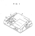
- Fig. 1 is a perspective view, partly broken away, showing an embodiment of the ink dot printer according to the invention;
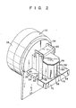
- Fig. 2 is a perspective view, enlarged in scale, showing the printing head in the ink dot printer shown in Fig. 1;
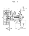
- Fig. 3 is a longitudinal sectional view schematically showing the printing head, recorded medium facing the printing head and peripheral components of the recorded medium shown in Fig. 1;
- Fig. 4 is a rear view showing a magnetic member with cores and coils, constituting an electromagnet of needle drive means for the printing head shown in Fig. 3;
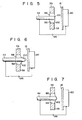
- Fig. 5 is a sectional view taken in a horizontal direction, schematically showing a needle which locates at the normal position, with the tip thereof immersed in a magnetic ink film formed in a slit between the pair of the magnetic plates of the ink film forming means, the tip of the needle noted above being in contact with the inner surface of the magnetic ink film which locates on the side of the recorded medium;
- Fig. 6 is a sectional view similar to Fig. 5, schematically showing the needle which locates at a projected position, with the tip of the needle projecting from the inner surface of the magnetic film and being closer to the recorded medium; and
- Fig. 7 is a sectional view similar to Figs. 5 and 6, but showing a needle in a modification of the ink dot printer, the needle being located at a normal position with the tip thereof slightly projecting from the inner surface of the magnetic ink film, magnetic ink being supplied to the tip surface of the tip of the needle from the magnetic ink film by the surface tension of the magnetic ink.
- Fig. 1 shows an embodiment of the ink dot printer according to the invention. The illustrated ink dot printer has a
housing 10 which accommodates acarriage shaft 12 and aguide shaft 14 that extend parallel to each other. Acarriage 16 is mounted for reciprocal movement on thecarriage shaft 12 andguide shaft 14. Aprinting head 20 facing arecording sheet 18 which serves as a recorded medium is mounted on thecarriage 16. - As clearly shown in Fig. 2, the
printing head 20 has ahead support 24 havingbolt holes 22 for receiving bolts for bolting theprinting head 20 to thecarriage 16. Ahead cover 26, made of a synthetic resin, is mounted on thehead support 24. A rearcircular portion 28 of thehead cover 26 accommodates needle drive means 30, as shown in Fig. 3. - The needle drive means 30 has a
magnetic member 34 which is made of a magnetic material and is bonded to a stepped portion of thehead cover 26, as shown in Fig. 3. Themagnetic member 34 has apartition wall 32 of a flat shape. Thepartition wall 32, as shown in Figs. 3 and 4, has a plurality ofcores 38 which are in a circular arrangement and each of which carries acoil 36 wound thereon. Themagnetic member 34 further hasyokes 40 located outside of thecores 38 in the radial direction. Thecoils 36 are energized by a printing signal provided from control means (not shown). In this embodiment, the voltage applied to thecoils 36 is from about 12 to about 13 volts. - The base portion of an
armature 42 is rotatably mounted on the eachyoke 40 so as to make thearmature 42 face thecorresponding core 38, as shown in Fig. 3. The base end of aneedle 44 is fixed to the free end portion of the eacharmature 42 through insulation means for preventing a failure of electrical insulation between theneedle 44 and thearmature 42. In this embodiment, the fixed point of the free end portion to which the base end of theneedle 44 is fixed is made of electricaly insulation material and the number of theneedle 44 is nine. Theneedle 44 is made of a nonmagnetic material having electrical conductivity, e.g., stainless steel. The diameter of theneedle 44 is approximately 0.2 mm. As shown in Fig. 3, aneedle spring 46 is wound around theneedle 44 between thepartition wall 32 of themagnetic member 34 and thearmature 42. Theneedle spring 46 urges thearmature 42, together with theneedle 44, toward the reaward of the head cover 26 (i.e., to the left in Fig. 3). The nineneedles 44 penetrate throughholes 48 formed Ïi1 a circular arrangement in thepartition wall 32 of themagnetic member 34, as shown in Fig. 4. Theseneedles 44 further penetrate an intermediate guide 50 and anfree end guide 52 provided in thehead cover 26 and the free ends of theseneedles 44 reach inkfilm forming means 54 which serves as ink supply means, as shown in Fig. 3. - The inkfilm forming means 54 includes a pair of vertically disposed
magnetic plates electro magnet 60 serving as exciting means. Theelectro magnet 60 is disposed on top of thehead cover 26 and is coupled to the rear ends of the pair ofmagnetic plates head cover 26. Thecircular portion 28 of thehead cover 26, as shown in Fig. 3, further accommodates areturn spring 62 urging thearmature 42 in the returning direction, and astop 64 which determines the return position of thearmature 42. A printedwiring board 68 is fixed to thehead cover 26. The printedwiring board 68 has an electric circuit for controlling the energization of thecoil 36, and is provided with aconnector 66. - The ink film forming means 54 further includes an
ink tank 70 made of a synthetic resin. Theink tank 70 is fixed to the underside of a front end portion of thehead cover 26. Anink impregnation member 72 is mounted in theink tank 70 andmagnetic ink 74 is stored in theink tank 70. Ahole 76 is formed at the top of theink tank 70. Lower end portions of the pair ofmagnetic plates hole 76 and immersed in themagnetic ink 74. Anink cartridge 78 for supplyingmagnetic ink 74 to theink tank 70 is removably attached on top of theink tank 70, as shown in Fig. 2. - The
housing 10 of the ink dot printer further accomodates anelectrode 80 which also functions as a platen, as shown in Fig. 3. Theelectrode 80 is supported by anelectrode holder 82 so as to make theelectrode 80 face theprinting head 20. In this embodiment, theelectrode 80 is made of copper and the surface of theelectrode 80 which is to be contacted therecording sheet 18 is provided with an insulating film of a polyimide resin. The opposite side ends of theelectrode 80 are supported by side plates (not shown) in thehousing 10 through electric insulating members (not shown). - Sheet pressing
guide rollers recording sheet 18 into closely contact with theelectrode 80 are provided above and below theelectrode 80. Asheet feed roller 88 and asheet tension roller 90 are provided above and below the sheet pressingguide rollers sheet feed roller 88 is paired with a sheetfeed pressing roller 92. Thesheet tension roller 90 is paired with asheet pressing roller 94. - A voltage of a predetermined strength is applied between the
needles 44 and theelectrode 80 from power source means 96 to produce an electric field of a predetermined field intensity. Further, in this embodiment the free end surface of the free end of eachneedle 44 is rounded, as shown in Fig. 5, to prevent discharge between it and theelectrode 80. - With the embodiment of the ink dot printer having the above construction, when the
electro magnet 60 of the ink film forming means 54 is energized, a magnetic field is produced in theslit 56 between the pair ofmagnetic plates magnetic ink 74 in theink tank 70 is withdrawn upwards along theslit 56 to form amagnetic ink film 98 having a predetermined thickness, as shown in Fig. 5. At this time, the free end surface of thefree end 100 of eachneedle 44 located in the normal position is in contact with theinner surface 102 of themagnetic ink film 98 which locates on the side of therecording sheet 18. Further, simultaneous with the energization of themagnet 60 in the ink film forming means 54, an electric field of a predetermined intensity is formed between eachneedle 44 and theelectrode 80 by the power source means 96. However, the intensity of this electric field is insufficient to cause the magnetic ink to fly from the free end surfaces of the free ends 100 of theneedles 44 toward the electrode 80 (i.e., toward the recording sheet 18) when theneedles 44 are located in the normal position. - However, when the
needle 44 is displaced to a projected position nearer therecording sheet 18, as shown in Fig. 6, a predetermined amount of magnetic ink attached to the free end surface of thefree end 100 of theneedle 44 is caused, by the electric field, to fly toward the electrode 80 (i.e., toward the recording sheet 18), because the strength 6f the electric field betwteen theneedle 44 and theelectrode 80 is increased. In consequence, an ink dot having a predetermined size is formed on therecording sheet 18. - In this embodiment, the free end surface of the
free end 100 of theneedle 44 located in the normal, i.e., non-projected, position (see Fig. 5) is in contact with theinner surface 102 of themagnetic ink film 98 which locates on the side of therecording sheet 18. Therefore, even when theneedle 44 is moved between the normal position shown in Fig. 5 and the projected position shown in Fig. 6, no great wave is produced on thesurface 102 of themagnetic ink film 98. Thus, a standard amount of magnetic ink in themagnetic ink film 98 is attached to the free end surface of thefree end 100 of theneedle 44 when theneedle 44 locates at the normal position. Moreover, even when twoadjacent needles 44 are simultaneously displaced from the normal position to the projected position, no magnetic ink will be caused to splash out from between the adjacent twoneedles 44 toward therecording sheet 18. It is thus possible to form ink dots having a constant size and density on therecording sheet 18. - it is well known from the several documents that the magnetic ink having low resistivity and good electric conductivity have difficulty in flying by a electric field. In this invention, since the
needle 44 is made of an electrically conductive material, magnetic ink which is easy in flying by a electric field (that is, have high resistivity and low electric conductivity) can be used in the ink dot printer of this invention. - The above embodiment of the invention is given for the purpose of illustrating the invention and is by no means limitative. Various changes and modifications of the above embodiment thus may be made without departing from the scope of the invention.
- For example, the free end surface of the
free end 100 of theneedle 44 may slightly projects from theinner surface 102 of themagnetic ink film 98 when theneedle 44 locates at the normal position, as shown in Fig. 7. With this arrangement, the same effects as with the above embodiment may be obtained, so long as magnetic ink is supplied to the free end surface of thefree end 100 of theneedle 44 by the surface tension in thesurface 102 of themagnetic ink film 98. - Power source means 96 may be so constructed that, as electric insulating means between the
armature 42 and theneedle 44, voltage in theneedle 44 becomes zero and voltage in theelectrode 82 becomes plus or minus. - And, as non-magnetic material having electric conductivity for the
needle 44, metal, such as tungsten, borontungsten or brass. etc., and reinforced plastic, such as CFRP (carbon fiber reinforced plastic), including electric conductive material may be used.
Claims (3)
Applications Claiming Priority (6)
| Application Number | Priority Date | Filing Date | Title |
|---|---|---|---|
| JP224384/84 | 1984-10-25 | ||
| JP22438484A JPS61102266A (en) | 1984-10-25 | 1984-10-25 | ink dot printer |
| JP233945/84 | 1984-11-06 | ||
| JP233947/84 | 1984-11-06 | ||
| JP23394784A JPS61112653A (en) | 1984-11-06 | 1984-11-06 | ink dot printer |
| JP23394584A JPS61110565A (en) | 1984-11-06 | 1984-11-06 | Ink dot printer |
Publications (2)
| Publication Number | Publication Date |
|---|---|
| EP0179457A1 EP0179457A1 (en) | 1986-04-30 |
| EP0179457B1 true EP0179457B1 (en) | 1989-01-25 |
Family
ID=27330893
Family Applications (1)
| Application Number | Title | Priority Date | Filing Date |
|---|---|---|---|
| EP85113459A Expired EP0179457B1 (en) | 1984-10-25 | 1985-10-23 | Ink dot printer |
Country Status (3)
| Country | Link |
|---|---|
| US (1) | US4749292A (en) |
| EP (1) | EP0179457B1 (en) |
| DE (1) | DE3567831D1 (en) |
Family Cites Families (16)
| Publication number | Priority date | Publication date | Assignee | Title |
|---|---|---|---|---|
| FR96354E (en) * | 1967-12-22 | 1972-06-16 | Int Standard Electric Corp | Improvements to printing machines. |
| JPS5845352B2 (en) * | 1977-06-13 | 1983-10-08 | 株式会社リコー | Recording method |
| JPS6029792B2 (en) * | 1978-07-10 | 1985-07-12 | 三菱レイヨン株式会社 | Anti-discharge printing method for fabrics made of hydrophobic fibers |
| IT1119164B (en) * | 1979-09-19 | 1986-03-03 | Olivetti & Co Spa | IMPACT PRINTING DEVICE |
| JPS57142371A (en) * | 1981-02-27 | 1982-09-03 | Tokyo Tungsten Co Ltd | Terminal for dot printer and its manufacturing method |
| JPS57159662A (en) * | 1981-03-27 | 1982-10-01 | Fujitsu Ltd | Non-impact wire dot printer |
| JPS59188449A (en) * | 1983-04-12 | 1984-10-25 | Tokyo Electric Co Ltd | ink dot printer |
| JPS59229345A (en) * | 1983-05-24 | 1984-12-22 | Fuji Xerox Co Ltd | Image recording apparatus |
| US4552469A (en) * | 1983-06-10 | 1985-11-12 | Tokyo Electric Co., Ltd. | Ink dot printer |
| JPS604074A (en) * | 1983-06-22 | 1985-01-10 | Tokyo Electric Co Ltd | dot printer |
| JPS604070A (en) * | 1983-06-22 | 1985-01-10 | Tokyo Electric Co Ltd | Dot printer |
| JPS604073A (en) * | 1983-06-22 | 1985-01-10 | Tokyo Electric Co Ltd | dot printer |
| JPS6090771A (en) * | 1983-10-26 | 1985-05-21 | Tokyo Electric Co Ltd | ink dot printer |
| JPS6092862A (en) * | 1983-10-26 | 1985-05-24 | Tokyo Electric Co Ltd | ink dot printer |
| JPS60219064A (en) * | 1984-04-14 | 1985-11-01 | Katsusato Fujiyoshi | Dot wire |
| US4696589A (en) * | 1984-10-26 | 1987-09-29 | Tokyo Electric Co., Ltd. | Ink-dot printer |
-
1985
- 1985-10-17 US US06/788,348 patent/US4749292A/en not_active Expired - Fee Related
- 1985-10-23 EP EP85113459A patent/EP0179457B1/en not_active Expired
- 1985-10-23 DE DE8585113459T patent/DE3567831D1/en not_active Expired
Also Published As
| Publication number | Publication date |
|---|---|
| DE3567831D1 (en) | 1989-03-02 |
| EP0179457A1 (en) | 1986-04-30 |
| US4749292A (en) | 1988-06-07 |
Similar Documents
| Publication | Publication Date | Title |
|---|---|---|
| US4300845A (en) | Dot matrix print head | |
| US4661002A (en) | Dot matrix printer | |
| US4749292A (en) | Ink dot printer | |
| US4603338A (en) | Ink dot printer | |
| EP0179493B1 (en) | Ink-dot printer | |
| EP0128558B1 (en) | Ink dot printer | |
| US4484519A (en) | Stylus driving apparatus for printers | |
| EP0179494B1 (en) | Ink-dot printer | |
| US3961336A (en) | Electrode print head | |
| EP0117123B1 (en) | Ink supply for a dot printer | |
| JPH028906B2 (en) | ||
| US4859095A (en) | Printing head with current passing through the print wire | |
| JPS61106267A (en) | ink dot printer | |
| JPS61112653A (en) | ink dot printer | |
| JPS61104864A (en) | ink dot printer | |
| JPS61102265A (en) | ink dot printer | |
| JPS61110565A (en) | Ink dot printer | |
| JPS61110566A (en) | ink dot printer | |
| JPS61104863A (en) | ink dot printer | |
| JPS61102266A (en) | ink dot printer | |
| JPS61102268A (en) | ink dot printer | |
| JPS61112657A (en) | ink dot printer | |
| JPS61106268A (en) | ink dot printer | |
| JPS6319156Y2 (en) | ||
| JPS61112655A (en) | Ink dot printer |
Legal Events
| Date | Code | Title | Description |
|---|---|---|---|
| PUAI | Public reference made under article 153(3) epc to a published international application that has entered the european phase |
Free format text: ORIGINAL CODE: 0009012 |
|
| AK | Designated contracting states |
Kind code of ref document: A1 Designated state(s): DE FR GB IT |
|
| 17P | Request for examination filed |
Effective date: 19860924 |
|
| 17Q | First examination report despatched |
Effective date: 19880112 |
|
| GRAA | (expected) grant |
Free format text: ORIGINAL CODE: 0009210 |
|
| AK | Designated contracting states |
Kind code of ref document: B1 Designated state(s): DE FR GB IT |
|
| REF | Corresponds to: |
Ref document number: 3567831 Country of ref document: DE Date of ref document: 19890302 |
|
| ITF | It: translation for a ep patent filed | ||
| ET | Fr: translation filed | ||
| PLBE | No opposition filed within time limit |
Free format text: ORIGINAL CODE: 0009261 |
|
| STAA | Information on the status of an ep patent application or granted ep patent |
Free format text: STATUS: NO OPPOSITION FILED WITHIN TIME LIMIT |
|
| 26N | No opposition filed | ||
| PGFP | Annual fee paid to national office [announced via postgrant information from national office to epo] |
Ref country code: FR Payment date: 19920914 Year of fee payment: 8 |
|
| PGFP | Annual fee paid to national office [announced via postgrant information from national office to epo] |
Ref country code: GB Payment date: 19921012 Year of fee payment: 8 |
|
| ITTA | It: last paid annual fee | ||
| PGFP | Annual fee paid to national office [announced via postgrant information from national office to epo] |
Ref country code: DE Payment date: 19921230 Year of fee payment: 8 |
|
| PG25 | Lapsed in a contracting state [announced via postgrant information from national office to epo] |
Ref country code: GB Effective date: 19931023 |
|
| GBPC | Gb: european patent ceased through non-payment of renewal fee |
Effective date: 19931023 |
|
| PG25 | Lapsed in a contracting state [announced via postgrant information from national office to epo] |
Ref country code: FR Effective date: 19940630 |
|
| PG25 | Lapsed in a contracting state [announced via postgrant information from national office to epo] |
Ref country code: DE Effective date: 19940701 |
|
| REG | Reference to a national code |
Ref country code: FR Ref legal event code: ST |