EP0178187B1 - Apparatus and method for continuously producing filled dough pieces - Google Patents
Apparatus and method for continuously producing filled dough pieces Download PDFInfo
- Publication number
- EP0178187B1 EP0178187B1 EP85307347A EP85307347A EP0178187B1 EP 0178187 B1 EP0178187 B1 EP 0178187B1 EP 85307347 A EP85307347 A EP 85307347A EP 85307347 A EP85307347 A EP 85307347A EP 0178187 B1 EP0178187 B1 EP 0178187B1
- Authority
- EP
- European Patent Office
- Prior art keywords
- dough
- filled
- cutters
- dividers
- teeth
- Prior art date
- Legal status (The legal status is an assumption and is not a legal conclusion. Google has not performed a legal analysis and makes no representation as to the accuracy of the status listed.)
- Expired
Links
- 238000000034 method Methods 0.000 title claims abstract description 12
- 239000000463 material Substances 0.000 claims description 11
- 230000001360 synchronised effect Effects 0.000 abstract description 2
- 239000000945 filler Substances 0.000 description 16
- 238000013459 approach Methods 0.000 description 1
- 235000008429 bread Nutrition 0.000 description 1
- 235000009508 confectionery Nutrition 0.000 description 1
- 238000004519 manufacturing process Methods 0.000 description 1
- 238000000926 separation method Methods 0.000 description 1
Images

Classifications
-
- A—HUMAN NECESSITIES
- A21—BAKING; EDIBLE DOUGHS
- A21C—MACHINES OR EQUIPMENT FOR MAKING OR PROCESSING DOUGHS; HANDLING BAKED ARTICLES MADE FROM DOUGH
- A21C11/00—Other machines for forming the dough into its final shape before cooking or baking
-
- A—HUMAN NECESSITIES
- A21—BAKING; EDIBLE DOUGHS
- A21C—MACHINES OR EQUIPMENT FOR MAKING OR PROCESSING DOUGHS; HANDLING BAKED ARTICLES MADE FROM DOUGH
- A21C9/00—Other apparatus for handling dough or dough pieces
- A21C9/06—Apparatus for filling pieces of dough such as doughnuts
-
- A—HUMAN NECESSITIES
- A21—BAKING; EDIBLE DOUGHS
- A21C—MACHINES OR EQUIPMENT FOR MAKING OR PROCESSING DOUGHS; HANDLING BAKED ARTICLES MADE FROM DOUGH
- A21C11/00—Other machines for forming the dough into its final shape before cooking or baking
- A21C11/10—Other machines for forming the dough into its final shape before cooking or baking combined with cutting apparatus
-
- A—HUMAN NECESSITIES
- A23—FOODS OR FOODSTUFFS; TREATMENT THEREOF, NOT COVERED BY OTHER CLASSES
- A23G—COCOA; COCOA PRODUCTS, e.g. CHOCOLATE; SUBSTITUTES FOR COCOA OR COCOA PRODUCTS; CONFECTIONERY; CHEWING GUM; ICE-CREAM; PREPARATION THEREOF
- A23G3/00—Sweetmeats; Confectionery; Marzipan; Coated or filled products
- A23G3/02—Apparatus specially adapted for manufacture or treatment of sweetmeats or confectionery; Accessories therefor
Definitions
- the present invention relates to an apparatus and method for continuously producing filled dough pieces from a continuously fed filled cylindrical dough body, and particularly to an apparatus and method for continuously producing separate filled dough pieces of a desired shape without exposing the filler by cutting the continuously fed filled cylindrical dough body into pieces.
- Japanese Patent Publication 1169/69 discloses a confectionery molder where oppositely positioned toothed plates, each having two converging faces to form a tooth, cut a bar-shaped filled dough h body conveyed on a conveyor belt, and then the upper toothed plates sway laterally to roll divided . dough pieces in the space surrounded by the' adjacent teeth to form spherical filler-containing dough pieces.
- this apparatus can make ball-shaped filled dough pieces, it requires a complex mechanism and the filler is liable to be exposed when the toothed plates cut the bar-shaped filler containing dough body.
- CH-A-364231 discloses a method for continuously producing filled dough pieces from a continuously fed filled cylindrical dough body, comprising constricting at regular intervals a portion of the filled cylindrical dough body, while being fed on a conveyor belt, to make a flattened portion which is almost exclusively composed of outer material, and to cut the filled cylindrical dough body into separate filled dough pieces of a desired shape.
- the same document also discloses an apparatus which enable the performance of the above method and which comprise a conveyor belt for feeding said dough body and a plurality of dividers, said dividers being disposed at predetermined intervals on the periphery of a wheel arranged to rotate about a horizontal shaft extending perpendicularly to the direction of movement of the conveyor, each divider being adapted slidably to engage the conveyor belt such that, in use, the dividers flatten the cylindrical dough body from above and cut the flattened dough body to produce separate filled dough pieces.
- an apparatus for continuously producing filled dough pieces from a continuously fed filled cylindrical dough body comprising a conveyor belt for feeding said dough body between a pair of rotary disc cutters slidably disposed on the conveyor belt, said cutters being arranged to be synchronously driven in opposite directions, each of the rotary disc cutters being formed with a plurality of teeth at predetermined intervals around its periphery, each of the teeth of a rotary disc cutter in operation periodically contacting the corresponding tooth of the other rotary disc cutter to cut the dough body fed therebetween and a plurality of dividers, said dividers being positioned above the pair of cutters and disposed at predetermined intervals on the periphery of a wheel arranged to rotate about a horizontal shaft extending perpendicularly to the direction of movement of the conveyor, each divider being adapted slidably to engage corresponding teeth of the rotary disc cutters over a certain distance such that, in use, the dividers flatten the cylindrical dough body from above, while corresponding
- the dividers each having a cutting edge, constrict the filled cylindrdical dough body cooperatively with the pair of rotary disc cutters which cut the flattened dough portion containing no filler, so that perfectly incrusted spherical dough pieces are produced without exposing the filler.
- a method of continuously producing filled dough pieces from a filled cylindrical dough body comprising constricting at regular intervals a portion of the filled cylindrical dough body, while being fed on a conveyor belt, to make a flattened portion which is almost exclusively composed of outer material, and, while maintaining the height of the flattened portion, laterally narrowing the width thereof to the cut the filled cylindrical dough body into separate filled dough pieces of a desired shape.
- Each divider constricts and flattens a portion of the filled cylindrical dough body.
- the cutting edge of the divider is preferably blunt and it presses the cylindrical dough body to flatten it till the outer layer is flattened and the filler is removed from the area.
- the dough body is then narrowed and cut from both sides by the pair of disc cutters disposed beneath the dividers.
- the dividers are preferably radially mounted on the periphery of a wheel. They periodically compress the cylindrical dough body. By changing the space between the dividers at the periphery of the wheel, for example, filled dough pieces of a different length can be produced.
- flattening the dough body by the divider and narrowing the flattened dough portion by the pair of rotary disc cutters are carried out in synchronism in such a mannerthat, when a certain divider presses the cylindrical dough body to a predetermined height, the cutters can compress, narrow, and cut the flattened dough portion which is composed almost exclusively of the outer material, thereby cutting the cylindrical dough body into separate spherical or variously shaped or dimensioned incrusted dough pieces.
- a pair of rotary disc cutters 2 and 2' are disposed slidably on a conveyor belt 4.
- the cutters have a plurality of teeth 1 and 1', as seen in Fig. 4(C), to compress, narrow, and cut the dough and are located opposite to each other and adapted to be synchronously driven in opposite directions.
- the rotation of the cutters is carried out through rotary shafts 3 and 3', bevel gears 7, 8, and 7', 8' and by rotary shafts 6 and 6'.
- the teeth are provided at predetermined intervals circumferentially of the rotary disc cutters and each tooth is arranged periodically to be in contact with a tooth from the other cutter to cut the dough at the middle of the belt 4.
- Each of the cutters 2 and 2' has upper and lower flat surfaces and a predetermined thickness, preferably slightly less than double the thickness of the outer layer 17 of the dough body 18.
- the cutters rotate at the same angular velocity to cut the dough and produce incrusted filled dough pieces in cooperation with dividers 5.
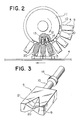
- Fig. 2 shows a plurality of dividers 5 and a wheel 11 to support the same and shows the positional relationship between the upper flat surfaces of the rotary disc cutters 2 and 2' and the flat faces 9 of the dividers 5.
- a perspective view of a divider 5 is shown in Fig. 3.
- the divider consists of a generally rectangular body.
- the outermost end surface 9 is flat and slidably engages the teeth 1 and 1' of the cutters 2 and 2' when they come into contact with each other.
- the opposite end of the divider 5 is provided with a rod 10, circular in cross-section, with a protruding ring 14.
- a recess 21 is provided across the outermost end surface 9 and the leading surface, and another recess 21 is formed across the outermost end surface and the trailing surface of the divider 5, in such a manner that the middle portion of the outermost end surface is the narrowest.
- FIG. 3 An example of the recess 21 is shown in Fig. 3. It forms a triangular indent on each of the adjoining outermost end and the leading or trailing end surfaces, and constitutes two faces of an imaginary tetrahedron. The edge between the two faces is indicated by a line 20.
- This recess is designed to accommodate the portion of the dough body protruding above the cutters 2 and 2' when the dough is fed to the cutting area.
- the shape of the recess can be changed to respond to the configuration of the desired filled dough pieces.
- the rod 10 is adapted to be loosely fitted in one of a number of holes 12 radially bored in the periphery of the wheel 11 at predetermined intervals.
- the hole 12 may be circular in cross-section and has a circular shoulder near the inward end. The diameter of the hole inside the shoulder is smaller than the remainder.
- a coil spring 13 is provided between the rod 10 and the hole 12 and is held between the shoulder of the hole 12 and the ring 14 of the rod 10:
- a stopper 15 is provided at the outer end of the hole 12 and engages the ring 14 positioned within the hole so that the rod 10 may not leave the hole 12 by the rotation of the wheel or by the pressure of the spring member 13. Therefore, the dividers 5 can be pressed in the radial direction of the wheel 11 or restored to their original positions depending on the pressure externally applied.
- the position of the wheel 11 is so arranged that the flat face 9 of the divider 5 is in contact with the teeth 1 and 1' of the cutters 2 and 2' for a distance / (shown in Fig. 4(B); also see Fig. 2), while the dividers 5 rotate around the axis of the wheel 11 in the clockwise direction in Fig. 2, as shown by a curved arrow. For the distance / the divider 5 moves in the horizontal direction.
- the bottom of the recess 20 is shown by broken lines in Fig. 2.
- the filled cylindrical dough body 18 is conveyed on the belt 4 in the direction shown by an arrow under the belt 4 in Fig. 2 and enters between the divider and the belt and simultaneously enters between the cutters.
- the rotation of the divider is so synchronized with the rotation of the cutters that then the flat face 9 of one divider 5 approaches its lowest position, the flat face 9 of the divider 5 contacts a pair of teeth 1 and 1' of the cutters 2 and 2'.
- the wheel 11 further rotates, the divider 5 is pushed in the direction of the center of the wheel 11 against the spring 13.
- the spring 13 is compressed to the greatest degree. At that time, the teeth 1 and 1' also contact each other.
- the filled cylindrical dough body 18 conveyed on the belt 4 enters between the dividers 5 and the belt 4 and between the cutters 2 and 2'.
- a divider 5 gradually compresses the dough from above, while the cutters 2 and 2' squeeze the dough from both sides.
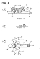
- the relationships of the movements of the dough, the cutters and the divider are illustrated in Fig. 4.
- the point at which the divider 5 comes into contact with the dough 18 is shown by the reference number (1) in Fig. 4(A).
- the cross-section of the dough is as shown in Fig. 4(B) by the reference number (1).
- the teeth 1 and 1' of the cutters 2 and 2' touch the dough.
- the separation of dough pieces from the cylindrical dough body without exposing the filler is facilitated by the mechanism where the flat face 9 of the divider 5, while rotating around the axis of the wheel 11 and in contact with the teeth 1 and 1' of the cutters 2 and 2', compresses the portion of the cylindrical dough body where it is cut over a certain distance.
- the number of dividers or teeth, their dimensions and intervals, and the speed of rotation may be changed to respond to the required dimensions of the filled dough pieces desired, the production rate, and so forth.
- the tensility of the outer material of the cylindrical dough body to be cut should be taken into consideration in working the invention. If the outer material is very tensile so that it can readily stretch and shrink, such as rice-cake dough or bread dough, the divider can compress it more than the other types of dough, so that the height of the cutters 2 and 2' can be minimal.
- a continuously fed filled cylindrical dough body is compressed from above at the portion where it is cut to the extent that the filler is almost completely excluded from the compressed area, and then cut by oppositely arranged teeth of the cutter, thereby to cut the dough into perfectly incrusted filled dough pieces of a desired shape.
Landscapes
- Life Sciences & Earth Sciences (AREA)
- Engineering & Computer Science (AREA)
- Food Science & Technology (AREA)
- Chemical & Material Sciences (AREA)
- Polymers & Plastics (AREA)
- Confectionery (AREA)
- Manufacturing And Processing Devices For Dough (AREA)
- Blow-Moulding Or Thermoforming Of Plastics Or The Like (AREA)
- Fish Paste Products (AREA)
- Containers And Plastic Fillers For Packaging (AREA)
Abstract
Description
- The present invention relates to an apparatus and method for continuously producing filled dough pieces from a continuously fed filled cylindrical dough body, and particularly to an apparatus and method for continuously producing separate filled dough pieces of a desired shape without exposing the filler by cutting the continuously fed filled cylindrical dough body into pieces.
- Japanese Patent Publication 1169/69 discloses a confectionery molder where oppositely positioned toothed plates, each having two converging faces to form a tooth, cut a bar-shaped filled dough h body conveyed on a conveyor belt, and then the upper toothed plates sway laterally to roll divided . dough pieces in the space surrounded by the' adjacent teeth to form spherical filler-containing dough pieces. Although this apparatus can make ball-shaped filled dough pieces, it requires a complex mechanism and the filler is liable to be exposed when the toothed plates cut the bar-shaped filler containing dough body.
- CH-A-364231 discloses a method for continuously producing filled dough pieces from a continuously fed filled cylindrical dough body, comprising constricting at regular intervals a portion of the filled cylindrical dough body, while being fed on a conveyor belt, to make a flattened portion which is almost exclusively composed of outer material, and to cut the filled cylindrical dough body into separate filled dough pieces of a desired shape.
- The same document also discloses an apparatus which enable the performance of the above method and which comprise a conveyor belt for feeding said dough body and a plurality of dividers, said dividers being disposed at predetermined intervals on the periphery of a wheel arranged to rotate about a horizontal shaft extending perpendicularly to the direction of movement of the conveyor, each divider being adapted slidably to engage the conveyor belt such that, in use, the dividers flatten the cylindrical dough body from above and cut the flattened dough body to produce separate filled dough pieces.
- It is an object of the present invention to provide an apparatus and method for continuously producing filled dough pieces.
- It is another object of the present invention to provide an apparatus and method for continuously cutting a filled cylindrical dough body, which is continuously conveyed, to make spherical or variously shaped dough pieces, the filler of which is completely incrusted by the outer material.
- It is a further object of the present invention to provide an apparatus and method for continuously cutting a filled cylindrical dough body, which is continuously conveyed, by which the filled cylindrical dough body is cut in a simple and reliable process to form separate spherical or variously shaped dough pieces consisting of a filler incrusted by the outer material.
- In one aspect of the present invention, an apparatus for continuously producing filled dough pieces from a continuously fed filled cylindrical dough body is provided, comprising a conveyor belt for feeding said dough body between a pair of rotary disc cutters slidably disposed on the conveyor belt, said cutters being arranged to be synchronously driven in opposite directions, each of the rotary disc cutters being formed with a plurality of teeth at predetermined intervals around its periphery, each of the teeth of a rotary disc cutter in operation periodically contacting the corresponding tooth of the other rotary disc cutter to cut the dough body fed therebetween and a plurality of dividers, said dividers being positioned above the pair of cutters and disposed at predetermined intervals on the periphery of a wheel arranged to rotate about a horizontal shaft extending perpendicularly to the direction of movement of the conveyor, each divider being adapted slidably to engage corresponding teeth of the rotary disc cutters over a certain distance such that, in use, the dividers flatten the cylindrical dough body from above, while corresponding teeth of the cutters narrow and cut the flattened dough body to produce separate filled dough pieces.
- Thus the dividers, each having a cutting edge, constrict the filled cylindrdical dough body cooperatively with the pair of rotary disc cutters which cut the flattened dough portion containing no filler, so that perfectly incrusted spherical dough pieces are produced without exposing the filler.
- In another aspect of the present invention, a method of continuously producing filled dough pieces from a filled cylindrical dough body is provided, comprising constricting at regular intervals a portion of the filled cylindrical dough body, while being fed on a conveyor belt, to make a flattened portion which is almost exclusively composed of outer material, and, while maintaining the height of the flattened portion, laterally narrowing the width thereof to the cut the filled cylindrical dough body into separate filled dough pieces of a desired shape.
- Each divider constricts and flattens a portion of the filled cylindrical dough body. The cutting edge of the divider is preferably blunt and it presses the cylindrical dough body to flatten it till the outer layer is flattened and the filler is removed from the area. The dough body is then narrowed and cut from both sides by the pair of disc cutters disposed beneath the dividers.
- The dividers are preferably radially mounted on the periphery of a wheel. They periodically compress the cylindrical dough body. By changing the space between the dividers at the periphery of the wheel, for example, filled dough pieces of a different length can be produced.
- Furthermore, flattening the dough body by the divider and narrowing the flattened dough portion by the pair of rotary disc cutters are carried out in synchronism in such a mannerthat, when a certain divider presses the cylindrical dough body to a predetermined height, the cutters can compress, narrow, and cut the flattened dough portion which is composed almost exclusively of the outer material, thereby cutting the cylindrical dough body into separate spherical or variously shaped or dimensioned incrusted dough pieces.
- An embodiment of the invention will now be described by way of example only and with reference to the accompanying drawings in which:
- Fig. 1 is a front elevational view of apparatus constructed in accordance with the present invention.
- Fig. 2 is a side elevational view, partly in cross-section, of the apparatus shown in Fig. 1.
- Fig. 3 is a perspective view of a divider of the apparatus shown in Figs. 1 and 2.
- Fig. 4(A) is a partial side elevational view corresponding to Fig. 2 showing the dividers in cross-section and illustrating the function of the dividers.
- Fig. 4(B) illustrates cross-sectional views of the cylindrical dough body at points corresponding to points (1), (2), (3), and (4) of Fig. 4(A).
- Fig. 4(C) is a plan view.of the pair of rotary disc cutters showing their function.
- In Fig. 1, a pair of
rotary disc cutters 2 and 2' are disposed slidably on aconveyor belt 4. - The cutters have a plurality of
teeth 1 and 1', as seen in Fig. 4(C), to compress, narrow, and cut the dough and are located opposite to each other and adapted to be synchronously driven in opposite directions. The rotation of the cutters is carried out throughrotary shafts 3 and 3',bevel gears rotary shafts 6 and 6'. - The teeth are provided at predetermined intervals circumferentially of the rotary disc cutters and each tooth is arranged periodically to be in contact with a tooth from the other cutter to cut the dough at the middle of the
belt 4. - Each of the
cutters 2 and 2' has upper and lower flat surfaces and a predetermined thickness, preferably slightly less than double the thickness of theouter layer 17 of thedough body 18. The cutters rotate at the same angular velocity to cut the dough and produce incrusted filled dough pieces in cooperation withdividers 5. - Fig. 2 shows a plurality of
dividers 5 and a wheel 11 to support the same and shows the positional relationship between the upper flat surfaces of therotary disc cutters 2 and 2' and theflat faces 9 of thedividers 5. A perspective view of adivider 5 is shown in Fig. 3. The divider consists of a generally rectangular body. theoutermost end surface 9 is flat and slidably engages theteeth 1 and 1' of thecutters 2 and 2' when they come into contact with each other. The opposite end of thedivider 5 is provided with arod 10, circular in cross-section, with aprotruding ring 14. Arecess 21 is provided across theoutermost end surface 9 and the leading surface, and anotherrecess 21 is formed across the outermost end surface and the trailing surface of thedivider 5, in such a manner that the middle portion of the outermost end surface is the narrowest. - An example of the
recess 21 is shown in Fig. 3. It forms a triangular indent on each of the adjoining outermost end and the leading or trailing end surfaces, and constitutes two faces of an imaginary tetrahedron. The edge between the two faces is indicated by aline 20. This recess is designed to accommodate the portion of the dough body protruding above thecutters 2 and 2' when the dough is fed to the cutting area. The shape of the recess can be changed to respond to the configuration of the desired filled dough pieces. - The
rod 10 is adapted to be loosely fitted in one of a number ofholes 12 radially bored in the periphery of the wheel 11 at predetermined intervals. Thehole 12 may be circular in cross-section and has a circular shoulder near the inward end. The diameter of the hole inside the shoulder is smaller than the remainder. Acoil spring 13 is provided between therod 10 and thehole 12 and is held between the shoulder of thehole 12 and thering 14 of the rod 10: Astopper 15 is provided at the outer end of thehole 12 and engages thering 14 positioned within the hole so that therod 10 may not leave thehole 12 by the rotation of the wheel or by the pressure of thespring member 13. Therefore, thedividers 5 can be pressed in the radial direction of the wheel 11 or restored to their original positions depending on the pressure externally applied. - The position of the wheel 11 is so arranged that the
flat face 9 of thedivider 5 is in contact with theteeth 1 and 1' of thecutters 2 and 2' for a distance / (shown in Fig. 4(B); also see Fig. 2), while thedividers 5 rotate around the axis of the wheel 11 in the clockwise direction in Fig. 2, as shown by a curved arrow. For the distance / thedivider 5 moves in the horizontal direction. The bottom of therecess 20 is shown by broken lines in Fig. 2. - The filled
cylindrical dough body 18 is conveyed on thebelt 4 in the direction shown by an arrow under thebelt 4 in Fig. 2 and enters between the divider and the belt and simultaneously enters between the cutters. The rotation of the divider is so synchronized with the rotation of the cutters that then theflat face 9 of onedivider 5 approaches its lowest position, theflat face 9 of thedivider 5 contacts a pair ofteeth 1 and 1' of thecutters 2 and 2'. When the wheel 11 further rotates, thedivider 5 is pushed in the direction of the center of the wheel 11 against thespring 13. When thedivider 5 reaches the bottom of the wheel 11, thespring 13 is compressed to the greatest degree. At that time, theteeth 1 and 1' also contact each other. - Turning now to the operation of the invention, the filled
cylindrical dough body 18 conveyed on thebelt 4 enters between thedividers 5 and thebelt 4 and between thecutters 2 and 2'. Along with the progress of thedough body 18, adivider 5 gradually compresses the dough from above, while thecutters 2 and 2' squeeze the dough from both sides. The relationships of the movements of the dough, the cutters and the divider are illustrated in Fig. 4. The point at which thedivider 5 comes into contact with thedough 18 is shown by the reference number (1) in Fig. 4(A). At this point, the cross-section of the dough is as shown in Fig. 4(B) by the reference number (1). When the divider moves to point (2), theteeth 1 and 1' of thecutters 2 and 2' touch the dough. At this point, an edge of thedivider 5 comes into contact with the upper surface of theteeth 1 and 1', and the shape of the dough in cross-section is as shown in Fig. 4(B) by the reference number (2). The filler is almost completely excluded from the area. When thedivider 5 moves a little further, the middle portion of theflat surface 9 comes into contact with theteeth 1 and 1' and the dough is pressed to the height of the teeth. At this stage, the dough has a cross-section as shown in Fig. 4(B) by the reference number (3), where no filler is present and is composed only of theouter material 17. Since the portion of the dough that is compressed by thedivider 5 is free of the filler, theteeth 1 and 1' can cut the dough without causing the filler to spill. When theflat face 9 of thedivider 5 comes to the bottom of the wheel 11, theteeth 1 and l' engage each other, and the divider is most strongly pressed against the teeth by the force of thespring 13. These positional relationships are shown by the reference number (4) in Fig. 4(A) as viewed from a side and in Fig. 4(C) as viewed from above. At this time, a portion of the cylindrical dough body is separated at its foremost end, and both the trailing half of the separated portion and the leading end of the remaining cylindrical dough body are completely covered with theouter material 17. It is evident from the above that by the next cutting cycle a second dough piece completely covered with the outer material is produced. A filleddough piece 19 as produced is shown in Fig. 4(A) and 4(C). - The separation of dough pieces from the cylindrical dough body without exposing the filler is facilitated by the mechanism where the
flat face 9 of thedivider 5, while rotating around the axis of the wheel 11 and in contact with theteeth 1 and 1' of thecutters 2 and 2', compresses the portion of the cylindrical dough body where it is cut over a certain distance. The number of dividers or teeth, their dimensions and intervals, and the speed of rotation may be changed to respond to the required dimensions of the filled dough pieces desired, the production rate, and so forth. The tensility of the outer material of the cylindrical dough body to be cut should be taken into consideration in working the invention. If the outer material is very tensile so that it can readily stretch and shrink, such as rice-cake dough or bread dough, the divider can compress it more than the other types of dough, so that the height of thecutters 2 and 2' can be minimal. - According to the present invention, a continuously fed filled cylindrical dough body is compressed from above at the portion where it is cut to the extent that the filler is almost completely excluded from the compressed area, and then cut by oppositely arranged teeth of the cutter, thereby to cut the dough into perfectly incrusted filled dough pieces of a desired shape.
- Also, no exposure of the filler is observed when constricting, flattening, and splitting the cylindrical dough body, and spherical or variously shaped filled dough pieces can be successively produced without requiring a complex mechanism.
Claims (4)
Priority Applications (1)
| Application Number | Priority Date | Filing Date | Title |
|---|---|---|---|
| AT85307347T ATE39817T1 (en) | 1984-10-12 | 1985-10-14 | DEVICE AND METHOD FOR CONTINUOUSLY MAKING FILLED Dough. |
Applications Claiming Priority (2)
| Application Number | Priority Date | Filing Date | Title |
|---|---|---|---|
| JP59214888A JPS6192536A (en) | 1984-10-12 | 1984-10-12 | Method and apparatus for cutting coating layer |
| JP214888/84 | 1984-10-12 |
Publications (3)
| Publication Number | Publication Date |
|---|---|
| EP0178187A2 EP0178187A2 (en) | 1986-04-16 |
| EP0178187A3 EP0178187A3 (en) | 1986-08-27 |
| EP0178187B1 true EP0178187B1 (en) | 1989-01-11 |
Family
ID=16663225
Family Applications (1)
| Application Number | Title | Priority Date | Filing Date |
|---|---|---|---|
| EP85307347A Expired EP0178187B1 (en) | 1984-10-12 | 1985-10-14 | Apparatus and method for continuously producing filled dough pieces |
Country Status (11)
| Country | Link |
|---|---|
| US (1) | US4671759A (en) |
| EP (1) | EP0178187B1 (en) |
| JP (1) | JPS6192536A (en) |
| KR (1) | KR890004705B1 (en) |
| CN (1) | CN85107925B (en) |
| AT (1) | ATE39817T1 (en) |
| AU (1) | AU557768B2 (en) |
| CA (1) | CA1234317A (en) |
| DD (1) | DD239517A5 (en) |
| DE (1) | DE3567360D1 (en) |
| ES (1) | ES8608809A1 (en) |
Families Citing this family (21)
| Publication number | Priority date | Publication date | Assignee | Title |
|---|---|---|---|---|
| JPS62278933A (en) * | 1986-05-26 | 1987-12-03 | レオン自動機株式会社 | Cover skin cutter |
| JPS62278934A (en) * | 1986-05-26 | 1987-12-03 | レオン自動機株式会社 | Cover skin cutter |
| US4941402A (en) * | 1989-05-24 | 1990-07-17 | Alterio Joseph C D | Apparatus for encapsulating filler with dough |
| US5695797A (en) * | 1993-10-08 | 1997-12-09 | Nestec S.A. | Coextruded pet food product |
| EA000154B1 (en) * | 1995-04-19 | 1998-10-29 | Уиллетт Версатил Еквипмент Пти, Лтд. | Improved dough divider |
| CH691104A5 (en) * | 1995-09-29 | 2001-04-30 | Soremartec Sa | Device for the metered dispensing of products arrays. |
| US5755152A (en) * | 1996-12-19 | 1998-05-26 | Hunt-Wesson, Inc. | Popcorn cake machine |
| US6902754B1 (en) * | 1999-02-01 | 2005-06-07 | The Pillsbury Company | Blunt edge dough cutter |
| GB2386338A (en) * | 2002-03-14 | 2003-09-17 | Kwok Kuen So | Pastry cutter |
| US20050034581A1 (en) * | 2003-08-12 | 2005-02-17 | Eugenio Bortone | Method and apparatus for cutting a curly puff extrudate |
| EP2028948A2 (en) * | 2006-05-01 | 2009-03-04 | Wm. Wrigley Jr. Company | Apparatus and method for producing center-filled confectionery products |
| US8622729B2 (en) | 2008-12-23 | 2014-01-07 | General Mills, Inc. | Dough cutting and stamping apparatus and method |
| US8622730B2 (en) | 2008-12-23 | 2014-01-07 | General Mills, Inc. | Dough forming and cutting apparatus and method |
| USD630040S1 (en) | 2009-02-23 | 2011-01-04 | General Mills, Inc. | Kaiser roll cutter mold |
| CN101822301B (en) * | 2010-05-14 | 2012-05-23 | 福建南海食品有限公司 | Preserved fruit blancher |
| JP6008508B2 (en) | 2011-07-26 | 2016-10-19 | レオン自動機株式会社 | Method and apparatus for manufacturing encapsulated food |
| US8956138B2 (en) * | 2012-07-13 | 2015-02-17 | Progressive International Corporation | Cookie decorating tool |
| AU2016397560A1 (en) | 2016-03-14 | 2018-05-31 | General Mills, Inc. | Method and apparatus for crimping and cutting pouched dough products |
| CN106614880B (en) * | 2016-12-08 | 2022-03-04 | 中山职业技术学院 | Automatic bread pressing molding equipment |
| US11013238B2 (en) | 2018-05-24 | 2021-05-25 | General Mills, Inc. | Rotary dough cutter and method of operation |
| CN112042698B (en) * | 2020-08-31 | 2022-07-01 | 南京灵雀智能制造有限公司 | Cake cutting and forming device |
Citations (1)
| Publication number | Priority date | Publication date | Assignee | Title |
|---|---|---|---|---|
| CH364231A (en) * | 1959-01-02 | 1962-09-15 | Burkhardt Paul | Method and device for the continuous production of ravioli and similar dumplings |
Family Cites Families (5)
| Publication number | Priority date | Publication date | Assignee | Title |
|---|---|---|---|---|
| US3759650A (en) * | 1970-08-20 | 1973-09-18 | Nabisco Inc | Apparatus for processing a strip of pliable material |
| US3880030A (en) * | 1974-07-01 | 1975-04-29 | Nabisco Inc | Rotary cutter assembly |
| US4120627A (en) * | 1977-03-16 | 1978-10-17 | Eiwa Confectionary Co. | Apparatus for making ball-shaped marshmallow products |
| US4528900A (en) * | 1983-10-11 | 1985-07-16 | Nabisco Brands, Inc. | High production apparatus for forming filled edible products |
| US4574690A (en) * | 1984-07-13 | 1986-03-11 | Chiao Tsu T | Apparatus for forming wrapped food products |
-
1984
- 1984-10-12 JP JP59214888A patent/JPS6192536A/en active Pending
-
1985
- 1985-10-09 AU AU48413/85A patent/AU557768B2/en not_active Ceased
- 1985-10-10 DD DD85281612A patent/DD239517A5/en not_active IP Right Cessation
- 1985-10-11 CA CA000492854A patent/CA1234317A/en not_active Expired
- 1985-10-11 CN CN85107925A patent/CN85107925B/en not_active Expired
- 1985-10-11 ES ES547803A patent/ES8608809A1/en not_active Expired
- 1985-10-12 KR KR1019850007509A patent/KR890004705B1/en not_active Expired
- 1985-10-14 AT AT85307347T patent/ATE39817T1/en not_active IP Right Cessation
- 1985-10-14 EP EP85307347A patent/EP0178187B1/en not_active Expired
- 1985-10-14 DE DE8585307347T patent/DE3567360D1/en not_active Expired
- 1985-10-15 US US06/787,618 patent/US4671759A/en not_active Expired - Fee Related
Patent Citations (1)
| Publication number | Priority date | Publication date | Assignee | Title |
|---|---|---|---|---|
| CH364231A (en) * | 1959-01-02 | 1962-09-15 | Burkhardt Paul | Method and device for the continuous production of ravioli and similar dumplings |
Also Published As
| Publication number | Publication date |
|---|---|
| AU557768B2 (en) | 1987-01-08 |
| ES547803A0 (en) | 1986-09-01 |
| US4671759A (en) | 1987-06-09 |
| DD239517A5 (en) | 1986-10-01 |
| ES8608809A1 (en) | 1986-09-01 |
| AU4841385A (en) | 1986-04-17 |
| KR860002964A (en) | 1986-05-19 |
| CN85107925B (en) | 1988-04-13 |
| ATE39817T1 (en) | 1989-01-15 |
| JPS6192536A (en) | 1986-05-10 |
| CN85107925A (en) | 1986-04-10 |
| EP0178187A3 (en) | 1986-08-27 |
| DE3567360D1 (en) | 1989-02-16 |
| EP0178187A2 (en) | 1986-04-16 |
| CA1234317A (en) | 1988-03-22 |
| KR890004705B1 (en) | 1989-11-25 |
Similar Documents
| Publication | Publication Date | Title |
|---|---|---|
| US4671759A (en) | Apparatus for continuously producing filled dough pieces | |
| US6155814A (en) | Apparatus for continuously and uniformly supplying dough | |
| US4276800A (en) | Rotary cutter for scoring dough sheets | |
| EP0359393B1 (en) | Apparatus for the formation of a shaped food product | |
| US4692109A (en) | Apparatus for cutting filled cylindrical dough body | |
| EP0832562A2 (en) | Apparatus for cutting and shaping a spherical body | |
| US4941402A (en) | Apparatus for encapsulating filler with dough | |
| US7316556B2 (en) | Apparatus for cutting dough with nested pattern cutters | |
| PT98111B (en) | MACHINE AND PROCESS FOR AUTOMATICALLY FORMING FLOUR PASTA BASED PRODUCTS | |
| DE602005005806T2 (en) | ROTATION UNIT FOR ULTRASONIC SEALING OF TUBULAR ENDLESS BELTS | |
| US5518391A (en) | Apparatus and polyhedral member for cutting and shaping a bar-shaped dough body | |
| JPH0670669A (en) | Bread dough piece arranging method and device | |
| US4381697A (en) | Apparatus to make cookies | |
| CA1206054A (en) | Apparatus for making grooves in cigarette filters | |
| US4717328A (en) | Slitter-corrugator apparatus for pasta | |
| EP0452906B1 (en) | Apparatus for alternately arranging the direction of an article | |
| EP1256279B1 (en) | Line for processing rolled-up food products, particularly for producing croissants | |
| JPH11206330A (en) | Food molding equipment | |
| US4349574A (en) | Method and apparatus to make cookies | |
| EP0118264A1 (en) | Method for continuously manufacturing a multi-layered dough material | |
| EP0005570A1 (en) | Method and apparatus for forming a layer of emulsion-like material in a predetermined thickness and use of such an apparatus in a method and system for making cracker paste or puff paste | |
| US20050220954A1 (en) | Process and system for making shaped snack products | |
| JP2799941B2 (en) | Polyhedron for split forming of bar-shaped dough and split forming apparatus | |
| AU689412B1 (en) | Apparatus for cutting and shaping a spherical body | |
| GB1573063A (en) | Circular saw blades |
Legal Events
| Date | Code | Title | Description |
|---|---|---|---|
| PUAI | Public reference made under article 153(3) epc to a published international application that has entered the european phase |
Free format text: ORIGINAL CODE: 0009012 |
|
| AK | Designated contracting states |
Kind code of ref document: A2 Designated state(s): AT BE CH DE FR GB IT LI NL SE |
|
| PUAL | Search report despatched |
Free format text: ORIGINAL CODE: 0009013 |
|
| AK | Designated contracting states |
Kind code of ref document: A3 Designated state(s): AT BE CH DE FR GB IT LI NL SE |
|
| 17P | Request for examination filed |
Effective date: 19861018 |
|
| 17Q | First examination report despatched |
Effective date: 19871211 |
|
| ITF | It: translation for a ep patent filed | ||
| GRAA | (expected) grant |
Free format text: ORIGINAL CODE: 0009210 |
|
| AK | Designated contracting states |
Kind code of ref document: B1 Designated state(s): AT BE CH DE FR GB IT LI NL SE |
|
| REF | Corresponds to: |
Ref document number: 39817 Country of ref document: AT Date of ref document: 19890115 Kind code of ref document: T |
|
| REF | Corresponds to: |
Ref document number: 3567360 Country of ref document: DE Date of ref document: 19890216 |
|
| ET | Fr: translation filed | ||
| PLBE | No opposition filed within time limit |
Free format text: ORIGINAL CODE: 0009261 |
|
| STAA | Information on the status of an ep patent application or granted ep patent |
Free format text: STATUS: NO OPPOSITION FILED WITHIN TIME LIMIT |
|
| 26N | No opposition filed | ||
| PGFP | Annual fee paid to national office [announced via postgrant information from national office to epo] |
Ref country code: CH Payment date: 19901008 Year of fee payment: 6 |
|
| PGFP | Annual fee paid to national office [announced via postgrant information from national office to epo] |
Ref country code: SE Payment date: 19901011 Year of fee payment: 6 |
|
| PGFP | Annual fee paid to national office [announced via postgrant information from national office to epo] |
Ref country code: GB Payment date: 19901012 Year of fee payment: 6 |
|
| PGFP | Annual fee paid to national office [announced via postgrant information from national office to epo] |
Ref country code: BE Payment date: 19901018 Year of fee payment: 6 |
|
| PGFP | Annual fee paid to national office [announced via postgrant information from national office to epo] |
Ref country code: AT Payment date: 19901023 Year of fee payment: 6 |
|
| ITTA | It: last paid annual fee | ||
| PGFP | Annual fee paid to national office [announced via postgrant information from national office to epo] |
Ref country code: NL Payment date: 19901031 Year of fee payment: 6 Ref country code: FR Payment date: 19901031 Year of fee payment: 6 |
|
| PGFP | Annual fee paid to national office [announced via postgrant information from national office to epo] |
Ref country code: DE Payment date: 19901129 Year of fee payment: 6 |
|
| PG25 | Lapsed in a contracting state [announced via postgrant information from national office to epo] |
Ref country code: GB Effective date: 19911014 Ref country code: AT Effective date: 19911014 |
|
| PG25 | Lapsed in a contracting state [announced via postgrant information from national office to epo] |
Ref country code: SE Effective date: 19911015 |
|
| PG25 | Lapsed in a contracting state [announced via postgrant information from national office to epo] |
Ref country code: LI Effective date: 19911031 Ref country code: CH Effective date: 19911031 Ref country code: BE Effective date: 19911031 |
|
| BERE | Be: lapsed |
Owner name: RHEON AUTOMATIC MACHINERY CO. LTD Effective date: 19911031 |
|
| PG25 | Lapsed in a contracting state [announced via postgrant information from national office to epo] |
Ref country code: NL Effective date: 19920501 |
|
| GBPC | Gb: european patent ceased through non-payment of renewal fee | ||
| NLV4 | Nl: lapsed or anulled due to non-payment of the annual fee | ||
| PG25 | Lapsed in a contracting state [announced via postgrant information from national office to epo] |
Ref country code: FR Effective date: 19920630 |
|
| REG | Reference to a national code |
Ref country code: CH Ref legal event code: PL |
|
| PG25 | Lapsed in a contracting state [announced via postgrant information from national office to epo] |
Ref country code: DE Effective date: 19920701 |
|
| REG | Reference to a national code |
Ref country code: FR Ref legal event code: ST |
|
| EUG | Se: european patent has lapsed |
Ref document number: 85307347.6 Effective date: 19920510 |