EP0178015B1 - Semi-active night observation system with intensification of light - Google Patents
Semi-active night observation system with intensification of light Download PDFInfo
- Publication number
- EP0178015B1 EP0178015B1 EP85201573A EP85201573A EP0178015B1 EP 0178015 B1 EP0178015 B1 EP 0178015B1 EP 85201573 A EP85201573 A EP 85201573A EP 85201573 A EP85201573 A EP 85201573A EP 0178015 B1 EP0178015 B1 EP 0178015B1
- Authority
- EP
- European Patent Office
- Prior art keywords
- flash
- image
- light
- scene
- night
- Prior art date
- Legal status (The legal status is an assumption and is not a legal conclusion. Google has not performed a legal analysis and makes no representation as to the accuracy of the status listed.)
- Expired
Links
Images
Classifications
-
- G—PHYSICS
- G02—OPTICS
- G02B—OPTICAL ELEMENTS, SYSTEMS OR APPARATUS
- G02B23/00—Telescopes, e.g. binoculars; Periscopes; Instruments for viewing the inside of hollow bodies; Viewfinders; Optical aiming or sighting devices
- G02B23/12—Telescopes, e.g. binoculars; Periscopes; Instruments for viewing the inside of hollow bodies; Viewfinders; Optical aiming or sighting devices with means for image conversion or intensification
Definitions
- the invention relates to a light-intensifying semi-active night observation system comprising for normal observation of the landscape in passive operating mode a large aperture objective forming the image of the landscape on an intensifier tube, said image being transmitted.
- a television camera connected to a display device by a control unit, the activation of which allows the passage to an active operating mode by triggering the emission of a single light flash of wavelength outside the visible spectrum to produce pulsed lighting of the central area of the landscape.
- Said light flash having a very short duration and a low energy not allowing its direct exploitation to the eye, and an image memory loaded by the image of the illuminated field then read and visualized by said display device, the mode of operation consecutive to the extinction of the flash becoming passive as long as said image stored in memory is viewed, the action on said control unit allowing the return to normal observation of the landscape in passive operating mode.
- Fully passive night light intensification observation systems are known, such as observation glasses or binoculars using intensifier tubes (in the case of light devices) or television cameras with low light levels (in the case of devices heavier).
- Passive systems have the advantage of being undetectable, but their recognition range is poor when the illumination of the night sky is poor.
- U.S. Patent No. 3,509,344 discloses a night vision goggle device which combines the passive system with an active system in which the image of the scene illuminated by infrared radiation is transformed into an image visible in the telescope by means of a converter tube.
- the semi-active system object of the present invention also combining the two systems aims to very significantly improve the range of recognition while having a low detectability comparable to that of a laser rangefinder.
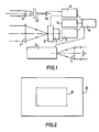
- FIG. 1 shows the diagram of the apparatus according to the invention.
- FIG. 2 represents the field of the system in passive operation and in semi-active operation.
- a large aperture objective 1 forms the image of the landscape on an intensifier tube 2.
- the objective and tube assembly operates in the visible and near infrared regions.
- This image is taken by a television camera 3 and its power supply 4 connected to a display device 5 via a control unit 6.
- the image is observed through an eyepiece 7.
- the part of the device thus described relates to its normal use in passive operation for which the system is equivalent to a television camera with low light level.
- This auxiliary lighting improves the signal / noise ratio and the contrast of the image, but the very short duration of the flash does not allow it to be used directly by the eye.
- the image is therefore stored in memory in accordance with the invention in an image memory 9 and then re-read and displayed by the display device 5.
- the operation is active for the very short duration of the flash and becomes passive during the rest the observation time of the stored image as long as the trigger is pressed, hence the term semi-active used to characterize this observation system.
- the source of the flash 10 is a laser diode providing in the near infrared pulses of the order of microseconds.
- the adjustment box 8 synchronizes the supply of the intensifier tube 2 with the emission of the flash 10 and fixes their time shift in order to produce a tomoscopy effect which makes it possible to overcome the backscattering of the atmospheric mist of the wafer atmosphere close to the observer.
- the flash emits across the spectrum a pulse of the order of ten milliseconds and not exceeding 20 milliseconds. It is then necessary to interpose an infrared filter 12 between the flash 10 and the projector 11. This pulse duration which cannot be exploited by the eye and which always requires the image to be stored in accordance with the invention is however too high for that we can introduce a tomoscopy effect.
- the intensifier tube 2 is then continuously supplied and the action on the control unit 6 only triggers the emission of the light flash.
- the tube 2 is a second or third generation microchannel tube with double proximity focusing coupled to a matrix of CCD detectors; viewer 5 is a cathode ray tube or liquid crystal micromonitor for example; the solid CCD camera 3 has a matrix of 200 x 300 points; the image memory 9 has 128 x 128 dots.
- the assembly constitutes a television camera with tomoscopy effect of small dimensions and portable by hand.
- the field in semi-active operation is represented by the rectangle B. It is the field corresponding to the image memory.
- the field illuminated by the projector 11 is slightly greater than the field B.
Description
L'invention concerne un système d'observation nocturne semi-actif à intensification de lumière comportant pour l'observation normale du paysage en mode de fonctionnement passif un objectif à grande ouverture formant l'image du paysage sur un tube intensificateur, ladite image étant transmise à une caméra de télévision reliée à un dispositif de visualisation par un boîtier de commande dont la mise en action permet le passage à un mode de fonctionnement actif en déclenchant l'émission d'un flash lumineux unique de longueur d'onde extérieure au spectre visible pour produire un éclairage pulsé de la zone centrale du paysage. Ledit flash lumineux ayant une durée très brève et une faible énergie ne permettant pas son exploitation directe à l'oeil, et une mémoire d'image chargée par l'image du champ éclairé puis relue et visualisée par ledit dispositif de visualisation, le mode de fonctionnement consécutif à l'extinction du flash devenant passif tant que ladite image mise en mémoire est visualisée, l'action sur ledit boîtier de commande permettant le retour à l'observation normale du paysage en mode de fonctionnement passif.The invention relates to a light-intensifying semi-active night observation system comprising for normal observation of the landscape in passive operating mode a large aperture objective forming the image of the landscape on an intensifier tube, said image being transmitted. to a television camera connected to a display device by a control unit, the activation of which allows the passage to an active operating mode by triggering the emission of a single light flash of wavelength outside the visible spectrum to produce pulsed lighting of the central area of the landscape. Said light flash having a very short duration and a low energy not allowing its direct exploitation to the eye, and an image memory loaded by the image of the illuminated field then read and visualized by said display device, the mode of operation consecutive to the extinction of the flash becoming passive as long as said image stored in memory is viewed, the action on said control unit allowing the return to normal observation of the landscape in passive operating mode.
On connaît des systèmes d'observation nocturne entièrement passifs à intensification de lumière comme par exemple des lunettes ou des jumelles d'observation utilisant des tubes intensificateurs (cas des appareils légers) ou encore des caméras de télévision à bas niveau de lumière (cas des appareils plus lourds).Fully passive night light intensification observation systems are known, such as observation glasses or binoculars using intensifier tubes (in the case of light devices) or television cameras with low light levels (in the case of devices heavier).
On connaît d'autre part des systèmes d'observation nocturne actifs pour lesquels une source lumineuse fournit un éclairage d'appoint du paysage. Parmi ceux-ci, les uns ont un éclairage permanent pendant la période d'observation, les autres ont un éclairage pulsé synchronisé avec un obturateur sur la voie intensificatrice (appareils de tomoscopie, US-A-3 467 773).On the other hand, active night observation systems are known for which a light source provides additional lighting for the landscape. Among these, some have permanent lighting during the observation period, the others have pulsed lighting synchronized with a shutter on the intensifying channel (tomoscopy devices, US-A-3,467,773).
Les systèmes passifs ont l'avantage d'être indé- tectables mais leur portée de reconnaissance est médiocre lorsque l'éclairement du ciel nocturne est faible.Passive systems have the advantage of being undetectable, but their recognition range is poor when the illumination of the night sky is poor.
Les systèmes actifs ont de très bonnes portées, mais ils sont très détectables par l'adversaire.Active systems have very good ranges, but they are very detectable by the opponent.
Le brevet des Etats-Unis d'Amérique n° 3509344 décrit un dispositif à lunette d'observation nocturne qui combine le système passif avec un système actif dans lequel l'image de la scène éclairée par le rayonnement infra-rouge est transformée en une image visible dans la lunette au moyen d'un tube convertisseur.U.S. Patent No. 3,509,344 discloses a night vision goggle device which combines the passive system with an active system in which the image of the scene illuminated by infrared radiation is transformed into an image visible in the telescope by means of a converter tube.
Le système semi-actif objet de la présente invention combinant également les deux systèmes a pour but d'améliorer très sensiblement la portée de reconnaissance tout en ayant une faible détectabilité comparable à celle d'un télémètre laser.The semi-active system object of the present invention also combining the two systems aims to very significantly improve the range of recognition while having a low detectability comparable to that of a laser rangefinder.
La description suivante en regard des dessins annexés, le tout donné à titre d'exemple fera bien comprendre comment l'invention peut être réalisée.The following description with reference to the appended drawings, all given by way of example will make it clear how the invention can be implemented.
La figure 1 représente le schéma de l'appareil conforme à l'invention.Figure 1 shows the diagram of the apparatus according to the invention.
La figure 2 représente le champ du système en fonctionnement passif et en fonctionnement semi-actif.FIG. 2 represents the field of the system in passive operation and in semi-active operation.
Sur le schéma de la figure 1, un objectif à grande ouverture 1 forme l'image du paysage sur un tube intensificateur 2. L'ensemble objectif et tube fonctionne dans le visible et le proche infra-rouge. Cette image est reprise par une caméra de télévision 3 et son alimentation 4 reliées à un dispositif de visualisation 5 par l'intermédiaire d'un boîtier de commande 6. L'image est observée à travers un oculaire 7.In the diagram in FIG. 1, a large aperture objective 1 forms the image of the landscape on an intensifier tube 2. The objective and tube assembly operates in the visible and near infrared regions. This image is taken by a television camera 3 and its power supply 4 connected to a display device 5 via a control unit 6. The image is observed through an eyepiece 7.
La partie de l'appareil ainsi décrite concerne son utilisation normale en fonctionnement passif pour lequel le système est équivalent à une caméra de télévision à bas niveau de lumière.The part of the device thus described relates to its normal use in passive operation for which the system is equivalent to a television camera with low light level.
Lorsque l'observateur a cru apercevoir une cible qu'il désire identifier, il appuie sur la gachette du boîtier de commande 6 pour déclencher, par l'intermédiaire d'un boîtier de réglage 8, l'émission d'un flash lumineux unique 10 de très courte durée et de faible énergie dont le champ est nettement délimité au moyen du projecteur 11, de façon à n'éclairer que le centre du champ observé.When the observer believes he has seen a target he wishes to identify, he presses the trigger on the control unit 6 to trigger, via an adjustment unit 8, the emission of a
Cet éclairage d'appoint améliore le rapport signal/ bruit et le contraste de l'image, mais la durée très brève du flash n'en permet pas l'exploitation directe à l'oeil. Aussi l'image est-elle mise en mémoire conformément à l'invention dans une mémoire d'image 9 puis relue et visualisée par le dispositif de visualisation 5. Le fonctionnement est actif pendant la durée très brève du flash et devient passif pendant le reste du temps d'observation de l'image mémorisée tant que la gachette est enfoncée, d'où le terme semi-actif utilisé pour caractériser ce système d'observation.This auxiliary lighting improves the signal / noise ratio and the contrast of the image, but the very short duration of the flash does not allow it to be used directly by the eye. The image is therefore stored in memory in accordance with the invention in an
Dès que la gachette est relâchée, l'image mémorisée n'est plus visible et l'on revient au mode d'observation normal du paysage toujours en fonctionnement passif.As soon as the trigger is released, the stored image is no longer visible and we return to the normal landscape observation mode, still in passive operation.
Dans une première variante du système, la source du flash 10 est une diode laser fournissant dans le proche infra-rouge des impulsions de l'ordre de la microseconde. Le boîtier de réglage 8 synchronise l'alimentation du tube intensificateur 2 avec l'émission du flash 10 et fixe leur décalage dans le temps afin de produire un effet de tomoscopie qui permet de s'affranchir de la rétrodiffusion de la brume atmosphérique de la tranche d'atmosphère proche de l'observateur.In a first variant of the system, the source of the
Dans une seconde variante, le flash émet dans toute la gamme du spectre une impulsion de l'ordre de la dizaine de milliseconde et ne dépassant pas 20 millisecondes. Il faut alors interposer un filtre infra-rouge 12 entre le flash 10 et le projecteur 11. Cette durée d'impulsion inexploitable à l'oeil et nécessitant toujours la mise en mémoire de l'image conformément à l'invention est cependant trop élevée pour que l'on puisse introduire un effet de tomoscopie. Le tube intensificateur 2 est alors alimenté en permanence et l'action sur le boîtier de commande 6 déclenche uniquement l'émission du flash lumineux.In a second variant, the flash emits across the spectrum a pulse of the order of ten milliseconds and not exceeding 20 milliseconds. It is then necessary to interpose an
Dans un arrangement préférentiel conforme à la première variante du système, le tube 2 est un tube à microcanaux de deuxième ou de troisième génération à double focalisation de proximité couplé à une matrice de détecteurs à CCD; le visualisateur 5 est un micromoniteur à tube cathodique ou à cristaux liquides par exemple; la caméra solide 3 à CCD a une matrice de 200 x 300 points; la mémoire d'image 9 a 128 x 128 points. L'ensemble constitue une caméra de télévision à effet de tomoscopie de faibles dimensions et portable à la main.In a preferred arrangement in accordance with the first variant of the system, the tube 2 is a second or third generation microchannel tube with double proximity focusing coupled to a matrix of CCD detectors; viewer 5 is a cathode ray tube or liquid crystal micromonitor for example; the solid CCD camera 3 has a matrix of 200 x 300 points; the
Sur la figure 2, le champ du système en fonctionnement passif est représenté par le rectangle A.In FIG. 2, the field of the system in passive operation is represented by the rectangle A.
Le champ en fonctionnement semi-actif est représenté par le rectangle B. C'est le champ correspondant à la mémoire d'image. Le champ éclairé par le projecteur 11 est légèrement supérieur au champ B.The field in semi-active operation is represented by the rectangle B. It is the field corresponding to the image memory. The field illuminated by the projector 11 is slightly greater than the field B.
Claims (5)
Applications Claiming Priority (2)
| Application Number | Priority Date | Filing Date | Title |
|---|---|---|---|
| FR8415309A FR2571506B1 (en) | 1984-10-05 | 1984-10-05 | SEMI-ACTIVE NIGHT OBSERVATION SYSTEM WITH LIGHT INTENSIFICATION |
| FR8415309 | 1984-10-05 |
Publications (2)
| Publication Number | Publication Date |
|---|---|
| EP0178015A1 EP0178015A1 (en) | 1986-04-16 |
| EP0178015B1 true EP0178015B1 (en) | 1988-05-11 |
Family
ID=9308375
Family Applications (1)
| Application Number | Title | Priority Date | Filing Date |
|---|---|---|---|
| EP85201573A Expired EP0178015B1 (en) | 1984-10-05 | 1985-10-01 | Semi-active night observation system with intensification of light |
Country Status (4)
| Country | Link |
|---|---|
| US (1) | US4642452A (en) |
| EP (1) | EP0178015B1 (en) |
| DE (1) | DE3562680D1 (en) |
| FR (1) | FR2571506B1 (en) |
Families Citing this family (23)
| Publication number | Priority date | Publication date | Assignee | Title |
|---|---|---|---|---|
| GB2212689B (en) * | 1987-11-17 | 1992-01-02 | Ferranti Plc | Television camera system |
| US5113177A (en) * | 1988-10-04 | 1992-05-12 | Allied-Signal Inc. | Apparatus for a display system |
| DE4015401C1 (en) * | 1990-05-14 | 1991-11-14 | Hella Kg Hueck & Co, 4780 Lippstadt, De | |
| DE4015402A1 (en) * | 1990-05-14 | 1991-11-21 | Hella Kg Hueck & Co | LIGHTNING FLASH WARNING SYSTEM |
| GB9018174D0 (en) * | 1990-08-17 | 1990-10-03 | Pearpoint Ltd | Apparatus for reading vehicle number-plates |
| FR2706635B1 (en) * | 1993-06-11 | 1995-07-21 | Eprest | Night vision binoculars with electronic imagery. |
| US5396069A (en) * | 1993-07-01 | 1995-03-07 | The United States Of America As Represented By The Secretary Of The Air Force | Portable monocular night vision apparatus |
| US5383200A (en) * | 1993-12-20 | 1995-01-17 | Alliedsignal Inc. | Eye safe laser imaging system |
| US5519209A (en) * | 1994-06-15 | 1996-05-21 | Alliedsignal Inc. | High range resolution active imaging system using a high speed shutter and a light pulse having a sharp edge |
| US7202776B2 (en) * | 1997-10-22 | 2007-04-10 | Intelligent Technologies International, Inc. | Method and system for detecting objects external to a vehicle |
| FR2740227B1 (en) * | 1995-10-20 | 1997-11-07 | Thomson Csf | LASER TOMOSCOPIC DETECTION DEVICE |
| FR2741722B1 (en) * | 1995-11-29 | 1998-02-13 | Sfim Ind | METHOD AND DEVICE FOR ACTIVE IDENTIFICATION OF A NIGHT TARGET |
| US6416960B1 (en) | 1996-08-08 | 2002-07-09 | Prolume, Ltd. | Detection and visualization of neoplastic tissues and other tissues |
| NZ335453A (en) | 1996-12-12 | 2001-07-27 | Prolume Ltd | Microelectronic device with microlocations including photodetector for detecting bioluminescence |
| FR2775534B1 (en) * | 1998-02-27 | 2000-09-15 | D Aviat Latecoere Soc Ind | DEVICE FOR MONITORING AN ENCLOSURE, ESPECIALLY THE HOLD OF AN AIRCRAFT |
| US6529132B2 (en) | 1998-02-27 | 2003-03-04 | Societe Industrielle D'avation Latecoere | Device for monitoring an enclosure, in particular the hold of an aircraft |
| US7581852B2 (en) * | 1999-11-15 | 2009-09-01 | Xenonics, Inc. | Portable device for viewing and imaging |
| ITWX20020005A1 (en) * | 2001-05-10 | 2002-11-11 | Bae Systems Plc | REFINEMENTS IN OR RELATED TO DETECTION SYSTEMS OPERATING IN THE PRESENCE OF LASER A AND PULSES |
| US7280674B2 (en) * | 2001-06-05 | 2007-10-09 | University Of Florida Research Foundation | Device and method for object illumination and imaging using time slot allocation based upon road changes |
| US7045783B2 (en) * | 2001-06-05 | 2006-05-16 | University Of Florida Research Foundation, Inc. | Device and method for object illumination and imaging using light pulses |
| US20030193980A1 (en) * | 2001-06-05 | 2003-10-16 | Oleg Matveev | Device and method for invisible road illumination and imaging using preliminary pulses |
| US7173237B2 (en) * | 2004-10-22 | 2007-02-06 | Xenonics, Inc. | Ruggedized digital low-light viewing device |
| ITPR20040056A1 (en) * | 2004-08-04 | 2004-11-04 | Procomac Spa | PROCEDURE FOR ASSESSING THE SEALING OF A CONTAINER. |
Family Cites Families (11)
| Publication number | Priority date | Publication date | Assignee | Title |
|---|---|---|---|---|
| US3305633A (en) * | 1963-06-26 | 1967-02-21 | Gen Electric | Laser optical system |
| DE1210360B (en) * | 1964-11-07 | 1966-02-03 | Leitz Ernst Gmbh | Sighting device coupled to a laser range finder |
| GB1132505A (en) * | 1965-05-24 | 1968-11-06 | Ericsson Telefon Ab L M | Distance meter |
| NL6606802A (en) * | 1966-05-18 | 1967-11-20 | ||
| US3467773A (en) * | 1966-11-07 | 1969-09-16 | Us Navy | Television monitoring system for penetrating a light backscattering medium |
| DE1673905A1 (en) * | 1968-02-15 | 1971-09-30 | Eltro Gmbh | Optical aiming or observation device combined with a laser range finder |
| US3698812A (en) * | 1969-08-11 | 1972-10-17 | Hughes Aircraft Co | Multi-function telescope |
| US3902803A (en) * | 1972-02-02 | 1975-09-02 | Gen Electric | High pulse repetition frequency electro-optical viewing system |
| SE365621B (en) * | 1973-02-16 | 1974-03-25 | Jungner Instrument Ab | |
| GB1524691A (en) * | 1975-06-17 | 1978-09-13 | Secr Defence | Night vision apparatus |
| US4071752A (en) * | 1976-05-07 | 1978-01-31 | International Laser Systems, Inc. | Self-synchronizing optical imaging system |
-
1984
- 1984-10-05 FR FR8415309A patent/FR2571506B1/en not_active Expired
-
1985
- 1985-09-30 US US06/781,367 patent/US4642452A/en not_active Expired - Fee Related
- 1985-10-01 DE DE8585201573T patent/DE3562680D1/en not_active Expired
- 1985-10-01 EP EP85201573A patent/EP0178015B1/en not_active Expired
Also Published As
| Publication number | Publication date |
|---|---|
| US4642452A (en) | 1987-02-10 |
| DE3562680D1 (en) | 1988-06-16 |
| EP0178015A1 (en) | 1986-04-16 |
| FR2571506B1 (en) | 1987-01-23 |
| FR2571506A1 (en) | 1986-04-11 |
Similar Documents
| Publication | Publication Date | Title |
|---|---|---|
| EP0178015B1 (en) | Semi-active night observation system with intensification of light | |
| CA1332978C (en) | Imaging lidar system using non-visible light | |
| US5903996A (en) | Day/night viewing device with laser range finder utilizing two wavelengths of laser light, and method of its operation | |
| JP2938912B2 (en) | Imaging Rider System | |
| IL91336A (en) | System for detecting and recognising start and flight approach of flying bodies | |
| JPH03188322A (en) | Method for image-forming two wavelength original position of single internal wave | |
| EP0251920B1 (en) | Device for the mutual alignment of multicolour light beams, and optical sight comprising such a device | |
| FR2512302A1 (en) | INFRARED OBSERVATION DEVICE | |
| US4888644A (en) | Television camera system having differentiated illumination between fields | |
| US5519209A (en) | High range resolution active imaging system using a high speed shutter and a light pulse having a sharp edge | |
| US4071752A (en) | Self-synchronizing optical imaging system | |
| US6396647B1 (en) | Optical system with extended boresight source | |
| FR2740227A1 (en) | LASER TOMOSCOPIC DETECTION DEVICE | |
| US20110050985A1 (en) | System for artificially improving contrast for displaying images | |
| RU57472U1 (en) | ACTIVE PULSE TELEVISION DEVICE | |
| FR2736731A1 (en) | Detecting optical telemetry signals arriving from monitoring enemy on target surface | |
| RU212723U1 (en) | Active-pulse television night vision device for ground and underwater surveillance | |
| EP0844495A1 (en) | Device for the detection of optical elements aimed at it | |
| CN113253288B (en) | Laser lighting method and equipment with light spot monitoring function | |
| RU219076U1 (en) | Multifunctional day/night binoculars | |
| RU212964U1 (en) | Active-pulse television night vision device based on solid-state and semiconductor pulsed laser illuminators | |
| RU2717744C1 (en) | Round-the-clock and all-weather sighting system | |
| FR2602347A1 (en) | Alignment device for a sighting apparatus having several channels | |
| KR20230136214A (en) | active imaging system | |
| FR2731522A1 (en) | Optical telemetry system for locating obstacles |
Legal Events
| Date | Code | Title | Description |
|---|---|---|---|
| PUAI | Public reference made under article 153(3) epc to a published international application that has entered the european phase |
Free format text: ORIGINAL CODE: 0009012 |
|
| AK | Designated contracting states |
Kind code of ref document: A1 Designated state(s): DE FR GB NL |
|
| 17P | Request for examination filed |
Effective date: 19860929 |
|
| 17Q | First examination report despatched |
Effective date: 19870728 |
|
| GRAA | (expected) grant |
Free format text: ORIGINAL CODE: 0009210 |
|
| AK | Designated contracting states |
Kind code of ref document: B1 Designated state(s): DE FR GB NL |
|
| REF | Corresponds to: |
Ref document number: 3562680 Country of ref document: DE Date of ref document: 19880616 |
|
| GBT | Gb: translation of ep patent filed (gb section 77(6)(a)/1977) | ||
| PGFP | Annual fee paid to national office [announced via postgrant information from national office to epo] |
Ref country code: DE Payment date: 19881220 Year of fee payment: 4 |
|
| PLBE | No opposition filed within time limit |
Free format text: ORIGINAL CODE: 0009261 |
|
| STAA | Information on the status of an ep patent application or granted ep patent |
Free format text: STATUS: NO OPPOSITION FILED WITHIN TIME LIMIT |
|
| 26N | No opposition filed | ||
| PG25 | Lapsed in a contracting state [announced via postgrant information from national office to epo] |
Ref country code: GB Effective date: 19891001 |
|
| PG25 | Lapsed in a contracting state [announced via postgrant information from national office to epo] |
Ref country code: NL Effective date: 19900501 |
|
| GBPC | Gb: european patent ceased through non-payment of renewal fee | ||
| NLV4 | Nl: lapsed or anulled due to non-payment of the annual fee | ||
| PG25 | Lapsed in a contracting state [announced via postgrant information from national office to epo] |
Ref country code: FR Effective date: 19900629 |
|
| PG25 | Lapsed in a contracting state [announced via postgrant information from national office to epo] |
Ref country code: DE Effective date: 19900703 |
|
| REG | Reference to a national code |
Ref country code: FR Ref legal event code: ST |