EP0177979A1 - Variable camber leading edge assembly for an airfoil - Google Patents
Variable camber leading edge assembly for an airfoil Download PDFInfo
- Publication number
- EP0177979A1 EP0177979A1 EP85200804A EP85200804A EP0177979A1 EP 0177979 A1 EP0177979 A1 EP 0177979A1 EP 85200804 A EP85200804 A EP 85200804A EP 85200804 A EP85200804 A EP 85200804A EP 0177979 A1 EP0177979 A1 EP 0177979A1
- Authority
- EP
- European Patent Office
- Prior art keywords
- cam
- nose section
- section
- cam track
- locating
- Prior art date
- Legal status (The legal status is an assumption and is not a legal conclusion. Google has not performed a legal analysis and makes no representation as to the accuracy of the status listed.)
- Granted
Links
- 239000003351 stiffener Substances 0.000 description 3
- 230000000712 assembly Effects 0.000 description 1
- 238000000429 assembly Methods 0.000 description 1
- 238000005452 bending Methods 0.000 description 1
- 230000006835 compression Effects 0.000 description 1
- 238000007906 compression Methods 0.000 description 1
- 239000000203 mixture Substances 0.000 description 1
- 230000004048 modification Effects 0.000 description 1
- 238000012986 modification Methods 0.000 description 1
- 230000000007 visual effect Effects 0.000 description 1
Images




Classifications
-
- B—PERFORMING OPERATIONS; TRANSPORTING
- B64—AIRCRAFT; AVIATION; COSMONAUTICS
- B64C—AEROPLANES; HELICOPTERS
- B64C3/00—Wings
- B64C3/38—Adjustment of complete wings or parts thereof
- B64C3/44—Varying camber
- B64C3/48—Varying camber by relatively-movable parts of wing structures
Definitions
- the present invention relates to airfoils,. and more particularly to a variable camber leading edge assembly for an airfoil.
- a common way of modifying the lift characteristics of an airfoil for low speed operation is to use leading edge devices which either pivot or slide outwardly from the leading edge of the airfoil to a deployed position.
- leading edge devices which either pivot or slide outwardly from the leading edge of the airfoil to a deployed position.
- many such devices are not able to be deployed to intermediate positions while maintaining the proper flow of air over the airfoil.
- variable camber leading edges are particularly desirable in solving the airfoil stall problem for small, thin, swept-back wings which have good cruise performance, but require high lift devices to make their low speed performance acceptable.
- variable camber leading edge devices there is a problem of installing such variable camber leading edge devices on such wings since these thin wings have the least space available in which to house such devices.
- the leading edge assembly of the present invention is for an airfoil having an upper surface, a lower surface, a leading edge and a trailing edge.
- the assembly comprises a main support structure for the airfoil, and a nose section at the leading edge.
- There is an upper skin panel having a rear part connected to the structure, a forward part connected to the nose section, and an intermediate flexible panel portion extending between the rear part and the forward part.
- a support and actuating means operatively connected between the nose section and the support structure to move the nose section about a general center of rotation between a first upper position where the flexible panel portion has a less-r degree of curvature and the nose section is more horizontally aligned to a second lower position where the flexible panel portion has a greater degree of curvature and the nose section is aligned in a more downward slant.
- the curvature of the flexible panel portion increases with movement of the nose section toward its second position.
- the support and actuating means comprises a cam track having a forward end connected to the nose section and having a lengthwise axis curved in a generally arcuate configuration about the general center of rotation.
- cam track contact means connecting to the support structure and comprising a forward contact portion and a rear contact portion engaging the cam track at two spaced locations along the lengthwise axis to restrain angular movement of the cam track relative to the cam track contact means.
- the cam track has a forward cam track section engaging the forward contact portion for travel along a path having a forward and upward slant, and a rear cam track section engaging the rear contact portion for travel along a path having an upward and rearward slant.
- the lengthwise axis of the cam track at the forward cam section deviates at least partly from a true circular arc, in a manner that said general center of rotation shifts during movement of the nose section between the first and second positions, whereby a proper aerodynamic contour of the upper skin panel can be maintained.
- the drive gear member is adjacent the rear contact portion, and the rear cam track section comprises a gear segment engaging the drive gear member.
- the gear segment is arranged in a circular arc.
- the drive gear member has an axis of rotation which is coincident an axis of rotation of a lower contact member of the rear contact portion.
- the forward section of the cam track has a forward portion, a middle portion, and a rear portion.
- the middle portion of the forward section deviates from the arcuate configuration of the lengthwise axis of the cam track in a direction radially outwardly from the general center of rotation.
- the forward contact portion comprises upper and lower cam rollers engaging upper and lower surfaces, respectively, of the forward cam track section.
- the rear contact portion comprises upper and lower rollers engaging upper and lower cam surfaces of the rear cam track section.
- locating means comprising a locating member having first and second end portions.
- the first,end portion is pivotally connected to one of the nose section and the main support structure.
- the second end portion is operatively connected to cam means arranged to move the second end portion along a predetermined path as the nose section moves between its first and second positions.
- the locating means further comprises a locating link operatively connected between the locating member and the upper skin panel at a location intermediate the forward and rear parts of the skin panel.
- the first end of the locating member is pivotally connected to the nose section, and the second end of the locating member is connected to a cam member defining a cam path operatively engaging a matching cam member connected to the second end of the locating member.
- the cam member is connected to the main support structure.
- the leading edge assembly 10 of the present invention forms the forward portion of a wing 12, only the forward portion which is shown.
- the wing 12 has an upper surface 14, a lower surface 16, a leading edge 18 and a trailing edge (not shown for ease of . illustration).
- the wing 12 has a main support structure comprising a front spar 20 to which the leading edge assembly 10 is mounted.
- a nose section 22 in the form of a substantially rigid beam extending in a spanwise direction along the leading edge 18.
- the nose section 22 has an upper surface 24 and a lower surface 26.
- a flexible upper skin panel 28 which has: a) a forward part 30 which is attached to the upper rear surface of the nose section 22 and blends into the upper surface 24 of the nose section 22; b) a rear part 32 which butts against, and is aligned with, the main upper skin 34 at the location of the front spar 20, and c) a flexible intermediate portion 36 which reaches between the front part 30 and the rear part 32.
- the lower surface of the leading edge assembly 10 comprises a forward portion 38 connected to and extending rearwardly from the lower surface of the nose section 22, and a rear portion 40 which is a forward extension of the main lower skin section 41 at the lower part of the front spar 20.
- a seal 42 At the front edge of the rear portion 40, there is a seal 42 to close the small gap at the juncture of the lower skin portions 38 and 40.
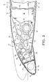
- the support and actuating assembly of the present invention functions to move the nose section 22 from an upper cruise position shown in Figure 1, through an intermediate position of Figure 3, to a fully deflected high lift position, shown in Figure 5. This is accomplished in a manner that as the assembly 10 moves from the position of Figure 1 to that of Figure 5, the curvature of the upper skin panel 28 progressively increases so as to assume a proper aerodynamic contour throughout the movement of the assembly 10 from its cruise configuration to its fully downwardly deflected position. During such downward movement, the forward lower skin portion 38 moves downwardly with the nose section 22 to separate from the rear portion 40, with the rear edge of the lower skin portion 38 moving rearwardly beneath the rear lower skin portion 40.
- a beam assembly which functions as a locating device, generally designated 45.
- a beam assembly which functions as a locating device, generally designated 45.
- the support and actuating assembly 44 there will first be a detailed description of the support and actuating assembly 44, after which the locating device 45 will be described.
- the support and actuating assembly 44 comprises a generally arcuately shaped cam track 46, having a forward cam track portion 48 and a rear cam track portion 50.
- a forward cam track locating means comprising upper and lower cam rollers 52 and 54, engaging upper and lower cam track surfaces 56 and 58, respectively, of the forward track portion 48.
- a rear locating and drive means comprising an upper cam roller 60, and a lower combined cam roller and drive gear 62.
- the upper rear cam roller 60 engages an upper surface of the rear cam track portion 50.
- the combined roller/drive member 62 comprises a gear portion 64 made up of gear teeth 66, and a roller portion having two circular surfaces 68.
- the cam track 46 is made in right and left sections, spaced a short distance from one another.
- the teeth 66 of the roller/drive member 62 are positioned between the two sides of the roller surface 68 of the member 62.
- This gear segment 70 has teeth 72 which engage the teeth 66 of the roller/drive member 62.
- the forward end of the cam track 46 is formed to fit between a clevis 74, which is a part of the nose section 22, and these are rigidly interconnected at two connecting locations 76.
- the cam rollers 52, 54 and 60, and also the roller/drive member 62 are rotatably mounted to a stationary support rib 78 which is fixedly connected to and extends forwardly from the front spar 20.
- the cam track 46 has a generally arcuate configuration, and has a circumferential or lengthwise axis which, for purposes of illustration, has been drawn as a circular arc, indicated at 80 in Figure 8, and having a center of curvature at 82.
- the actual configuration of the track 46 deviates slightly from a true circular arc so as to program the movement of the nose section 22 more precisely so as to obtain the proper degree of curvature of the upper skin panel 28 throughout its movement from the cruise position of Figure 1, through the intermediate position of Figure 3, to the full down position of Figure 5, while maintaining proper engagement of the gear teeth 66 with the teeth 72 of the gear segment 70.
- the cam rollers 52 and 54 are positioned substantially opposite one another relative to the circumferential axis 80, and the center axes of the rollers 52 and 54 are positioned along a line 84 that slants upwardly and rearwardly toward the center of curvature 82.
- the center axis of the upper cam roller 60 and the center axis of the roller/drive member 62 are positioned on a line 86 that extends upwardly and forwardly toward the center of curvature 82.
- the track 46 is at its forwardmost position, so that the forward rollers 52 and 54 engage the lower rear portion of the forward cam track section 48, and the rear upper roller 60 and the roller/drive member 62 engage the upper rear portion of the rear cam track section 50.
- the rollers 52, 54, 60 and 68 are arranged in a suitable support structure which has side load pads that engage lateral surfaces of the cam track 46 to keep the track 46 properly located relative to the roller 52, 54 and 60, as well as properly located relative to the roller/drive member 62.
- the track 46 is provided with suitable stop means which limits forward and rearward travel of the track 46.
- the clevis 74 acts as a stop member relative to the lower front roller 54 to limit rearward movement of the track 46.
- the support and actuating assembly 44 is shown at only one spanwise location of the wing 10. It is to be understood that there are similar assemblies 44 at other spanwise locations along the length of the wing 12.
- the roller/drive members 62 at these various spanwise locations can be interconnected by a drive shaft so as to be driven from a common power source.
- the roller/drive member 62 is rotated clockwise, as seen in Figure 1.
- This causes the cam track 46 to travel in a path generally following (but deviating somewhat from) the arc approximated by the arcuate axis 80 of the track 46, so that the instantaneous center of rotation of the track 46 and the nose section 22 remains reasonably close to the center of curvature 82 of the axis or arc 80, but moves relative to the center 82.
- the support and drive assembly 44 reaches the intermediate position of Figure 3
- the nose section 22 has moved downwardly and moderately rearwardly, and also has rotated so that it is at more of a downward and forward slant.
- the amount of rotation from Figure 1 is 20°.
- the movement of the nose section 22 has been such so that the forward part 30 and the rear part 32 of the skin panel 28 have moved moderately closer to one another so as to place the flexible intermediate portion 36 of the panel 28 in a rather moderate curve, as shown in Figure 3.
- This curvature is such that it forms a proper aerodynamic contour of the upper skin section extending from the nose section 22 to the location of the forward spar 20.
- Further clockwise rotation of the roller/drive member 62 causes the cam track 46 to move further rearwardly so.as to deflect the nose section 22 yet further downwardly to the 38.5° deflected position of Figure 5.
- FIG 7 illustrates somewhat schematically the results of an analysis of the changing geometry of the flexible upper skin panel 28 during the downward deflection of the nose section 22.
- the points A and C are at, respectively, the rear and forward portions of the bendable panel section 28, while the point B is a variable intermediate point.
- Figure 7 is not intended to give the precise results of the analysis, but rather to indicate the nature of the angular relationships that were studied. This analysis indicates that throughout not only the three positions shown on Figure 7, but also throughout the other intermediate positions, the curvature of the upper panel 28 produces the desired aerodynamic contour.
- Figure 9 is a schematic illustration of the geometry of the track 46, relative to the cam rollers 52, 54 and 60, and also relative to the cam roller 68 of the roller/drive member 62.
- the respective centers of rotation of these members 52, 54, 60 and 68 are designated by the letters "L”, “M”, “N” and "H”.
- the forward cam track portion 48 has its upper and lower surfaces 56 and 58 deflected radially outwardly from the center of curvature 82 of the arc 80.
- the path of the four center points, H and L-N, are illustrated by a series of "x" points which show instantaneous locations of these four centers H and L-N for various angular deflections of the assembly 10.
- the instantaneous center of rotation of the centers of the rollers 52, 54, 60 and the cam surface 68 relative to the track 46 is designated "E", and at the 0° position, the location of'E is designated E 0 .
- E The instantaneous center of rotation of the centers of the rollers 52, 54, 60 and the cam surface 68 relative to the track 46
- E 0 the location of'E
- the instantaneous center of rotation Eo of these components 52, 54, 60 and 68 moves slightly downwardly and forwardly to the location indicated at El.
- the instantaneous center of rotation of these components moves back to the initial position indicated at E 0 .
- the movement of the nose section 22 is such that the upper skin panel 28 is continuously flexed to the desired aerodynamic contour for all positions. Further, the geometry of this mechanism introduces no tensile or compression forces into the plane of the upper skin panel 28, but only the bending moments due to flexing. Further, this contouring of the panel 28 is accomplished with the nose section 22 following a path that.allows the cam track 46 to always remains in proper driving engagement with the roller/drive member 62.
- This device 45 comprises a support beam or locating arm 100 pivotally connected at its forward end 102 to an upper rear portion of the nose section 22.
- the rear end of the arm 100 has a cam roller 104 that rides in a cam 106 of a cam support member 108.
- a panel support or locating link 110 which has a lower end pivotally connected at 112 to the arm 100 at a location slightly behind the midlength thereof.
- the upper end 114 of the link 110 is pivotally connected to a spanwise stiffener 116 which, in cross-sectional configuration, comprises two right angle members joined to each other. This stiffener connects to the inside surface of the panel 28.
- the precise location of the arm 100 is at all times controlled by the position of the nose section 22 and the programming of the cam 106.
- the locating link 110 will always be properly located to position its connecting point 114 to the stiffener 116 at the proper location to obtain the desired aerodynamic contour of the upper skin panel 28.
Landscapes
- Engineering & Computer Science (AREA)
- Mechanical Engineering (AREA)
- Aviation & Aerospace Engineering (AREA)
- Body Structure For Vehicles (AREA)
- Automobile Manufacture Line, Endless Track Vehicle, Trailer (AREA)
Abstract
Description
- The present invention relates to airfoils,. and more particularly to a variable camber leading edge assembly for an airfoil.
- This is a continuation-in-part of a pending application filed as PCT/US 82/01797, and U.S.S.N. 747,652, filed December 28, 1982.
- A common way of modifying the lift characteristics of an airfoil for low speed operation is to use leading edge devices which either pivot or slide outwardly from the leading edge of the airfoil to a deployed position. With many such devices, there is a problem that during deployment there is an interruption of smooth airflow over the upper surface of the airfoil. Also, many such devices are not able to be deployed to intermediate positions while maintaining the proper flow of air over the airfoil.
- Accordingly, there have appeared in the prior art various devices to vary the shape of the airfoil itself in a manner to vary the camber of the leading edge. Variable camber leading edges are particularly desirable in solving the airfoil stall problem for small, thin, swept-back wings which have good cruise performance, but require high lift devices to make their low speed performance acceptable. However, there is a problem of installing such variable camber leading edge devices on such wings since these thin wings have the least space available in which to house such devices.
- Accordingly, it is an object of the present invention to provide a device to vary the camber of an airfoil, and particularly such a device used as a variable camber leading edge assembly. It is a more particular object to provide such an assembly with a flexible upper skin panel which is moved from a cruise position to a more curved high lift position, with the flexible panel having a desired aerodynamic contour throughout its path of travel between the upper cruise position and the downwardly deflected position, with the assembly being relatively compact, and with the major part of the aerodynamic load on the assembly being transmitted into the support structure so as to relieve loading on the drive mechanism of the assembly.
- The leading edge assembly of the present invention is for an airfoil having an upper surface, a lower surface, a leading edge and a trailing edge. The assembly comprises a main support structure for the airfoil, and a nose section at the leading edge. There is an upper skin panel having a rear part connected to the structure, a forward part connected to the nose section, and an intermediate flexible panel portion extending between the rear part and the forward part.
- There is a support and actuating means operatively connected between the nose section and the support structure to move the nose section about a general center of rotation between a first upper position where the flexible panel portion has a less-r degree of curvature and the nose section is more horizontally aligned to a second lower position where the flexible panel portion has a greater degree of curvature and the nose section is aligned in a more downward slant. Thus, the curvature of the flexible panel portion increases with movement of the nose section toward its second position.
- The support and actuating means comprises a cam track having a forward end connected to the nose section and having a lengthwise axis curved in a generally arcuate configuration about the general center of rotation. There is cam track contact means connecting to the support structure and comprising a forward contact portion and a rear contact portion engaging the cam track at two spaced locations along the lengthwise axis to restrain angular movement of the cam track relative to the cam track contact means. The cam track has a forward cam track section engaging the forward contact portion for travel along a path having a forward and upward slant, and a rear cam track section engaging the rear contact portion for travel along a path having an upward and rearward slant.
- There is a rotatably mounted drive gear member engaging the cam track at a drive location which is adjacent to and radially outwardly of the cam track section relative to the general center of rotation.
- The lengthwise axis of the cam track at the forward cam section deviates at least partly from a true circular arc, in a manner that said general center of rotation shifts during movement of the nose section between the first and second positions, whereby a proper aerodynamic contour of the upper skin panel can be maintained.
- Desirably, the drive gear member is adjacent the rear contact portion, and the rear cam track section comprises a gear segment engaging the drive gear member. The gear segment is arranged in a circular arc. Also, in the preferred form, the drive gear member has an axis of rotation which is coincident an axis of rotation of a lower contact member of the rear contact portion.
- The forward section of the cam track has a forward portion, a middle portion, and a rear portion. The middle portion of the forward section deviates from the arcuate configuration of the lengthwise axis of the cam track in a direction radially outwardly from the general center of rotation.
- In the specific configuration shown herein, the forward contact portion comprises upper and lower cam rollers engaging upper and lower surfaces, respectively, of the forward cam track section. Likewise, the rear contact portion comprises upper and lower rollers engaging upper and lower cam surfaces of the rear cam track section.
- As another feature of the present invention, there is locating means comprising a locating member having first and second end portions. The first,end portion is pivotally connected to one of the nose section and the main support structure. The second end portion is operatively connected to cam means arranged to move the second end portion along a predetermined path as the nose section moves between its first and second positions. The locating means further comprises a locating link operatively connected between the locating member and the upper skin panel at a location intermediate the forward and rear parts of the skin panel.
- More specifically, the first end of the locating member is pivotally connected to the nose section, and the second end of the locating member is connected to a cam member defining a cam path operatively engaging a matching cam member connected to the second end of the locating member. The cam member is connected to the main support structure.
- Other features of the present invention will become apparent from the following detailed description.
-
- Figure 1 is a cord-wise sectional view of an actuating assembly of the leading edge assembly of the present invention in its upper position for cruise mode;
- Figure 2 is a cord-wise sectional view of a positioning device of the leading assembly of the present invention;
- Figures 3 and 5 are views similar to Figure 1, but showing the leading edge assembly deflected downwardly at 20° and 38.5° angles, respectively;
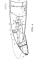
- Figures 4 and 6 are views similar to Figure 2, showing the leading edge assembly deflected downwardly at angles of 20° and 38.5°, respectively;
- Figure 7 is a schematic.view of the outer contours of the leading edge assembly, illustrating various angles of curvature for different positions of the leading edge assembly;
- Figure 8 is,a schematic view of the actuating assembly of the present invention, and illustrating the positioning of the drive gear and the cam rollers;
- Figure 9 is a schematic view illustrating the paths followed by the cam rollers and the drive gear of the actuating assembly, where the cam track of the actuating assembly is presumed to be stationary, and the cam rollers and drive gear move relative to the cam track; and
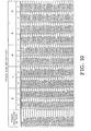
- Figure 10 is a table giving coordinates for various point locations along the paths of movement illustrated in Figure 9.
- The leading
edge assembly 10 of the present invention forms the forward portion of awing 12, only the forward portion which is shown. Thewing 12 has anupper surface 14, alower surface 16, a leadingedge 18 and a trailing edge (not shown for ease of . illustration). Thewing 12 has a main support structure comprising afront spar 20 to which the leadingedge assembly 10 is mounted. At the leadingedge 18, there is anose section 22 in the form of a substantially rigid beam extending in a spanwise direction along the leadingedge 18. Thenose section 22 has anupper surface 24 and alower surface 26. There is a flexibleupper skin panel 28 which has: a) aforward part 30 which is attached to the upper rear surface of thenose section 22 and blends into theupper surface 24 of thenose section 22; b) arear part 32 which butts against, and is aligned with, the mainupper skin 34 at the location of thefront spar 20, and c) a flexibleintermediate portion 36 which reaches between thefront part 30 and therear part 32. - The lower surface of the leading
edge assembly 10 comprises aforward portion 38 connected to and extending rearwardly from the lower surface of thenose section 22, and arear portion 40 which is a forward extension of the mainlower skin section 41 at the lower part of thefront spar 20. At the front edge of therear portion 40, there is aseal 42 to close the small gap at the juncture of thelower skin portions - The support and actuating assembly of the present invention, generally designated 44, functions to move the
nose section 22 from an upper cruise position shown in Figure 1, through an intermediate position of Figure 3, to a fully deflected high lift position, shown in Figure 5. This is accomplished in a manner that as theassembly 10 moves from the position of Figure 1 to that of Figure 5, the curvature of theupper skin panel 28 progressively increases so as to assume a proper aerodynamic contour throughout the movement of theassembly 10 from its cruise configuration to its fully downwardly deflected position. During such downward movement, the forwardlower skin portion 38 moves downwardly with thenose section 22 to separate from therear portion 40, with the rear edge of thelower skin portion 38 moving rearwardly beneath the rearlower skin portion 40. - To properly locate and support the flexible
intermediate portion 36 of theupper skin panel 28, there is illustrated in Figures 2, 4 and 6 a beam assembly, which functions as a locating device, generally designated 45. In the following description, there will first be a detailed description of the support and actuatingassembly 44, after which the locatingdevice 45 will be described. - The support and actuating
assembly 44 comprises a generally arcuately shapedcam track 46, having a forwardcam track portion 48 and a rearcam track portion 50. There is a forward cam track locating means comprising upper andlower cam rollers cam track surfaces forward track portion 48. - There is a rear locating and drive means comprising an
upper cam roller 60, and a lower combined cam roller and drivegear 62. The upperrear cam roller 60 engages an upper surface of the rearcam track portion 50. The combined roller/drive member 62 comprises agear portion 64 made up ofgear teeth 66, and a roller portion having twocircular surfaces 68. - The
cam track 46 is made in right and left sections, spaced a short distance from one another. Thus, theteeth 66 of the roller/drive member 62 are positioned between the two sides of theroller surface 68 of themember 62. There is provided agear segment 70 positioned between and bolted to the two sections of thecam track 46. Thisgear segment 70 hasteeth 72 which engage theteeth 66 of the roller/drive member 62. - The forward end of the
cam track 46 is formed to fit between aclevis 74, which is a part of thenose section 22, and these are rigidly interconnected at two connectinglocations 76. Thecam rollers drive member 62 are rotatably mounted to astationary support rib 78 which is fixedly connected to and extends forwardly from thefront spar 20. - The
cam track 46 has a generally arcuate configuration, and has a circumferential or lengthwise axis which, for purposes of illustration, has been drawn as a circular arc, indicated at 80 in Figure 8, and having a center of curvature at 82. However, for reasons which will be explained more fully hereinafter, the actual configuration of thetrack 46 deviates slightly from a true circular arc so as to program the movement of thenose section 22 more precisely so as to obtain the proper degree of curvature of theupper skin panel 28 throughout its movement from the cruise position of Figure 1, through the intermediate position of Figure 3, to the full down position of Figure 5, while maintaining proper engagement of thegear teeth 66 with theteeth 72 of thegear segment 70. - The
cam rollers circumferential axis 80, and the center axes of therollers line 84 that slants upwardly and rearwardly toward the center ofcurvature 82. The center axis of theupper cam roller 60 and the center axis of the roller/drive member 62 are positioned on aline 86 that extends upwardly and forwardly toward the center ofcurvature 82. - In the cruise position of Figure 1, the
track 46 is at its forwardmost position, so that theforward rollers cam track section 48, and the rearupper roller 60 and the roller/drive member 62 engage the upper rear portion of the rearcam track section 50. Although not illustrated herein, it is to be understood that therollers cam track 46 to keep thetrack 46 properly located relative to theroller drive member 62. Also, thetrack 46 is provided with suitable stop means which limits forward and rearward travel of thetrack 46. For example, theclevis 74 acts as a stop member relative to the lowerfront roller 54 to limit rearward movement of thetrack 46. - Further, it is to be understood that the support and actuating
assembly 44 is shown at only one spanwise location of thewing 10. It is to be understood that there aresimilar assemblies 44 at other spanwise locations along the length of thewing 12. The roller/drive members 62 at these various spanwise locations can be interconnected by a drive shaft so as to be driven from a common power source. - In operation, to move the
assembly 10 from the upper cruise position of Figure 1, the roller/drive member 62 is rotated clockwise, as seen in Figure 1. This causes thecam track 46 to travel in a path generally following (but deviating somewhat from) the arc approximated by thearcuate axis 80 of thetrack 46, so that the instantaneous center of rotation of thetrack 46 and thenose section 22 remains reasonably close to the center ofcurvature 82 of the axis orarc 80, but moves relative to thecenter 82. When the support and driveassembly 44 reaches the intermediate position of Figure 3, thenose section 22,has moved downwardly and moderately rearwardly, and also has rotated so that it is at more of a downward and forward slant. In the particular configuration of Figure 3, the amount of rotation from Figure 1 is 20°. Further, at this location the movement of thenose section 22 has been such so that theforward part 30 and therear part 32 of theskin panel 28 have moved moderately closer to one another so as to place the flexibleintermediate portion 36 of thepanel 28 in a rather moderate curve, as shown in Figure 3. This curvature is such that it forms a proper aerodynamic contour of the upper skin section extending from thenose section 22 to the location of theforward spar 20. Further clockwise rotation of the roller/drive member 62 causes thecam track 46 to move further rearwardly so.as to deflect thenose section 22 yet further downwardly to the 38.5° deflected position of Figure 5. - Reference is now made to Figure 7, which illustrates somewhat schematically the results of an analysis of the changing geometry of the flexible
upper skin panel 28 during the downward deflection of thenose section 22. The points A and C are at, respectively, the rear and forward portions of thebendable panel section 28, while the point B is a variable intermediate point. - Certain radii and angles of curvature are illustrated in Figure 7, and these were determined by an iterative solution to simultaneous equations involving the panel length and tangency at all three points, A, B, and C, these equations being the following:
- a) Constant arc length of ACo.

- b) Common radial (BGD) at intersection of R1 and R2.

- c) The vertical component of arc AB plus that for arc BC equals the vertical coordinate of boint C.

- ACo. is equal to the arc distance from point A to point Co. (which arc distance remains constant throughout movement of the assembly).
- α1 is equal to the angle formed by the radii extending from points A and B (this angle being shown for three different positions of the leading edge assembly)
- AC is the arc distance from point A to point C.
- k is a constant which equals to 360 2n
- a is equal to the angle formed by the radii drawn from point A and point C.
- R2 equals the distance from G to B (which is the same as the distance from G to C).
- R1 equals the distance from point A to point D (with point D being shown at three different locations, namely D-1, D-2 and D-3).
- CF is equal to the distance from point C to point F.
- AF is equal to the distance from point A to point F.
- Zc is equal to the vertical distance of the point C below the point A.
- Figure 7 is not intended to give the precise results of the analysis, but rather to indicate the nature of the angular relationships that were studied. This analysis indicates that throughout not only the three positions shown on Figure 7, but also throughout the other intermediate positions, the curvature of the
upper panel 28 produces the desired aerodynamic contour. - To explain more fully how this is accomplished in the present invention, reference is now made to Figure 9, which is a schematic illustration of the geometry of the
track 46, relative to thecam rollers cam roller 68 of the roller/drive member 62. The respective centers of rotation of thesemembers - In the illustration of Figure 9, the assumption has been made that the
track 46 and thenose section 22 remain stationary, while therollers drive member 62 are the movable members. The paths of the various center points, L, H, N, and H are shown at the 0° deflected position (with a "0" suffix designating that location), and also at the fully deflected position (where a "38.5" suffix designates that fully deflected location). Also, thecircular arc 80 has been illustrated in Figure 9 to provide a visual comparison with the deviations of thetrack 46 from a true circular curve. - It can be seen that the forward
cam track portion 48 has its upper andlower surfaces curvature 82 of thearc 80. The path of the four center points, H and L-N, are illustrated by a series of "x" points which show instantaneous locations of these four centers H and L-N for various angular deflections of theassembly 10. - The instantaneous center of rotation of the centers of the
rollers cam surface 68 relative to thetrack 46 is designated "E", and at the 0° position, the location of'E is designated E0. During the travel from approximately the 0° position to about the mid-deflection point (i.e. at about 18-20° deflection), the instantaneous center of rotation Eo of thesecomponents - These various locations are presented in the Table of Figure 10, which gives these various locations of the points E, H, L and M in terms' of vertical and horizontal coordinates. A numerical increase along the Z axis indicates downward movement, while a numerical increase along the X axis indicates a forward movement.
- From the above discussion, it can be recognized that as the
cam track 46 moves along its circumferential orarcuate axis 80, thetrack 46 will have what might he described as a moderate rocking movement (about point Ho). This rocking movement is such that the point oftangency 96 of the roller/drive member 62 rotates moderately clockwise about point Ho. - It has been found that with the arrangement illustrated in Figure 9, the movement of the
nose section 22 is such that theupper skin panel 28 is continuously flexed to the desired aerodynamic contour for all positions. Further, the geometry of this mechanism introduces no tensile or compression forces into the plane of theupper skin panel 28, but only the bending moments due to flexing. Further, this contouring of thepanel 28 is accomplished with thenose section 22 following a path that.allows thecam track 46 to always remains in proper driving engagement with the roller/drive member 62. - Another facet of the present invention will now be described with reference to Figures 2, 4 and 6, which show the locating
device 45 in three different positions, namely, the 0° position of Figure 2, the 20° deflected position of Figure 4, and the 38.5° deflected position of Figure 6. Thisdevice 45 comprises a support beam or locatingarm 100 pivotally connected at itsforward end 102 to an upper rear portion of thenose section 22. The rear end of thearm 100 has acam roller 104 that rides in acam 106 of acam support member 108. - There is a panel support or locating
link 110 which has a lower end pivotally connected at 112 to thearm 100 at a location slightly behind the midlength thereof. Theupper end 114 of thelink 110 is pivotally connected to aspanwise stiffener 116 which, in cross-sectional configuration, comprises two right angle members joined to each other. This stiffener connects to the inside surface of thepanel 28. - It can readily be appreciated that the precise location of the
arm 100 is at all times controlled by the position of thenose section 22 and the programming of thecam 106. Thus, the locatinglink 110 will always be properly located to position its connectingpoint 114 to thestiffener 116 at the proper location to obtain the desired aerodynamic contour of theupper skin panel 28. - While the present invention is particularly adapted to be used in, and to uniquely resolve the problems of, a variable camber leading edge assembly of an airfoil, within the broader aspects of the present invention, it could be utilized in other arrangements relative to an airfoil or similar device. Specifically, in the following claims, it is to be understood that while this assembly is recited as a leading edge assembly, the term "leading edge assembly" is to be interpreted broadly enough to refer to an assembly positioned at the trailing edge of an airfoil, in which case the terms "forward" and "rear" would be reversed within the meaning of the claims. Also, it is to be understood that various modifications could be made without departing from the basic teachings of the present invention.
Claims (14)
said locating means comprising:
Applications Claiming Priority (2)
| Application Number | Priority Date | Filing Date | Title |
|---|---|---|---|
| US658674 | 1984-10-09 | ||
| US06/658,674 US4706913A (en) | 1982-12-28 | 1984-10-09 | Variable camber leading edge assembly for an airfoil |
Related Child Applications (1)
| Application Number | Title | Priority Date | Filing Date |
|---|---|---|---|
| EP87117677.2 Division-Into | 1987-11-30 |
Publications (2)
| Publication Number | Publication Date |
|---|---|
| EP0177979A1 true EP0177979A1 (en) | 1986-04-16 |
| EP0177979B1 EP0177979B1 (en) | 1989-11-15 |
Family
ID=24642189
Family Applications (2)
| Application Number | Title | Priority Date | Filing Date |
|---|---|---|---|
| EP87117677A Expired EP0302143B1 (en) | 1984-10-09 | 1985-05-20 | Variable camber leading edge assembly for an airfoil |
| EP85200804A Expired EP0177979B1 (en) | 1984-10-09 | 1985-05-20 | Variable camber leading edge assembly for an airfoil |
Family Applications Before (1)
| Application Number | Title | Priority Date | Filing Date |
|---|---|---|---|
| EP87117677A Expired EP0302143B1 (en) | 1984-10-09 | 1985-05-20 | Variable camber leading edge assembly for an airfoil |
Country Status (3)
| Country | Link |
|---|---|
| US (1) | US4706913A (en) |
| EP (2) | EP0302143B1 (en) |
| DE (2) | DE3585235D1 (en) |
Cited By (3)
| Publication number | Priority date | Publication date | Assignee | Title |
|---|---|---|---|---|
| EP2256032A2 (en) | 2009-05-25 | 2010-12-01 | Deutsches Zentrum für Luft- und Raumfahrt e.V. | Aerodynamic component with deformable skin |
| EP1398269B2 (en) † | 2002-09-10 | 2015-02-11 | The Boeing Company | Method and apparatus for controlling airflow with a leading edge device having a flexible flow surface |
| US9896188B1 (en) * | 2013-12-04 | 2018-02-20 | The United States Of America As Represented By The Secretary Of The Air Force | Variable camber adaptive compliant wing system |
Families Citing this family (48)
| Publication number | Priority date | Publication date | Assignee | Title |
|---|---|---|---|---|
| US5004189A (en) * | 1988-08-31 | 1991-04-02 | Igram Dale J | Reconfigurable airfoil |
| US6048581A (en) | 1996-09-24 | 2000-04-11 | Mcdonnell Douglas Corporation | Elastic ground plane and method |
| USRE44313E1 (en) | 1996-10-22 | 2013-06-25 | The Boeing Company | Airplane with unswept slotted cruise wing airfoil |
| US6209824B1 (en) | 1997-09-17 | 2001-04-03 | The Boeing Company | Control surface for an aircraft |
| DE10001700B4 (en) * | 2000-01-18 | 2005-11-24 | Deutsches Zentrum für Luft- und Raumfahrt e.V. | Aerodynamic component with variable geometry |
| US6634594B1 (en) * | 2002-05-03 | 2003-10-21 | The Boeing Company | Hypersonic waverider variable leading edge flaps |
| US7258308B2 (en) | 2002-07-02 | 2007-08-21 | The Boeing Company | Method and apparatus for controlling airflow with a gapped trailing edge device having a flexible flow surface |
| US7243881B2 (en) | 2003-06-03 | 2007-07-17 | The Boeing Company | Multi-function trailing edge devices and associated methods |
| US7059563B2 (en) | 2003-06-03 | 2006-06-13 | The Boeing Company | Systems, apparatuses, and methods for moving aircraft control surfaces |
| US6799739B1 (en) | 2003-11-24 | 2004-10-05 | The Boeing Company | Aircraft control surface drive system and associated methods |
| US7424350B2 (en) | 2004-02-02 | 2008-09-09 | The Boeing Company | Vehicle control systems and corresponding sizing methods |
| US7357358B2 (en) | 2004-02-27 | 2008-04-15 | The Boeing Company | Aircraft leading edge device systems and corresponding sizing methods |
| GB0410375D0 (en) | 2004-05-10 | 2004-06-16 | Airbus Uk Ltd | High lift device for an aircraft |
| US7270305B2 (en) | 2004-06-15 | 2007-09-18 | The Boeing Company | Aircraft leading edge apparatuses and corresponding methods |
| US6978971B1 (en) | 2004-06-15 | 2005-12-27 | The Boeing Company | Methods and apparatuses for controlling airflow proximate to engine/airfoil systems |
| US7494094B2 (en) | 2004-09-08 | 2009-02-24 | The Boeing Company | Aircraft wing systems for providing differential motion to deployable lift devices |
| US7264206B2 (en) | 2004-09-30 | 2007-09-04 | The Boeing Company | Leading edge flap apparatuses and associated methods |
| US7322547B2 (en) | 2005-01-31 | 2008-01-29 | The Boeing Company | Aerospace vehicle leading edge slat devices and corresponding methods |
| US7338018B2 (en) | 2005-02-04 | 2008-03-04 | The Boeing Company | Systems and methods for controlling aircraft flaps and spoilers |
| US7309043B2 (en) | 2005-04-27 | 2007-12-18 | The Boeing Company | Actuation device positioning systems and associated methods, including aircraft spoiler droop systems |
| US7721999B2 (en) | 2005-05-20 | 2010-05-25 | The Boeing Company | Aerospace vehicle fairing systems and associated methods |
| US7300021B2 (en) | 2005-05-20 | 2007-11-27 | The Boeing Company | Aerospace vehicle fairing systems and associated methods |
| DE102005027749B4 (en) * | 2005-06-16 | 2011-07-28 | Airbus Operations GmbH, 21129 | Buoyancy-enhancing flap, in particular nose flap, for an aerodynamically effective wing |
| US7367530B2 (en) | 2005-06-21 | 2008-05-06 | The Boeing Company | Aerospace vehicle yaw generating systems and associated methods |
| US7500641B2 (en) | 2005-08-10 | 2009-03-10 | The Boeing Company | Aerospace vehicle flow body systems and associated methods |
| US7611099B2 (en) | 2005-09-07 | 2009-11-03 | The Boeing Company | Seal assemblies for use with drooped spoilers and other control surfaces on aircraft |
| US7708231B2 (en) | 2005-11-21 | 2010-05-04 | The Boeing Company | Aircraft trailing edge devices, including devices having forwardly positioned hinge lines, and associated methods |
| US7475854B2 (en) | 2005-11-21 | 2009-01-13 | The Boeing Company | Aircraft trailing edge devices, including devices with non-parallel motion paths, and associated methods |
| TR201900555T4 (en) | 2006-04-27 | 2019-02-21 | Flexsys Inc | Harmonious structure design for variable surface contours. |
| US7578484B2 (en) | 2006-06-14 | 2009-08-25 | The Boeing Company | Link mechanisms for gapped rigid krueger flaps, and associated systems and methods |
| GB0722425D0 (en) * | 2007-11-15 | 2007-12-27 | Airbus Uk Ltd | Slat support funk plate |
| US7954769B2 (en) | 2007-12-10 | 2011-06-07 | The Boeing Company | Deployable aerodynamic devices with reduced actuator loads, and related systems and methods |
| US7766282B2 (en) | 2007-12-11 | 2010-08-03 | The Boeing Company | Trailing edge device catchers and associated systems and methods |
| GB0810460D0 (en) | 2008-06-09 | 2008-07-09 | Airbus Uk Ltd | Support assembly |
| US8256719B2 (en) * | 2008-12-01 | 2012-09-04 | The Boeing Company | Shape changing airfoil system |
| US8226048B2 (en) | 2008-12-09 | 2012-07-24 | The Boeing Company | Link mechanisms, including Stephenson II link mechanisms for multi-position flaps and associated systems and methods |
| US8500060B2 (en) * | 2009-02-10 | 2013-08-06 | The Boeing Company | Aircraft with a pressurized vessel |
| US8056865B2 (en) | 2009-03-05 | 2011-11-15 | The Boeing Company | Mechanism for changing the shape of a control surface |
| US8382045B2 (en) | 2009-07-21 | 2013-02-26 | The Boeing Company | Shape-changing control surface |
| GB201101274D0 (en) | 2011-01-25 | 2011-03-09 | Airbus Operations Ltd | Leading edge device for an aircraft |
| US8650811B2 (en) | 2011-02-04 | 2014-02-18 | The Boeing Company | Solar collector frame |
| WO2013172914A2 (en) * | 2012-02-27 | 2013-11-21 | Sinhatech | Self adjusting deturbulator enhanced flap and wind deflector |
| US8925870B1 (en) * | 2012-03-09 | 2015-01-06 | The Boeing Company | Morphing wing leading edge |
| US9598167B2 (en) | 2014-03-04 | 2017-03-21 | The Boeing Company | Morphing airfoil leading edge |
| US9415856B2 (en) * | 2014-06-04 | 2016-08-16 | The Boeing Company | Dual-rib morphing leading edge |
| GB201522486D0 (en) * | 2015-12-21 | 2016-02-03 | Airbus Operations Ltd | Seal assembly |
| KR101858837B1 (en) * | 2016-10-21 | 2018-06-27 | 윤영준 | System and method of altering leading edge of airfoil |
| EP4063258A3 (en) * | 2021-03-23 | 2023-02-22 | Airbus Operations GmbH | Wing for an aircraft |
Citations (4)
| Publication number | Priority date | Publication date | Assignee | Title |
|---|---|---|---|---|
| US4131253A (en) * | 1977-07-21 | 1978-12-26 | The Boeing Company | Variable camber trailing edge for airfoil |
| FR2416165A1 (en) * | 1978-02-01 | 1979-08-31 | Grob Burkhart | WING WITH SHUTTERS |
| US4427168A (en) * | 1981-09-29 | 1984-01-24 | The Boeing Company | Variable camber leading edge mechanism with Krueger flap |
| US4475702A (en) * | 1982-12-28 | 1984-10-09 | The Boeing Company | Variable camber leading edge assembly for an airfoil |
Family Cites Families (12)
| Publication number | Priority date | Publication date | Assignee | Title |
|---|---|---|---|---|
| US1917428A (en) * | 1927-12-17 | 1933-07-11 | Uppercu Burnelli Corp | Aircraft |
| US1773530A (en) * | 1929-09-03 | 1930-08-19 | Hannah Mark Owen | Expanding wing for aeroplanes |
| US1868748A (en) * | 1931-11-28 | 1932-07-26 | Herbert J Hogan | Variable camber airfoil |
| US2786907A (en) * | 1955-04-27 | 1957-03-26 | John L Harris | Control device |
| US3089666A (en) * | 1961-04-13 | 1963-05-14 | Boeing Co | Airplane having changeable thrust direction |
| US3716209A (en) * | 1970-06-01 | 1973-02-13 | Mini Of Technology | Fluid dynamic lift generating or control force generating structures |
| GB1596642A (en) * | 1977-04-06 | 1981-08-26 | British Aerospace | Aircraft wings |
| US4171787A (en) * | 1977-07-21 | 1979-10-23 | Zapel Edwin J | Variable camber leading edge for airfoil |
| GB2006133B (en) * | 1977-09-21 | 1982-01-06 | British Aircraft Corp Ltd | Aircraft wings |
| US4351502A (en) * | 1980-05-21 | 1982-09-28 | The Boeing Company | Continuous skin, variable camber airfoil edge actuating mechanism |
| EP0045988B2 (en) * | 1980-08-13 | 1993-10-06 | The Boeing Company | Extendible airfoil track assembly |
| WO1984002506A1 (en) * | 1982-12-28 | 1984-07-05 | Boeing Co | Variable camber leading edge assembly for an airfoil |
-
1984
- 1984-10-09 US US06/658,674 patent/US4706913A/en not_active Expired - Fee Related
-
1985
- 1985-05-20 EP EP87117677A patent/EP0302143B1/en not_active Expired
- 1985-05-20 EP EP85200804A patent/EP0177979B1/en not_active Expired
- 1985-05-20 DE DE8787117677T patent/DE3585235D1/en not_active Expired - Lifetime
- 1985-05-20 DE DE8585200804T patent/DE3574243D1/en not_active Expired
Patent Citations (4)
| Publication number | Priority date | Publication date | Assignee | Title |
|---|---|---|---|---|
| US4131253A (en) * | 1977-07-21 | 1978-12-26 | The Boeing Company | Variable camber trailing edge for airfoil |
| FR2416165A1 (en) * | 1978-02-01 | 1979-08-31 | Grob Burkhart | WING WITH SHUTTERS |
| US4427168A (en) * | 1981-09-29 | 1984-01-24 | The Boeing Company | Variable camber leading edge mechanism with Krueger flap |
| US4475702A (en) * | 1982-12-28 | 1984-10-09 | The Boeing Company | Variable camber leading edge assembly for an airfoil |
Cited By (4)
| Publication number | Priority date | Publication date | Assignee | Title |
|---|---|---|---|---|
| EP1398269B2 (en) † | 2002-09-10 | 2015-02-11 | The Boeing Company | Method and apparatus for controlling airflow with a leading edge device having a flexible flow surface |
| EP2256032A2 (en) | 2009-05-25 | 2010-12-01 | Deutsches Zentrum für Luft- und Raumfahrt e.V. | Aerodynamic component with deformable skin |
| DE102009026457A1 (en) | 2009-05-25 | 2010-12-09 | Eads Deutschland Gmbh | Aerodynamic component with deformable outer skin |
| US9896188B1 (en) * | 2013-12-04 | 2018-02-20 | The United States Of America As Represented By The Secretary Of The Air Force | Variable camber adaptive compliant wing system |
Also Published As
| Publication number | Publication date |
|---|---|
| EP0302143B1 (en) | 1992-01-15 |
| DE3574243D1 (en) | 1989-12-21 |
| DE3585235D1 (en) | 1992-02-27 |
| EP0302143A1 (en) | 1989-02-08 |
| US4706913A (en) | 1987-11-17 |
| EP0177979B1 (en) | 1989-11-15 |
Similar Documents
| Publication | Publication Date | Title |
|---|---|---|
| US4706913A (en) | Variable camber leading edge assembly for an airfoil | |
| US4475702A (en) | Variable camber leading edge assembly for an airfoil | |
| US4131253A (en) | Variable camber trailing edge for airfoil | |
| US5158252A (en) | Three-position variable camber Krueger leading edge flap | |
| US4171787A (en) | Variable camber leading edge for airfoil | |
| US4312486A (en) | Variable camber trailing edge for airfoil | |
| US4159089A (en) | Variable camber flap | |
| US4448375A (en) | Folding truss mechanism for trailing edge flaps | |
| US7028948B2 (en) | Apparatus for increase of aircraft lift and maneuverability | |
| US4049219A (en) | Variable pivot trailing edge flap | |
| EP1398269B1 (en) | Method and apparatus for controlling airflow with a leading edge device having a flexible flow surface | |
| CN109153442B (en) | Variable-pitch propeller device and variable thrust aircraft using same | |
| US20030230672A1 (en) | Ornithopter with flexible fuselage | |
| US4040579A (en) | Variable camber leading edge airfoil system | |
| US7063292B2 (en) | Actuation apparatus for a control flap arranged on a trailing edge of an aircraft airfoil | |
| JPS62157896A (en) | Movable blade with variable camber | |
| EP3310652B1 (en) | Aircraft wing system | |
| AU2016278098B2 (en) | Aircraft wing system | |
| CN1026022C (en) | Area-adjustable connecting rod and thrust reversing blade cascade | |
| US4905932A (en) | Rotary wing aircraft shrouded propeller tail assembly | |
| EP4253228A1 (en) | Wing for an aircraft | |
| GB2050262A (en) | Method and mechanism for changing the wingplan geometry of aeroplanes in flight | |
| US11492098B2 (en) | High-lift device, wing, and aircraft | |
| EP0129545B1 (en) | Variable camber leading edge assembly for an airfoil | |
| GB2060520A (en) | Variable Camber Wings |
Legal Events
| Date | Code | Title | Description |
|---|---|---|---|
| PUAI | Public reference made under article 153(3) epc to a published international application that has entered the european phase |
Free format text: ORIGINAL CODE: 0009012 |
|
| AK | Designated contracting states |
Kind code of ref document: A1 Designated state(s): DE FR GB IT NL |
|
| 17P | Request for examination filed |
Effective date: 19861014 |
|
| 17Q | First examination report despatched |
Effective date: 19870710 |
|
| ITF | It: translation for a ep patent filed | ||
| GRAA | (expected) grant |
Free format text: ORIGINAL CODE: 0009210 |
|
| AK | Designated contracting states |
Kind code of ref document: B1 Designated state(s): DE FR GB IT NL |
|
| ET | Fr: translation filed | ||
| REF | Corresponds to: |
Ref document number: 3574243 Country of ref document: DE Date of ref document: 19891221 |
|
| PLBE | No opposition filed within time limit |
Free format text: ORIGINAL CODE: 0009261 |
|
| STAA | Information on the status of an ep patent application or granted ep patent |
Free format text: STATUS: NO OPPOSITION FILED WITHIN TIME LIMIT |
|
| 26N | No opposition filed | ||
| ITTA | It: last paid annual fee | ||
| PGFP | Annual fee paid to national office [announced via postgrant information from national office to epo] |
Ref country code: GB Payment date: 19920429 Year of fee payment: 8 |
|
| PGFP | Annual fee paid to national office [announced via postgrant information from national office to epo] |
Ref country code: FR Payment date: 19920527 Year of fee payment: 8 |
|
| PGFP | Annual fee paid to national office [announced via postgrant information from national office to epo] |
Ref country code: NL Payment date: 19920531 Year of fee payment: 8 |
|
| PGFP | Annual fee paid to national office [announced via postgrant information from national office to epo] |
Ref country code: DE Payment date: 19920601 Year of fee payment: 8 |
|
| PG25 | Lapsed in a contracting state [announced via postgrant information from national office to epo] |
Ref country code: GB Effective date: 19930520 |
|
| PG25 | Lapsed in a contracting state [announced via postgrant information from national office to epo] |
Ref country code: NL Effective date: 19931201 |
|
| NLV4 | Nl: lapsed or anulled due to non-payment of the annual fee | ||
| GBPC | Gb: european patent ceased through non-payment of renewal fee |
Effective date: 19930520 |
|
| PG25 | Lapsed in a contracting state [announced via postgrant information from national office to epo] |
Ref country code: FR Effective date: 19940131 |
|
| PG25 | Lapsed in a contracting state [announced via postgrant information from national office to epo] |
Ref country code: DE Effective date: 19940201 |
|
| REG | Reference to a national code |
Ref country code: FR Ref legal event code: ST |