EP0177527B1 - Two- or multi-component reactor - Google Patents
Two- or multi-component reactor Download PDFInfo
- Publication number
- EP0177527B1 EP0177527B1 EP85901452A EP85901452A EP0177527B1 EP 0177527 B1 EP0177527 B1 EP 0177527B1 EP 85901452 A EP85901452 A EP 85901452A EP 85901452 A EP85901452 A EP 85901452A EP 0177527 B1 EP0177527 B1 EP 0177527B1
- Authority
- EP
- European Patent Office
- Prior art keywords
- reactor
- separator
- chamber
- cyclone
- gases
- Prior art date
- Legal status (The legal status is an assumption and is not a legal conclusion. Google has not performed a legal analysis and makes no representation as to the accuracy of the status listed.)
- Expired
Links
- 239000007789 gas Substances 0.000 claims abstract description 45
- 239000007787 solid Substances 0.000 claims abstract description 33
- 239000002245 particle Substances 0.000 claims description 12
- 239000000463 material Substances 0.000 claims description 9
- XLYOFNOQVPJJNP-UHFFFAOYSA-N water Substances O XLYOFNOQVPJJNP-UHFFFAOYSA-N 0.000 claims description 5
- 238000000034 method Methods 0.000 abstract description 8
- 238000001816 cooling Methods 0.000 abstract description 6
- 238000000746 purification Methods 0.000 abstract description 3
- 239000000126 substance Substances 0.000 abstract description 2
- 239000011343 solid material Substances 0.000 description 9
- 238000010276 construction Methods 0.000 description 7
- 238000002485 combustion reaction Methods 0.000 description 6
- 238000002156 mixing Methods 0.000 description 6
- JTJMJGYZQZDUJJ-UHFFFAOYSA-N phencyclidine Chemical class C1CCCCN1C1(C=2C=CC=CC=2)CCCCC1 JTJMJGYZQZDUJJ-UHFFFAOYSA-N 0.000 description 6
- 230000003068 static effect Effects 0.000 description 4
- 239000000428 dust Substances 0.000 description 2
- 238000001914 filtration Methods 0.000 description 2
- 238000011068 loading method Methods 0.000 description 2
- 238000011084 recovery Methods 0.000 description 2
- 238000003860 storage Methods 0.000 description 2
- 239000002699 waste material Substances 0.000 description 2
- UGFAIRIUMAVXCW-UHFFFAOYSA-N Carbon monoxide Chemical compound [O+]#[C-] UGFAIRIUMAVXCW-UHFFFAOYSA-N 0.000 description 1
- 238000010521 absorption reaction Methods 0.000 description 1
- 229910052925 anhydrite Inorganic materials 0.000 description 1
- 229910000019 calcium carbonate Inorganic materials 0.000 description 1
- 239000012159 carrier gas Substances 0.000 description 1
- 229910010293 ceramic material Inorganic materials 0.000 description 1
- 150000001875 compounds Chemical class 0.000 description 1
- 239000000498 cooling water Substances 0.000 description 1
- 230000001627 detrimental effect Effects 0.000 description 1
- 238000009826 distribution Methods 0.000 description 1
- 238000005516 engineering process Methods 0.000 description 1
- 230000002349 favourable effect Effects 0.000 description 1
- 239000003546 flue gas Substances 0.000 description 1
- 239000012530 fluid Substances 0.000 description 1
- 239000000446 fuel Substances 0.000 description 1
- 239000012535 impurity Substances 0.000 description 1
- 239000007788 liquid Substances 0.000 description 1
- 239000011344 liquid material Substances 0.000 description 1
- 238000004519 manufacturing process Methods 0.000 description 1
- 238000006213 oxygenation reaction Methods 0.000 description 1
- 239000004449 solid propellant Substances 0.000 description 1
- 230000000087 stabilizing effect Effects 0.000 description 1
- XTQHKBHJIVJGKJ-UHFFFAOYSA-N sulfur monoxide Chemical class S=O XTQHKBHJIVJGKJ-UHFFFAOYSA-N 0.000 description 1
- 239000000725 suspension Substances 0.000 description 1
Images


Classifications
-
- B—PERFORMING OPERATIONS; TRANSPORTING
- B04—CENTRIFUGAL APPARATUS OR MACHINES FOR CARRYING-OUT PHYSICAL OR CHEMICAL PROCESSES
- B04C—APPARATUS USING FREE VORTEX FLOW, e.g. CYCLONES
- B04C3/00—Apparatus in which the axial direction of the vortex flow following a screw-thread type line remains unchanged ; Devices in which one of the two discharge ducts returns centrally through the vortex chamber, a reverse-flow vortex being prevented by bulkheads in the central discharge duct
-
- B—PERFORMING OPERATIONS; TRANSPORTING
- B01—PHYSICAL OR CHEMICAL PROCESSES OR APPARATUS IN GENERAL
- B01J—CHEMICAL OR PHYSICAL PROCESSES, e.g. CATALYSIS OR COLLOID CHEMISTRY; THEIR RELEVANT APPARATUS
- B01J8/00—Chemical or physical processes in general, conducted in the presence of fluids and solid particles; Apparatus for such processes
- B01J8/005—Separating solid material from the gas/liquid stream
-
- B—PERFORMING OPERATIONS; TRANSPORTING
- B04—CENTRIFUGAL APPARATUS OR MACHINES FOR CARRYING-OUT PHYSICAL OR CHEMICAL PROCESSES
- B04C—APPARATUS USING FREE VORTEX FLOW, e.g. CYCLONES
- B04C1/00—Apparatus in which the main direction of flow follows a flat spiral ; so-called flat cyclones or vortex chambers
-
- B—PERFORMING OPERATIONS; TRANSPORTING
- B04—CENTRIFUGAL APPARATUS OR MACHINES FOR CARRYING-OUT PHYSICAL OR CHEMICAL PROCESSES
- B04C—APPARATUS USING FREE VORTEX FLOW, e.g. CYCLONES
- B04C9/00—Combinations with other devices, e.g. fans, expansion chambers, diffusors, water locks
-
- F—MECHANICAL ENGINEERING; LIGHTING; HEATING; WEAPONS; BLASTING
- F22—STEAM GENERATION
- F22B—METHODS OF STEAM GENERATION; STEAM BOILERS
- F22B31/00—Modifications of boiler construction, or of tube systems, dependent on installation of combustion apparatus; Arrangements or dispositions of combustion apparatus
- F22B31/0007—Modifications of boiler construction, or of tube systems, dependent on installation of combustion apparatus; Arrangements or dispositions of combustion apparatus with combustion in a fluidized bed
- F22B31/0046—Modifications of boiler construction, or of tube systems, dependent on installation of combustion apparatus; Arrangements or dispositions of combustion apparatus with combustion in a fluidized bed for boilers of the shell type, e.g. with furnace box
-
- F—MECHANICAL ENGINEERING; LIGHTING; HEATING; WEAPONS; BLASTING
- F23—COMBUSTION APPARATUS; COMBUSTION PROCESSES
- F23C—METHODS OR APPARATUS FOR COMBUSTION USING FLUID FUEL OR SOLID FUEL SUSPENDED IN A CARRIER GAS OR AIR
- F23C10/00—Fluidised bed combustion apparatus
- F23C10/02—Fluidised bed combustion apparatus with means specially adapted for achieving or promoting a circulating movement of particles within the bed or for a recirculation of particles entrained from the bed
- F23C10/04—Fluidised bed combustion apparatus with means specially adapted for achieving or promoting a circulating movement of particles within the bed or for a recirculation of particles entrained from the bed the particles being circulated to a section, e.g. a heat-exchange section or a return duct, at least partially shielded from the combustion zone, before being reintroduced into the combustion zone
- F23C10/08—Fluidised bed combustion apparatus with means specially adapted for achieving or promoting a circulating movement of particles within the bed or for a recirculation of particles entrained from the bed the particles being circulated to a section, e.g. a heat-exchange section or a return duct, at least partially shielded from the combustion zone, before being reintroduced into the combustion zone characterised by the arrangement of separation apparatus, e.g. cyclones, for separating particles from the flue gases
-
- F—MECHANICAL ENGINEERING; LIGHTING; HEATING; WEAPONS; BLASTING
- F24—HEATING; RANGES; VENTILATING
- F24H—FLUID HEATERS, e.g. WATER OR AIR HEATERS, HAVING HEAT-GENERATING MEANS, e.g. HEAT PUMPS, IN GENERAL
- F24H1/00—Water heaters, e.g. boilers, continuous-flow heaters or water-storage heaters
- F24H1/22—Water heaters other than continuous-flow or water-storage heaters, e.g. water heaters for central heating
- F24H1/24—Water heaters other than continuous-flow or water-storage heaters, e.g. water heaters for central heating with water mantle surrounding the combustion chamber or chambers
- F24H1/26—Water heaters other than continuous-flow or water-storage heaters, e.g. water heaters for central heating with water mantle surrounding the combustion chamber or chambers the water mantle forming an integral body
- F24H1/28—Water heaters other than continuous-flow or water-storage heaters, e.g. water heaters for central heating with water mantle surrounding the combustion chamber or chambers the water mantle forming an integral body including one or more furnace or fire tubes
- F24H1/285—Water heaters other than continuous-flow or water-storage heaters, e.g. water heaters for central heating with water mantle surrounding the combustion chamber or chambers the water mantle forming an integral body including one or more furnace or fire tubes with the fire tubes arranged alongside the combustion chamber
-
- F—MECHANICAL ENGINEERING; LIGHTING; HEATING; WEAPONS; BLASTING
- F23—COMBUSTION APPARATUS; COMBUSTION PROCESSES
- F23C—METHODS OR APPARATUS FOR COMBUSTION USING FLUID FUEL OR SOLID FUEL SUSPENDED IN A CARRIER GAS OR AIR
- F23C2206/00—Fluidised bed combustion
- F23C2206/10—Circulating fluidised bed
- F23C2206/101—Entrained or fast fluidised bed
-
- F—MECHANICAL ENGINEERING; LIGHTING; HEATING; WEAPONS; BLASTING
- F23—COMBUSTION APPARATUS; COMBUSTION PROCESSES
- F23J—REMOVAL OR TREATMENT OF COMBUSTION PRODUCTS OR COMBUSTION RESIDUES; FLUES
- F23J2900/00—Special arrangements for conducting or purifying combustion fumes; Treatment of fumes or ashes
- F23J2900/15026—Cyclone separators with horizontal axis
Definitions
- the present invention relates to a dynamic fluidized-bed reactor in which solid particles are carried pneumatically through a reactor chamber and which includes a fluidized-bed part, a cyclone particle separator for purifying the gases from the fluidized-bed, and a return pipe connected to the separator chamber of the cyclone for returning separated particle material.
- the reactor is used for carrying out chemical or physical two- or multi-component processes.
- the main components of the reactor are feeder devices for gaseous and/or solid materials, the reactor chamber and the separator for solid or liquid materials.
- Fluidized-bed reactors are divided into two main groups according to their mode of operation:
- a conventional cyclone having a solids return duct provided with a gas lock is used almost exclusively as the solids separator.
- the function of the gas lock is to prevent the flow of gas out of the reactor along the solids return duct into the cyclone. Such a gas flow would have a detrimental effect on the separating capacity of the cyclone.
- the document GB-A-2 104 408 discusses the drawbacks of conventional cyclone separators and mentions the disadvantages of positioning conventional cyclones inside the reactor.
- a reactor of the type initially mentioned is described, in which the gases flow tangentially through a pipe from the upper part of the reactor chamber to a vertical flow-through cyclone separator and are discharged through a separator discharge pipe passing through the bottom of the separator.
- the bottom of the cylindrical vortex chamber of the separator is substantially plane and is inclined, preferably towards the reactor.
- the separator solids flow through the return pipe to the lower part of the reactor chamber.
- This reactor has an advantageous recirculation system making use of a natural circulation of solid matter and avoids the need of a separate gas lock, but also has some operational and constructional drawbacks, as discussed below.
- Solid matter is collected on the bottom of the particle separator in an amount depending upon the loading of the reactor.
- a gas removing pipe is indispensable for the operation of the separator in order to prevent mixing of the solid matter flowing onto the bottom of the cyclone with the clean gas.
- the pipe For high temperatures the pipe must be made of a ceramic material and is therefore expensive, massive and of problematic construction. Moreover the pipe presents a substantial obstacle to the access of the solid matter, gathered on the bottom of the separator, into the discharge pipe.
- the surface of the circulating material in the bottom part of the flow-through cyclone tends to adopt a position and shape depending upon the material and the loading. This position and shape is, as a rule, unfavourable to the flow pattern of the cyclone.
- a part of the volume of the cyclone is needed between the gas removing pipe and the cyclone chamber exclusively for storage of the gathered solid matter.
- the document US-A-3 698 874 describes a system for reducing dust emission to the atmosphere from a static fluidized-bed reactor.
- the system employs one or more vertical cyclone separators positioned inside the reactor, each separator being provided with a dip-leg extending into the bed for returning separated particles.
- One of the separators is provided with means for bypassing a small part of the gas stream to a filtering system that reduces dust emission by subjecting part of the gas stream carrying non- separable particles as an underflow stream to a filtering operation while returning separated fines to the fluid bed.
- Separator systems of this type are of disadvantage when used inside a dynamic fluidized-bed reactor.
- the documents DE-A-1 442 745 and FR-A-1 325 323 describe horizontal cyclones that are used by themselves as reactors in which fine solid materials are reacted with gases or liquids in order to bring about an exchange of material and/or heat.
- cyclone separator being a horizontal cyclone fitted in the reactor chamber, the return pipe being connected to the circumference of the separator chamber, and the purified gases being removed through one end of the separator chamber.
- the multi-component reactor in accordance with the present invention makes it possible to eliminate the problems and drawbacks of fluidized-bed reactors that use conventional vertical flow-through cyclones.
- the most important advantages provided by the present invention are the constructional simplifications of the reactor and the operational improvements.
- Use of a horizontal cyclone makes it possible to avoid the operational and constructional drawbacks resulting from the storage of solid matter in flow-through cyclones.
- the use of a horizontal cyclone permitting the reactor to be of simplified construction and smaller size, yields economies of investment.
- the horizontal separator operates even more stably than a flow-through cyclone, because the removal of the solid matter is made from the circumference of the separator chamber.
- the reactor of the present invention using a horizontal cyclone, is particularly suitable for being provided with a fully cooled reactor part of a fire-tube boiler, because the shapes of the reactor, the separator and the gas and return pipes are favourable in view of heat expansion.
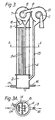
- Fig. 1 shows the construction and the mode of operation of a dynamic fluidized-bed reactor based on a horizontal cyclone as applied to combustion or, more generally, to carrying out a desired multi-component process.
- the process gas is passed into the reactor through the inlet opening 1 of the air chamber 2 placed in the bottom part of the reactor. Via the gas distributor plate 3 placed between the reactor chamber 5 and the air chamber 2, the gas is passed into the bottom part of the reactor chamber 5, into which the solid material separated in the horizontal separator is passed through the return pipe 9.
- the solid process material is fed into the reactor through the branch 12.
- the solid process product or waste is removed through the branch 13.
- the mantle 4 of the reactor chamber 5 may be cooled, and the reactor chamber may also have cooling elements.
- the gas containing solid matter is passed through the duct 8 tangentially to the circumference of the horizontal separator chamber 7 of the horizontal cyclone placed above the reactor chamber 5.
- the solid material separated out of the horizontal cyclone onto the wall is removed via a branch 6 placed on the circumference of the separator chamber, from which duct the solid material is passed further along the return pipe 9 to the desired location of the reactor.
- the gases purified in the horizontal cyclone are removed via both ends of the cyclone through the openings 10.
- the exhaust gas branches 11 can be connected to the branches 10 tangentially, whereby some of the tangential velocity of the exhaust gas can be recovered.
- Fig. 2 shows the construction of principle of a fire-tube boiler accomplished by means of a reactor of the sort shown in Fig. 1.
- the combustion air is passed from the air chamber 1 via the air distribution plate 2 into the combustion chamber 4, into whose bottom part the fuel is fed through the branch 3.
- the reactor in accordance with the invention operating in accordance with the principles indicated in the description of Fig. 1, is completely placed in a water space 12 and is, thus, fully cooled.
- the exhaust gas ducts 6 of the horizontal separator pass the gases purified of solid matter into the lower reversing chamber 8.
- the gases are cooled further and pass into the upper reversing chamber 10, and from there further through the pipes 11 into the system of flue gas ducts.
- the solid material is returned through the pipe 7 to an appropriate level in the combustion chamber 4.
- the branches 13 and 14 are the inlet and outlet ducts for the cooling water.
- Fig. 3 shows the reactor solution in accordance with the invention as applied to the purification of hot gases and to the recovery of heat, accomplished by means of two flow-through cyclones connected in series.
- the hot gases to be purified are passed into the reactor through the opening 1.
- a mixing chamber 2 into which the solid material is returned through the return pipes 4 and 13, and into which the necessary solid process material, if any, is fed (e.g., CaC0 3 for the absorption of sulphur oxides) through the branch 17.
- process material or waste e.g., CaS0 4
- the solid materials and the gas rise through the pipes 3 into the collecting space 5.
- the gases containing solids are passed tangentially to the circumference 7 of the first horizontal cyclone.
- the pre-purified gases are removed out of the first separator through one end or both ends of the separator chamber through the openings 8.
- the separated solid matter is returned into the mixing part 2 through the pipe 4.
- the pre-purified gases are passed to the circumference of the separator chamber 10 of the second horizontal separator.
- the pure gases are removed through the ends of the second horizontal separator through the openings 11.
- the separated solid matter is returned through the discharge pipe 13 into the mixing part 2.
- the gas ducts 9 and 12 are attached to the discharge openings 8 and 11 tangentially. The cooling of the reactor part in Fig.
- the tubes 3 and 4 are located in a water space 15 formed by the mantle 14.
- the gases are removed symmetrically, and the ends of the separator chamber are conical. It is clear that the ends of the separator chamber may also be plane and that the gas may also be removed from one side only. If necessary, the discharge pipes 10 of the horizontal separator may also extend into the separator chamber 7.
- a practical connection between the reactor chamber and the horizontal separator is shown, but it is clear that the separator may be located, e.g., eccentrically relative the reactor chamber and that the return duct for the solid matter may also be located outside the reactor chamber.
- the cooling part of the embodiment shown in Fig. 3 consists of fire tubes placed inside the mantle. It is obvious that the cooling may also be accomplished by means of water tube constructions. It is also evident that, if necessary, even more than two separators may be connected in series and/or in parallel.
Landscapes
- Engineering & Computer Science (AREA)
- Chemical & Material Sciences (AREA)
- Combustion & Propulsion (AREA)
- Mechanical Engineering (AREA)
- General Engineering & Computer Science (AREA)
- Physics & Mathematics (AREA)
- Thermal Sciences (AREA)
- Chemical Kinetics & Catalysis (AREA)
- Organic Chemistry (AREA)
- Cyclones (AREA)
- Transition And Organic Metals Composition Catalysts For Addition Polymerization (AREA)
- Devices And Processes Conducted In The Presence Of Fluids And Solid Particles (AREA)
- Organic Low-Molecular-Weight Compounds And Preparation Thereof (AREA)
- Fluidized-Bed Combustion And Resonant Combustion (AREA)
- Physical Or Chemical Processes And Apparatus (AREA)
- Steroid Compounds (AREA)
Abstract
Description
- The present invention relates to a dynamic fluidized-bed reactor in which solid particles are carried pneumatically through a reactor chamber and which includes a fluidized-bed part, a cyclone particle separator for purifying the gases from the fluidized-bed, and a return pipe connected to the separator chamber of the cyclone for returning separated particle material.
- The reactor is used for carrying out chemical or physical two- or multi-component processes. The main components of the reactor are feeder devices for gaseous and/or solid materials, the reactor chamber and the separator for solid or liquid materials.
- The main field of application of fluidized-bed reactors has been the production of energy from solid fuels. The burning takes place in a solids-gas suspension, the function of the solid and usually non-reactive material being the stabilizing of the combustion process. Fluidized-bed reactors are divided into two main groups according to their mode of operation:
- (1) static reactors, in which there is little carriage of solid particles along with the carrier gas, and
- (2) dynamic reactors, in which the solid particles are carried pneumatically through the reactor.
- In practical applications use is made of some features that are common to both static and dynamic reactors. Advantages of dynamic fluidized-bed reactors over static reactors include, for example, that of higher cross-sectional area heat-release characteristic and, maybe most important, that of better mixing of gaseous compounds. A drawback of dynamic fluidized-bed reactors is the absolute necessity of a solids separator. In spite of this drawback, there is a growing tendency to use dynamic fluidized-bed reactors in fluidized-bed technology.
- In dynamic fluidized-bed reactors a conventional cyclone having a solids return duct provided with a gas lock is used almost exclusively as the solids separator. The function of the gas lock is to prevent the flow of gas out of the reactor along the solids return duct into the cyclone. Such a gas flow would have a detrimental effect on the separating capacity of the cyclone.
- The document GB-A-2 104 408 discusses the drawbacks of conventional cyclone separators and mentions the disadvantages of positioning conventional cyclones inside the reactor. A reactor of the type initially mentioned is described, in which the gases flow tangentially through a pipe from the upper part of the reactor chamber to a vertical flow-through cyclone separator and are discharged through a separator discharge pipe passing through the bottom of the separator. The bottom of the cylindrical vortex chamber of the separator is substantially plane and is inclined, preferably towards the reactor. The separator solids flow through the return pipe to the lower part of the reactor chamber. This reactor has an advantageous recirculation system making use of a natural circulation of solid matter and avoids the need of a separate gas lock, but also has some operational and constructional drawbacks, as discussed below.
- Solid matter is collected on the bottom of the particle separator in an amount depending upon the loading of the reactor. A gas removing pipe is indispensable for the operation of the separator in order to prevent mixing of the solid matter flowing onto the bottom of the cyclone with the clean gas. For high temperatures the pipe must be made of a ceramic material and is therefore expensive, massive and of problematic construction. Moreover the pipe presents a substantial obstacle to the access of the solid matter, gathered on the bottom of the separator, into the discharge pipe. In practice, the surface of the circulating material in the bottom part of the flow-through cyclone tends to adopt a position and shape depending upon the material and the loading. This position and shape is, as a rule, unfavourable to the flow pattern of the cyclone. In order that a good separating ratio be achieved, a part of the volume of the cyclone is needed between the gas removing pipe and the cyclone chamber exclusively for storage of the gathered solid matter.
- The document US-A-3 698 874 describes a system for reducing dust emission to the atmosphere from a static fluidized-bed reactor. The system employs one or more vertical cyclone separators positioned inside the reactor, each separator being provided with a dip-leg extending into the bed for returning separated particles. One of the separators is provided with means for bypassing a small part of the gas stream to a filtering system that reduces dust emission by subjecting part of the gas stream carrying non- separable particles as an underflow stream to a filtering operation while returning separated fines to the fluid bed. Separator systems of this type are of disadvantage when used inside a dynamic fluidized-bed reactor.
- The documents DE-A-1 442 745 and FR-A-1 325 323 describe horizontal cyclones that are used by themselves as reactors in which fine solid materials are reacted with gases or liquids in order to bring about an exchange of material and/or heat.
- It is the object of the present invention to provide a reactor of the kind mentioned in the preamble of patent claim 1 wherein the reactor is of simplified construction and smaller size, yet permits a stable operation of the cyclone separator.
- This object is achieved by the cyclone separator being a horizontal cyclone fitted in the reactor chamber, the return pipe being connected to the circumference of the separator chamber, and the purified gases being removed through one end of the separator chamber.
- The multi-component reactor in accordance with the present invention makes it possible to eliminate the problems and drawbacks of fluidized-bed reactors that use conventional vertical flow-through cyclones.
- The most important advantages provided by the present invention are the constructional simplifications of the reactor and the operational improvements. Use of a horizontal cyclone makes it possible to avoid the operational and constructional drawbacks resulting from the storage of solid matter in flow-through cyclones. The use of a horizontal cyclone, permitting the reactor to be of simplified construction and smaller size, yields economies of investment. The horizontal separator operates even more stably than a flow-through cyclone, because the removal of the solid matter is made from the circumference of the separator chamber. The location of the solids removing pipe provides an increase in carrying capacity of the discharge pipe, because the solid matter arriving at the discharge pipe has a high velocity (mass flow=cross-sectional areaxvelocityxdensity). Owing to their stated properties, horizontal cyclones are particularly well suited for connection in series.
- The reactor of the present invention, using a horizontal cyclone, is particularly suitable for being provided with a fully cooled reactor part of a fire-tube boiler, because the shapes of the reactor, the separator and the gas and return pipes are favourable in view of heat expansion.
- Examples and embodiments of the invention are described in detail below with reference to the drawings in which
- Fig. 1 is a vertical sectional view of a reactor according to the present invention as used for combustion under complete or partial oxygenation;
- Fig. 1A is a plan view of the cyclone separator of the reactor shown in Fig. 1;
- Fig. 2 is a vertical sectional view of a reactor according to the present invention used as a part of a fire-tube boiler;
- Fig. 2A is a plan view of a cross-section along the line A-A of Fig. 2, seen in direction of the arrows;
- Fig. 3 is a vertical sectional view of a reactor according to the present invention as used for the cooling, heat recovery and purification of hot gases possibly containing gaseous and/or molten and vaporous and/or solid impurities; and
- Fig. 3A is a plan view of a cross-section along the line A-A of Fig. 3, seen in direction of the arrows.
- Fig. 1 shows the construction and the mode of operation of a dynamic fluidized-bed reactor based on a horizontal cyclone as applied to combustion or, more generally, to carrying out a desired multi-component process. The process gas is passed into the reactor through the inlet opening 1 of the air chamber 2 placed in the bottom part of the reactor. Via the
gas distributor plate 3 placed between thereactor chamber 5 and the air chamber 2, the gas is passed into the bottom part of thereactor chamber 5, into which the solid material separated in the horizontal separator is passed through thereturn pipe 9. The solid process material is fed into the reactor through thebranch 12. The solid process product or waste is removed through thebranch 13. Themantle 4 of thereactor chamber 5 may be cooled, and the reactor chamber may also have cooling elements. The gas containing solid matter is passed through theduct 8 tangentially to the circumference of thehorizontal separator chamber 7 of the horizontal cyclone placed above thereactor chamber 5. The solid material separated out of the horizontal cyclone onto the wall is removed via a branch 6 placed on the circumference of the separator chamber, from which duct the solid material is passed further along thereturn pipe 9 to the desired location of the reactor. The gases purified in the horizontal cyclone are removed via both ends of the cyclone through theopenings 10. Theexhaust gas branches 11 can be connected to thebranches 10 tangentially, whereby some of the tangential velocity of the exhaust gas can be recovered. - Fig. 2 shows the construction of principle of a fire-tube boiler accomplished by means of a reactor of the sort shown in Fig. 1. The combustion air is passed from the air chamber 1 via the air distribution plate 2 into the
combustion chamber 4, into whose bottom part the fuel is fed through thebranch 3. The reactor in accordance with the invention, operating in accordance with the principles indicated in the description of Fig. 1, is completely placed in awater space 12 and is, thus, fully cooled. The exhaust gas ducts 6 of the horizontal separator pass the gases purified of solid matter into the lower reversingchamber 8. In thefire tubes 9, the gases are cooled further and pass into the upper reversingchamber 10, and from there further through thepipes 11 into the system of flue gas ducts. The solid material is returned through thepipe 7 to an appropriate level in thecombustion chamber 4. Thebranches - Fig. 3 shows the reactor solution in accordance with the invention as applied to the purification of hot gases and to the recovery of heat, accomplished by means of two flow-through cyclones connected in series. The hot gases to be purified are passed into the reactor through the opening 1. In the bottom part of the reactor space, there is a mixing chamber 2, into which the solid material is returned through the
return pipes branch 16. The solid materials and the gas rise through thepipes 3 into the collectingspace 5. Through the branch 6, the gases containing solids are passed tangentially to thecircumference 7 of the first horizontal cyclone. The pre-purified gases are removed out of the first separator through one end or both ends of the separator chamber through theopenings 8. The separated solid matter is returned into the mixing part 2 through thepipe 4. Through thebranch 9, the pre-purified gases are passed to the circumference of theseparator chamber 10 of the second horizontal separator. The pure gases are removed through the ends of the second horizontal separator through theopenings 11. The separated solid matter is returned through thedischarge pipe 13 into the mixing part 2. In order to reduce losses of pressure, thegas ducts discharge openings tubes water space 15 formed by themantle 14. From the horizontal separator shown in Fig. 1, the gases are removed symmetrically, and the ends of the separator chamber are conical. It is clear that the ends of the separator chamber may also be plane and that the gas may also be removed from one side only. If necessary, thedischarge pipes 10 of the horizontal separator may also extend into theseparator chamber 7. In Fig. 1, a practical connection between the reactor chamber and the horizontal separator is shown, but it is clear that the separator may be located, e.g., eccentrically relative the reactor chamber and that the return duct for the solid matter may also be located outside the reactor chamber. - The cooling part of the embodiment shown in Fig. 3 consists of fire tubes placed inside the mantle. It is obvious that the cooling may also be accomplished by means of water tube constructions. It is also evident that, if necessary, even more than two separators may be connected in series and/or in parallel.
- Even otherwise, it should be stated that, above, the reactor invention has been described just in the tight of three exemplifying embodiments. This is, however, not supposed to confine the field of application of the invention concerned to the given example cases only.
Claims (7)
characterized in that the cyclone particle separator is a horizontal cyclone fitted in the reactor chamber that the return pipe is connected to the circumference of the separator chamber, and that the purified gases are removed through one end of the separator chamber.
Priority Applications (1)
| Application Number | Priority Date | Filing Date | Title |
|---|---|---|---|
| AT85901452T ATE44132T1 (en) | 1984-03-20 | 1985-03-20 | DOUBLE OR MULTIPLE REACTOR. |
Applications Claiming Priority (2)
| Application Number | Priority Date | Filing Date | Title |
|---|---|---|---|
| FI841126A FI70377B (en) | 1984-03-20 | 1984-03-20 | TVAO-ELLER FLERKOMPONENTREAKTOR |
| FI841126 | 1984-03-20 |
Publications (2)
| Publication Number | Publication Date |
|---|---|
| EP0177527A1 EP0177527A1 (en) | 1986-04-16 |
| EP0177527B1 true EP0177527B1 (en) | 1989-06-21 |
Family
ID=8518768
Family Applications (1)
| Application Number | Title | Priority Date | Filing Date |
|---|---|---|---|
| EP85901452A Expired EP0177527B1 (en) | 1984-03-20 | 1985-03-20 | Two- or multi-component reactor |
Country Status (11)
| Country | Link |
|---|---|
| EP (1) | EP0177527B1 (en) |
| JP (1) | JPS61501498A (en) |
| KR (1) | KR890001277B1 (en) |
| AT (1) | ATE44132T1 (en) |
| AU (1) | AU568201B2 (en) |
| DE (2) | DE177527T1 (en) |
| DK (1) | DK162142C (en) |
| FI (1) | FI70377B (en) |
| NO (1) | NO162948C (en) |
| SU (1) | SU1658812A3 (en) |
| WO (1) | WO1985004117A1 (en) |
Families Citing this family (12)
| Publication number | Priority date | Publication date | Assignee | Title |
|---|---|---|---|---|
| US4900516A (en) * | 1984-06-01 | 1990-02-13 | A. Ahlstrom Corporation | Fluidized bed reactor |
| FI850372A0 (en) * | 1985-01-29 | 1985-01-29 | Ahlstroem Oy | PANNA MED CIRKULERANDE BAEDD. |
| GB8526540D0 (en) * | 1985-10-28 | 1985-12-04 | Shell Int Research | Solids-fluid separation |
| EP0311599B1 (en) * | 1985-12-09 | 1990-11-07 | A. Ahlstrom Corporation | A circulating fluidized bed reactor and a method of separating solid material from the flue gases |
| FI85184C (en) * | 1986-05-19 | 1992-03-10 | Ahlstroem Oy | VIRVELBAEDDSREAKTOR. |
| FR2615600B1 (en) * | 1987-05-22 | 1990-04-20 | Mediterranee Const Navales Ind | PROCESS FOR PRODUCING A HOT AND BOILER FLUID FOR CARRYING OUT THIS PROCESS |
| US5174799A (en) * | 1990-04-06 | 1992-12-29 | Foster Wheeler Energy Corporation | Horizontal cyclone separator for a fluidized bed reactor |
| US5218931A (en) * | 1991-11-15 | 1993-06-15 | Foster Wheeler Energy Corporation | Fluidized bed steam reactor including two horizontal cyclone separators and an integral recycle heat exchanger |
| DE4308103A1 (en) * | 1993-03-15 | 1994-09-22 | Buehler Ag | Fluidized bed |
| FR2758277B1 (en) * | 1997-01-13 | 1999-10-08 | Inst Francais Du Petrole | SEPARATOR WITH DIRECT WINDING OF PARTICLES OF A GASEOUS MIXTURE AND ITS USE IN THERMAL OR CATALYTIC CRACKING IN A FLUIDIZED BED |
| CN102537943B (en) * | 2012-01-17 | 2014-04-02 | 清华大学 | Horizontal type circulating fluidized bed boiler with horizontal cyclone separator |
| CN107940449A (en) * | 2017-12-20 | 2018-04-20 | 眉山市鸿宇纸业有限公司 | A kind of boiler smoke folded angle separator |
Family Cites Families (4)
| Publication number | Priority date | Publication date | Assignee | Title |
|---|---|---|---|---|
| FR1325323A (en) * | 1962-06-07 | 1963-04-26 | Prep Ind Combustibles | fluid-solid reactor exchanger |
| DE1442745A1 (en) * | 1963-10-23 | 1969-02-06 | Kloeckner Humboldt Deutz Ag | Device for treating fine-grained, solid materials |
| US3698874A (en) * | 1970-07-23 | 1972-10-17 | Frederick A Zenz | Dust control apparatus for fluidized bed reactors |
| JPS553008A (en) * | 1978-06-21 | 1980-01-10 | Toshiba Corp | Automatic transaction device |
-
1984
- 1984-03-20 FI FI841126A patent/FI70377B/en not_active Application Discontinuation
-
1985
- 1985-03-20 WO PCT/FI1985/000027 patent/WO1985004117A1/en not_active Ceased
- 1985-03-20 AU AU41142/85A patent/AU568201B2/en not_active Ceased
- 1985-03-20 AT AT85901452T patent/ATE44132T1/en not_active IP Right Cessation
- 1985-03-20 JP JP60501151A patent/JPS61501498A/en active Pending
- 1985-03-20 KR KR1019850700311A patent/KR890001277B1/en not_active Expired
- 1985-03-20 DE DE198585901452T patent/DE177527T1/en active Pending
- 1985-03-20 EP EP85901452A patent/EP0177527B1/en not_active Expired
- 1985-03-20 DE DE8585901452T patent/DE3571124D1/en not_active Expired
- 1985-11-19 SU SU853983645A patent/SU1658812A3/en active
- 1985-11-19 DK DK533285A patent/DK162142C/en not_active IP Right Cessation
- 1985-11-19 NO NO85854622A patent/NO162948C/en unknown
Also Published As
| Publication number | Publication date |
|---|---|
| FI841126L (en) | 1985-09-21 |
| ATE44132T1 (en) | 1989-07-15 |
| WO1985004117A1 (en) | 1985-09-26 |
| SU1658812A3 (en) | 1991-06-23 |
| KR850700219A (en) | 1985-12-26 |
| EP0177527A1 (en) | 1986-04-16 |
| AU568201B2 (en) | 1987-12-17 |
| FI70377B (en) | 1986-03-27 |
| NO854622L (en) | 1985-11-19 |
| NO162948C (en) | 1990-03-14 |
| KR890001277B1 (en) | 1989-04-28 |
| FI841126A0 (en) | 1984-03-20 |
| DK162142B (en) | 1991-09-23 |
| DK533285D0 (en) | 1985-11-19 |
| AU4114285A (en) | 1985-10-11 |
| JPS61501498A (en) | 1986-07-24 |
| DE3571124D1 (en) | 1989-07-27 |
| DK533285A (en) | 1985-11-19 |
| DK162142C (en) | 1992-02-24 |
| DE177527T1 (en) | 1987-02-26 |
| NO162948B (en) | 1989-12-04 |
Similar Documents
| Publication | Publication Date | Title |
|---|---|---|
| CA1076796A (en) | Method of carrying out exothermic processes | |
| US5645620A (en) | System for separating particulates and condensable species from a gas stream | |
| US5205350A (en) | Process for cooling a hot process gas | |
| KR870000411A (en) | Fluidized bed reactor and its operation method | |
| KR910000672B1 (en) | Fluidized Bed Combustor with Integral Solid Separator | |
| CA1295191C (en) | Circulating fluidized bed reactor utilizing integral curved arm separators | |
| AU568201B2 (en) | Two-or multi-component reactor | |
| EP0630684B1 (en) | Method and apparatus for treating or utilizing a hot gas flow | |
| US5342594A (en) | Fluidized bed process for SOx removal | |
| US4664887A (en) | Apparatus for separating solid material in a circulating fluidized bed reactor | |
| US4755134A (en) | Circulating fluidized bed reactor | |
| US4867948A (en) | Fluidized bed reactor | |
| CA1265660A (en) | Circulating fluidized bed reactor and a method of separating solid material from the flue gases | |
| JP2969369B2 (en) | Combustion devices, especially swirl-bed combustion devices | |
| EP0165668B1 (en) | Heat exchanger | |
| US5372096A (en) | Internal particle collecting cells for circulating fluid bed combustion | |
| EP0700728B1 (en) | Fluidized bed reactor | |
| RU2125612C1 (en) | Method of reduction of oxide-containing material in the form of particles and plant for its embodiment | |
| US4900516A (en) | Fluidized bed reactor | |
| US5277151A (en) | Integral water-cooled circulating fluidized bed boiler system | |
| CA1258037A (en) | Apparatus for separating solids in a circulating fluidized bed reactor | |
| US5391211A (en) | Integral cylindrical cyclone and loopseal | |
| US4316729A (en) | Highly efficient cyclone separator | |
| US4874584A (en) | Fluidized bed reactor | |
| KR910001926B1 (en) | Circulating fluidized bed reactor |
Legal Events
| Date | Code | Title | Description |
|---|---|---|---|
| PUAI | Public reference made under article 153(3) epc to a published international application that has entered the european phase |
Free format text: ORIGINAL CODE: 0009012 |
|
| 17P | Request for examination filed |
Effective date: 19860206 |
|
| AK | Designated contracting states |
Kind code of ref document: A1 Designated state(s): AT DE FR GB SE |
|
| TCAT | At: translation of patent claims filed | ||
| EL | Fr: translation of claims filed | ||
| DET | De: translation of patent claims | ||
| 17Q | First examination report despatched |
Effective date: 19870615 |
|
| RAP1 | Party data changed (applicant data changed or rights of an application transferred) |
Owner name: A. AHLSTROEM CORPORATION |
|
| GRAA | (expected) grant |
Free format text: ORIGINAL CODE: 0009210 |
|
| AK | Designated contracting states |
Kind code of ref document: B1 Designated state(s): AT DE FR GB SE |
|
| REF | Corresponds to: |
Ref document number: 44132 Country of ref document: AT Date of ref document: 19890715 Kind code of ref document: T |
|
| REF | Corresponds to: |
Ref document number: 3571124 Country of ref document: DE Date of ref document: 19890727 |
|
| ET | Fr: translation filed | ||
| PLBE | No opposition filed within time limit |
Free format text: ORIGINAL CODE: 0009261 |
|
| STAA | Information on the status of an ep patent application or granted ep patent |
Free format text: STATUS: NO OPPOSITION FILED WITHIN TIME LIMIT |
|
| 26N | No opposition filed | ||
| PGFP | Annual fee paid to national office [announced via postgrant information from national office to epo] |
Ref country code: FR Payment date: 19940209 Year of fee payment: 10 |
|
| PGFP | Annual fee paid to national office [announced via postgrant information from national office to epo] |
Ref country code: AT Payment date: 19940214 Year of fee payment: 10 |
|
| PGFP | Annual fee paid to national office [announced via postgrant information from national office to epo] |
Ref country code: SE Payment date: 19940216 Year of fee payment: 10 Ref country code: GB Payment date: 19940216 Year of fee payment: 10 |
|
| PGFP | Annual fee paid to national office [announced via postgrant information from national office to epo] |
Ref country code: DE Payment date: 19940217 Year of fee payment: 10 |
|
| EAL | Se: european patent in force in sweden |
Ref document number: 85901452.4 |
|
| PG25 | Lapsed in a contracting state [announced via postgrant information from national office to epo] |
Ref country code: GB Effective date: 19950320 Ref country code: AT Effective date: 19950320 |
|
| PG25 | Lapsed in a contracting state [announced via postgrant information from national office to epo] |
Ref country code: SE Effective date: 19950321 |
|
| GBPC | Gb: european patent ceased through non-payment of renewal fee |
Effective date: 19950320 |
|
| PG25 | Lapsed in a contracting state [announced via postgrant information from national office to epo] |
Ref country code: FR Free format text: LAPSE BECAUSE OF NON-PAYMENT OF DUE FEES Effective date: 19951130 |
|
| PG25 | Lapsed in a contracting state [announced via postgrant information from national office to epo] |
Ref country code: DE Effective date: 19951201 |
|
| EUG | Se: european patent has lapsed |
Ref document number: 85901452.4 |
|
| REG | Reference to a national code |
Ref country code: FR Ref legal event code: ST |