EP0177470A2 - A tube and a method and a device for manufacturing of the tube - Google Patents
A tube and a method and a device for manufacturing of the tube Download PDFInfo
- Publication number
- EP0177470A2 EP0177470A2 EP85850292A EP85850292A EP0177470A2 EP 0177470 A2 EP0177470 A2 EP 0177470A2 EP 85850292 A EP85850292 A EP 85850292A EP 85850292 A EP85850292 A EP 85850292A EP 0177470 A2 EP0177470 A2 EP 0177470A2
- Authority
- EP
- European Patent Office
- Prior art keywords
- tube
- strip
- metal foil
- tube body
- mandrel
- Prior art date
- Legal status (The legal status is an assumption and is not a legal conclusion. Google has not performed a legal analysis and makes no representation as to the accuracy of the status listed.)
- Granted
Links
Images

Classifications
-
- B—PERFORMING OPERATIONS; TRANSPORTING
- B29—WORKING OF PLASTICS; WORKING OF SUBSTANCES IN A PLASTIC STATE IN GENERAL
- B29C—SHAPING OR JOINING OF PLASTICS; SHAPING OF MATERIAL IN A PLASTIC STATE, NOT OTHERWISE PROVIDED FOR; AFTER-TREATMENT OF THE SHAPED PRODUCTS, e.g. REPAIRING
- B29C66/00—General aspects of processes or apparatus for joining preformed parts
- B29C66/70—General aspects of processes or apparatus for joining preformed parts characterised by the composition, physical properties or the structure of the material of the parts to be joined; Joining with non-plastics material
- B29C66/72—General aspects of processes or apparatus for joining preformed parts characterised by the composition, physical properties or the structure of the material of the parts to be joined; Joining with non-plastics material characterised by the structure of the material of the parts to be joined
- B29C66/723—General aspects of processes or apparatus for joining preformed parts characterised by the composition, physical properties or the structure of the material of the parts to be joined; Joining with non-plastics material characterised by the structure of the material of the parts to be joined being multi-layered
- B29C66/7232—General aspects of processes or apparatus for joining preformed parts characterised by the composition, physical properties or the structure of the material of the parts to be joined; Joining with non-plastics material characterised by the structure of the material of the parts to be joined being multi-layered comprising a non-plastics layer
- B29C66/72321—General aspects of processes or apparatus for joining preformed parts characterised by the composition, physical properties or the structure of the material of the parts to be joined; Joining with non-plastics material characterised by the structure of the material of the parts to be joined being multi-layered comprising a non-plastics layer consisting of metals or their alloys
-
- B—PERFORMING OPERATIONS; TRANSPORTING
- B29—WORKING OF PLASTICS; WORKING OF SUBSTANCES IN A PLASTIC STATE IN GENERAL
- B29C—SHAPING OR JOINING OF PLASTICS; SHAPING OF MATERIAL IN A PLASTIC STATE, NOT OTHERWISE PROVIDED FOR; AFTER-TREATMENT OF THE SHAPED PRODUCTS, e.g. REPAIRING
- B29C53/00—Shaping by bending, folding, twisting, straightening or flattening; Apparatus therefor
- B29C53/36—Bending and joining, e.g. for making hollow articles
- B29C53/38—Bending and joining, e.g. for making hollow articles by bending sheets or strips at right angles to the longitudinal axis of the article being formed and joining the edges
- B29C53/382—Bending and joining, e.g. for making hollow articles by bending sheets or strips at right angles to the longitudinal axis of the article being formed and joining the edges using laminated sheets
-
- B—PERFORMING OPERATIONS; TRANSPORTING
- B29—WORKING OF PLASTICS; WORKING OF SUBSTANCES IN A PLASTIC STATE IN GENERAL
- B29C—SHAPING OR JOINING OF PLASTICS; SHAPING OF MATERIAL IN A PLASTIC STATE, NOT OTHERWISE PROVIDED FOR; AFTER-TREATMENT OF THE SHAPED PRODUCTS, e.g. REPAIRING
- B29C53/00—Shaping by bending, folding, twisting, straightening or flattening; Apparatus therefor
- B29C53/36—Bending and joining, e.g. for making hollow articles
- B29C53/38—Bending and joining, e.g. for making hollow articles by bending sheets or strips at right angles to the longitudinal axis of the article being formed and joining the edges
- B29C53/48—Bending and joining, e.g. for making hollow articles by bending sheets or strips at right angles to the longitudinal axis of the article being formed and joining the edges for articles of indefinite length, i.e. bending a strip progressively
- B29C53/50—Bending and joining, e.g. for making hollow articles by bending sheets or strips at right angles to the longitudinal axis of the article being formed and joining the edges for articles of indefinite length, i.e. bending a strip progressively using internal forming surfaces, e.g. mandrels
-
- B—PERFORMING OPERATIONS; TRANSPORTING
- B29—WORKING OF PLASTICS; WORKING OF SUBSTANCES IN A PLASTIC STATE IN GENERAL
- B29C—SHAPING OR JOINING OF PLASTICS; SHAPING OF MATERIAL IN A PLASTIC STATE, NOT OTHERWISE PROVIDED FOR; AFTER-TREATMENT OF THE SHAPED PRODUCTS, e.g. REPAIRING
- B29C65/00—Joining or sealing of preformed parts, e.g. welding of plastics materials; Apparatus therefor
- B29C65/02—Joining or sealing of preformed parts, e.g. welding of plastics materials; Apparatus therefor by heating, with or without pressure
- B29C65/34—Joining or sealing of preformed parts, e.g. welding of plastics materials; Apparatus therefor by heating, with or without pressure using heated elements which remain in the joint, e.g. "verlorenes Schweisselement"
- B29C65/36—Joining or sealing of preformed parts, e.g. welding of plastics materials; Apparatus therefor by heating, with or without pressure using heated elements which remain in the joint, e.g. "verlorenes Schweisselement" heated by induction
- B29C65/3604—Joining or sealing of preformed parts, e.g. welding of plastics materials; Apparatus therefor by heating, with or without pressure using heated elements which remain in the joint, e.g. "verlorenes Schweisselement" heated by induction characterised by the type of elements heated by induction which remain in the joint
- B29C65/3644—Joining or sealing of preformed parts, e.g. welding of plastics materials; Apparatus therefor by heating, with or without pressure using heated elements which remain in the joint, e.g. "verlorenes Schweisselement" heated by induction characterised by the type of elements heated by induction which remain in the joint being a ribbon, band or strip
-
- B—PERFORMING OPERATIONS; TRANSPORTING
- B29—WORKING OF PLASTICS; WORKING OF SUBSTANCES IN A PLASTIC STATE IN GENERAL
- B29C—SHAPING OR JOINING OF PLASTICS; SHAPING OF MATERIAL IN A PLASTIC STATE, NOT OTHERWISE PROVIDED FOR; AFTER-TREATMENT OF THE SHAPED PRODUCTS, e.g. REPAIRING
- B29C65/00—Joining or sealing of preformed parts, e.g. welding of plastics materials; Apparatus therefor
- B29C65/02—Joining or sealing of preformed parts, e.g. welding of plastics materials; Apparatus therefor by heating, with or without pressure
- B29C65/34—Joining or sealing of preformed parts, e.g. welding of plastics materials; Apparatus therefor by heating, with or without pressure using heated elements which remain in the joint, e.g. "verlorenes Schweisselement"
- B29C65/36—Joining or sealing of preformed parts, e.g. welding of plastics materials; Apparatus therefor by heating, with or without pressure using heated elements which remain in the joint, e.g. "verlorenes Schweisselement" heated by induction
- B29C65/3604—Joining or sealing of preformed parts, e.g. welding of plastics materials; Apparatus therefor by heating, with or without pressure using heated elements which remain in the joint, e.g. "verlorenes Schweisselement" heated by induction characterised by the type of elements heated by induction which remain in the joint
- B29C65/3656—Joining or sealing of preformed parts, e.g. welding of plastics materials; Apparatus therefor by heating, with or without pressure using heated elements which remain in the joint, e.g. "verlorenes Schweisselement" heated by induction characterised by the type of elements heated by induction which remain in the joint being a layer of a multilayer part to be joined, e.g. for joining plastic-metal laminates
-
- B—PERFORMING OPERATIONS; TRANSPORTING
- B29—WORKING OF PLASTICS; WORKING OF SUBSTANCES IN A PLASTIC STATE IN GENERAL
- B29C—SHAPING OR JOINING OF PLASTICS; SHAPING OF MATERIAL IN A PLASTIC STATE, NOT OTHERWISE PROVIDED FOR; AFTER-TREATMENT OF THE SHAPED PRODUCTS, e.g. REPAIRING
- B29C65/00—Joining or sealing of preformed parts, e.g. welding of plastics materials; Apparatus therefor
- B29C65/02—Joining or sealing of preformed parts, e.g. welding of plastics materials; Apparatus therefor by heating, with or without pressure
- B29C65/34—Joining or sealing of preformed parts, e.g. welding of plastics materials; Apparatus therefor by heating, with or without pressure using heated elements which remain in the joint, e.g. "verlorenes Schweisselement"
- B29C65/36—Joining or sealing of preformed parts, e.g. welding of plastics materials; Apparatus therefor by heating, with or without pressure using heated elements which remain in the joint, e.g. "verlorenes Schweisselement" heated by induction
- B29C65/3672—Joining or sealing of preformed parts, e.g. welding of plastics materials; Apparatus therefor by heating, with or without pressure using heated elements which remain in the joint, e.g. "verlorenes Schweisselement" heated by induction characterised by the composition of the elements heated by induction which remain in the joint
- B29C65/3676—Joining or sealing of preformed parts, e.g. welding of plastics materials; Apparatus therefor by heating, with or without pressure using heated elements which remain in the joint, e.g. "verlorenes Schweisselement" heated by induction characterised by the composition of the elements heated by induction which remain in the joint being metallic
- B29C65/368—Joining or sealing of preformed parts, e.g. welding of plastics materials; Apparatus therefor by heating, with or without pressure using heated elements which remain in the joint, e.g. "verlorenes Schweisselement" heated by induction characterised by the composition of the elements heated by induction which remain in the joint being metallic with a polymer coating
-
- B—PERFORMING OPERATIONS; TRANSPORTING
- B29—WORKING OF PLASTICS; WORKING OF SUBSTANCES IN A PLASTIC STATE IN GENERAL
- B29C—SHAPING OR JOINING OF PLASTICS; SHAPING OF MATERIAL IN A PLASTIC STATE, NOT OTHERWISE PROVIDED FOR; AFTER-TREATMENT OF THE SHAPED PRODUCTS, e.g. REPAIRING
- B29C65/00—Joining or sealing of preformed parts, e.g. welding of plastics materials; Apparatus therefor
- B29C65/48—Joining or sealing of preformed parts, e.g. welding of plastics materials; Apparatus therefor using adhesives, i.e. using supplementary joining material; solvent bonding
- B29C65/4805—Joining or sealing of preformed parts, e.g. welding of plastics materials; Apparatus therefor using adhesives, i.e. using supplementary joining material; solvent bonding characterised by the type of adhesives
- B29C65/481—Non-reactive adhesives, e.g. physically hardening adhesives
- B29C65/4815—Hot melt adhesives, e.g. thermoplastic adhesives
-
- B—PERFORMING OPERATIONS; TRANSPORTING
- B29—WORKING OF PLASTICS; WORKING OF SUBSTANCES IN A PLASTIC STATE IN GENERAL
- B29C—SHAPING OR JOINING OF PLASTICS; SHAPING OF MATERIAL IN A PLASTIC STATE, NOT OTHERWISE PROVIDED FOR; AFTER-TREATMENT OF THE SHAPED PRODUCTS, e.g. REPAIRING
- B29C65/00—Joining or sealing of preformed parts, e.g. welding of plastics materials; Apparatus therefor
- B29C65/48—Joining or sealing of preformed parts, e.g. welding of plastics materials; Apparatus therefor using adhesives, i.e. using supplementary joining material; solvent bonding
- B29C65/50—Joining or sealing of preformed parts, e.g. welding of plastics materials; Apparatus therefor using adhesives, i.e. using supplementary joining material; solvent bonding using adhesive tape, e.g. thermoplastic tape; using threads or the like
- B29C65/5007—Joining or sealing of preformed parts, e.g. welding of plastics materials; Apparatus therefor using adhesives, i.e. using supplementary joining material; solvent bonding using adhesive tape, e.g. thermoplastic tape; using threads or the like characterised by the structure of said adhesive tape, threads or the like
- B29C65/5021—Joining or sealing of preformed parts, e.g. welding of plastics materials; Apparatus therefor using adhesives, i.e. using supplementary joining material; solvent bonding using adhesive tape, e.g. thermoplastic tape; using threads or the like characterised by the structure of said adhesive tape, threads or the like being multi-layered
-
- B—PERFORMING OPERATIONS; TRANSPORTING
- B29—WORKING OF PLASTICS; WORKING OF SUBSTANCES IN A PLASTIC STATE IN GENERAL
- B29C—SHAPING OR JOINING OF PLASTICS; SHAPING OF MATERIAL IN A PLASTIC STATE, NOT OTHERWISE PROVIDED FOR; AFTER-TREATMENT OF THE SHAPED PRODUCTS, e.g. REPAIRING
- B29C65/00—Joining or sealing of preformed parts, e.g. welding of plastics materials; Apparatus therefor
- B29C65/48—Joining or sealing of preformed parts, e.g. welding of plastics materials; Apparatus therefor using adhesives, i.e. using supplementary joining material; solvent bonding
- B29C65/50—Joining or sealing of preformed parts, e.g. welding of plastics materials; Apparatus therefor using adhesives, i.e. using supplementary joining material; solvent bonding using adhesive tape, e.g. thermoplastic tape; using threads or the like
- B29C65/5042—Joining or sealing of preformed parts, e.g. welding of plastics materials; Apparatus therefor using adhesives, i.e. using supplementary joining material; solvent bonding using adhesive tape, e.g. thermoplastic tape; using threads or the like covering both elements to be joined
-
- B—PERFORMING OPERATIONS; TRANSPORTING
- B29—WORKING OF PLASTICS; WORKING OF SUBSTANCES IN A PLASTIC STATE IN GENERAL
- B29C—SHAPING OR JOINING OF PLASTICS; SHAPING OF MATERIAL IN A PLASTIC STATE, NOT OTHERWISE PROVIDED FOR; AFTER-TREATMENT OF THE SHAPED PRODUCTS, e.g. REPAIRING
- B29C66/00—General aspects of processes or apparatus for joining preformed parts
- B29C66/01—General aspects dealing with the joint area or with the area to be joined
- B29C66/03—After-treatments in the joint area
- B29C66/034—Thermal after-treatments
- B29C66/0342—Cooling, e.g. transporting through welding and cooling zone
-
- B—PERFORMING OPERATIONS; TRANSPORTING
- B29—WORKING OF PLASTICS; WORKING OF SUBSTANCES IN A PLASTIC STATE IN GENERAL
- B29C—SHAPING OR JOINING OF PLASTICS; SHAPING OF MATERIAL IN A PLASTIC STATE, NOT OTHERWISE PROVIDED FOR; AFTER-TREATMENT OF THE SHAPED PRODUCTS, e.g. REPAIRING
- B29C66/00—General aspects of processes or apparatus for joining preformed parts
- B29C66/01—General aspects dealing with the joint area or with the area to be joined
- B29C66/05—Particular design of joint configurations
- B29C66/10—Particular design of joint configurations particular design of the joint cross-sections
- B29C66/11—Joint cross-sections comprising a single joint-segment, i.e. one of the parts to be joined comprising a single joint-segment in the joint cross-section
- B29C66/114—Single butt joints
- B29C66/1142—Single butt to butt joints
-
- B—PERFORMING OPERATIONS; TRANSPORTING
- B29—WORKING OF PLASTICS; WORKING OF SUBSTANCES IN A PLASTIC STATE IN GENERAL
- B29C—SHAPING OR JOINING OF PLASTICS; SHAPING OF MATERIAL IN A PLASTIC STATE, NOT OTHERWISE PROVIDED FOR; AFTER-TREATMENT OF THE SHAPED PRODUCTS, e.g. REPAIRING
- B29C66/00—General aspects of processes or apparatus for joining preformed parts
- B29C66/40—General aspects of joining substantially flat articles, e.g. plates, sheets or web-like materials; Making flat seams in tubular or hollow articles; Joining single elements to substantially flat surfaces
- B29C66/41—Joining substantially flat articles ; Making flat seams in tubular or hollow articles
- B29C66/43—Joining a relatively small portion of the surface of said articles
- B29C66/432—Joining a relatively small portion of the surface of said articles for making tubular articles or closed loops, e.g. by joining several sheets ; for making hollow articles or hollow preforms
- B29C66/4322—Joining a relatively small portion of the surface of said articles for making tubular articles or closed loops, e.g. by joining several sheets ; for making hollow articles or hollow preforms by joining a single sheet to itself
-
- B—PERFORMING OPERATIONS; TRANSPORTING
- B29—WORKING OF PLASTICS; WORKING OF SUBSTANCES IN A PLASTIC STATE IN GENERAL
- B29C—SHAPING OR JOINING OF PLASTICS; SHAPING OF MATERIAL IN A PLASTIC STATE, NOT OTHERWISE PROVIDED FOR; AFTER-TREATMENT OF THE SHAPED PRODUCTS, e.g. REPAIRING
- B29C66/00—General aspects of processes or apparatus for joining preformed parts
- B29C66/40—General aspects of joining substantially flat articles, e.g. plates, sheets or web-like materials; Making flat seams in tubular or hollow articles; Joining single elements to substantially flat surfaces
- B29C66/49—Internally supporting the, e.g. tubular, article during joining
-
- B—PERFORMING OPERATIONS; TRANSPORTING
- B29—WORKING OF PLASTICS; WORKING OF SUBSTANCES IN A PLASTIC STATE IN GENERAL
- B29C—SHAPING OR JOINING OF PLASTICS; SHAPING OF MATERIAL IN A PLASTIC STATE, NOT OTHERWISE PROVIDED FOR; AFTER-TREATMENT OF THE SHAPED PRODUCTS, e.g. REPAIRING
- B29C66/00—General aspects of processes or apparatus for joining preformed parts
- B29C66/80—General aspects of machine operations or constructions and parts thereof
- B29C66/81—General aspects of the pressing elements, i.e. the elements applying pressure on the parts to be joined in the area to be joined, e.g. the welding jaws or clamps
- B29C66/818—General aspects of the pressing elements, i.e. the elements applying pressure on the parts to be joined in the area to be joined, e.g. the welding jaws or clamps characterised by the cooling constructional aspects, or by the thermal or electrical insulating or conducting constructional aspects of the welding jaws or of the clamps ; comprising means for compensating for the thermal expansion of the welding jaws or of the clamps
- B29C66/8181—General aspects of the pressing elements, i.e. the elements applying pressure on the parts to be joined in the area to be joined, e.g. the welding jaws or clamps characterised by the cooling constructional aspects, or by the thermal or electrical insulating or conducting constructional aspects of the welding jaws or of the clamps ; comprising means for compensating for the thermal expansion of the welding jaws or of the clamps characterised by the cooling constructional aspects
- B29C66/81811—General aspects of the pressing elements, i.e. the elements applying pressure on the parts to be joined in the area to be joined, e.g. the welding jaws or clamps characterised by the cooling constructional aspects, or by the thermal or electrical insulating or conducting constructional aspects of the welding jaws or of the clamps ; comprising means for compensating for the thermal expansion of the welding jaws or of the clamps characterised by the cooling constructional aspects of the welding jaws
-
- B—PERFORMING OPERATIONS; TRANSPORTING
- B29—WORKING OF PLASTICS; WORKING OF SUBSTANCES IN A PLASTIC STATE IN GENERAL
- B29C—SHAPING OR JOINING OF PLASTICS; SHAPING OF MATERIAL IN A PLASTIC STATE, NOT OTHERWISE PROVIDED FOR; AFTER-TREATMENT OF THE SHAPED PRODUCTS, e.g. REPAIRING
- B29C66/00—General aspects of processes or apparatus for joining preformed parts
- B29C66/80—General aspects of machine operations or constructions and parts thereof
- B29C66/83—General aspects of machine operations or constructions and parts thereof characterised by the movement of the joining or pressing tools
- B29C66/834—General aspects of machine operations or constructions and parts thereof characterised by the movement of the joining or pressing tools moving with the parts to be joined
- B29C66/8341—Roller, cylinder or drum types; Band or belt types; Ball types
- B29C66/83421—Roller, cylinder or drum types; Band or belt types; Ball types band or belt types
-
- B—PERFORMING OPERATIONS; TRANSPORTING
- B29—WORKING OF PLASTICS; WORKING OF SUBSTANCES IN A PLASTIC STATE IN GENERAL
- B29D—PRODUCING PARTICULAR ARTICLES FROM PLASTICS OR FROM SUBSTANCES IN A PLASTIC STATE
- B29D23/00—Producing tubular articles
- B29D23/20—Flexible squeeze tubes, e.g. for cosmetics
-
- B—PERFORMING OPERATIONS; TRANSPORTING
- B65—CONVEYING; PACKING; STORING; HANDLING THIN OR FILAMENTARY MATERIAL
- B65D—CONTAINERS FOR STORAGE OR TRANSPORT OF ARTICLES OR MATERIALS, e.g. BAGS, BARRELS, BOTTLES, BOXES, CANS, CARTONS, CRATES, DRUMS, JARS, TANKS, HOPPERS, FORWARDING CONTAINERS; ACCESSORIES, CLOSURES, OR FITTINGS THEREFOR; PACKAGING ELEMENTS; PACKAGES
- B65D35/00—Pliable tubular containers adapted to be permanently or temporarily deformed to expel contents, e.g. collapsible tubes for toothpaste or other plastic or semi-liquid material; Holders therefor
- B65D35/02—Body construction
-
- B—PERFORMING OPERATIONS; TRANSPORTING
- B29—WORKING OF PLASTICS; WORKING OF SUBSTANCES IN A PLASTIC STATE IN GENERAL
- B29C—SHAPING OR JOINING OF PLASTICS; SHAPING OF MATERIAL IN A PLASTIC STATE, NOT OTHERWISE PROVIDED FOR; AFTER-TREATMENT OF THE SHAPED PRODUCTS, e.g. REPAIRING
- B29C66/00—General aspects of processes or apparatus for joining preformed parts
- B29C66/01—General aspects dealing with the joint area or with the area to be joined
- B29C66/05—Particular design of joint configurations
- B29C66/10—Particular design of joint configurations particular design of the joint cross-sections
- B29C66/11—Joint cross-sections comprising a single joint-segment, i.e. one of the parts to be joined comprising a single joint-segment in the joint cross-section
- B29C66/112—Single lapped joints
- B29C66/1122—Single lap to lap joints, i.e. overlap joints
-
- B—PERFORMING OPERATIONS; TRANSPORTING
- B29—WORKING OF PLASTICS; WORKING OF SUBSTANCES IN A PLASTIC STATE IN GENERAL
- B29C—SHAPING OR JOINING OF PLASTICS; SHAPING OF MATERIAL IN A PLASTIC STATE, NOT OTHERWISE PROVIDED FOR; AFTER-TREATMENT OF THE SHAPED PRODUCTS, e.g. REPAIRING
- B29C66/00—General aspects of processes or apparatus for joining preformed parts
- B29C66/40—General aspects of joining substantially flat articles, e.g. plates, sheets or web-like materials; Making flat seams in tubular or hollow articles; Joining single elements to substantially flat surfaces
- B29C66/41—Joining substantially flat articles ; Making flat seams in tubular or hollow articles
- B29C66/43—Joining a relatively small portion of the surface of said articles
- B29C66/431—Joining the articles to themselves
- B29C66/4312—Joining the articles to themselves for making flat seams in tubular or hollow articles, e.g. transversal seams
- B29C66/43121—Closing the ends of tubular or hollow single articles, e.g. closing the ends of bags
- B29C66/43123—Closing the ends of squeeze tubes, e.g. for toothpaste or cosmetics
-
- B—PERFORMING OPERATIONS; TRANSPORTING
- B29—WORKING OF PLASTICS; WORKING OF SUBSTANCES IN A PLASTIC STATE IN GENERAL
- B29C—SHAPING OR JOINING OF PLASTICS; SHAPING OF MATERIAL IN A PLASTIC STATE, NOT OTHERWISE PROVIDED FOR; AFTER-TREATMENT OF THE SHAPED PRODUCTS, e.g. REPAIRING
- B29C66/00—General aspects of processes or apparatus for joining preformed parts
- B29C66/50—General aspects of joining tubular articles; General aspects of joining long products, i.e. bars or profiled elements; General aspects of joining single elements to tubular articles, hollow articles or bars; General aspects of joining several hollow-preforms to form hollow or tubular articles
- B29C66/51—Joining tubular articles, profiled elements or bars; Joining single elements to tubular articles, hollow articles or bars; Joining several hollow-preforms to form hollow or tubular articles
- B29C66/53—Joining single elements to tubular articles, hollow articles or bars
- B29C66/534—Joining single elements to open ends of tubular or hollow articles or to the ends of bars
- B29C66/5344—Joining single elements to open ends of tubular or hollow articles or to the ends of bars said single elements being substantially annular, i.e. of finite length, e.g. joining flanges to tube ends
-
- B—PERFORMING OPERATIONS; TRANSPORTING
- B29—WORKING OF PLASTICS; WORKING OF SUBSTANCES IN A PLASTIC STATE IN GENERAL
- B29C—SHAPING OR JOINING OF PLASTICS; SHAPING OF MATERIAL IN A PLASTIC STATE, NOT OTHERWISE PROVIDED FOR; AFTER-TREATMENT OF THE SHAPED PRODUCTS, e.g. REPAIRING
- B29C66/00—General aspects of processes or apparatus for joining preformed parts
- B29C66/70—General aspects of processes or apparatus for joining preformed parts characterised by the composition, physical properties or the structure of the material of the parts to be joined; Joining with non-plastics material
- B29C66/71—General aspects of processes or apparatus for joining preformed parts characterised by the composition, physical properties or the structure of the material of the parts to be joined; Joining with non-plastics material characterised by the composition of the plastics material of the parts to be joined
-
- B—PERFORMING OPERATIONS; TRANSPORTING
- B29—WORKING OF PLASTICS; WORKING OF SUBSTANCES IN A PLASTIC STATE IN GENERAL
- B29L—INDEXING SCHEME ASSOCIATED WITH SUBCLASS B29C, RELATING TO PARTICULAR ARTICLES
- B29L2009/00—Layered products
- B29L2009/003—Layered products comprising a metal layer
-
- B—PERFORMING OPERATIONS; TRANSPORTING
- B29—WORKING OF PLASTICS; WORKING OF SUBSTANCES IN A PLASTIC STATE IN GENERAL
- B29L—INDEXING SCHEME ASSOCIATED WITH SUBCLASS B29C, RELATING TO PARTICULAR ARTICLES
- B29L2023/00—Tubular articles
- B29L2023/20—Flexible squeeze tubes, e.g. for cosmetics
-
- Y—GENERAL TAGGING OF NEW TECHNOLOGICAL DEVELOPMENTS; GENERAL TAGGING OF CROSS-SECTIONAL TECHNOLOGIES SPANNING OVER SEVERAL SECTIONS OF THE IPC; TECHNICAL SUBJECTS COVERED BY FORMER USPC CROSS-REFERENCE ART COLLECTIONS [XRACs] AND DIGESTS
- Y10—TECHNICAL SUBJECTS COVERED BY FORMER USPC
- Y10T—TECHNICAL SUBJECTS COVERED BY FORMER US CLASSIFICATION
- Y10T156/00—Adhesive bonding and miscellaneous chemical manufacture
- Y10T156/10—Methods of surface bonding and/or assembly therefor
- Y10T156/1002—Methods of surface bonding and/or assembly therefor with permanent bending or reshaping or surface deformation of self sustaining lamina
- Y10T156/1007—Running or continuous length work
- Y10T156/1008—Longitudinal bending
- Y10T156/1013—Longitudinal bending and edge-joining of one piece blank to form tube
-
- Y—GENERAL TAGGING OF NEW TECHNOLOGICAL DEVELOPMENTS; GENERAL TAGGING OF CROSS-SECTIONAL TECHNOLOGIES SPANNING OVER SEVERAL SECTIONS OF THE IPC; TECHNICAL SUBJECTS COVERED BY FORMER USPC CROSS-REFERENCE ART COLLECTIONS [XRACs] AND DIGESTS
- Y10—TECHNICAL SUBJECTS COVERED BY FORMER USPC
- Y10T—TECHNICAL SUBJECTS COVERED BY FORMER US CLASSIFICATION
- Y10T428/00—Stock material or miscellaneous articles
- Y10T428/13—Hollow or container type article [e.g., tube, vase, etc.]
- Y10T428/1352—Polymer or resin containing [i.e., natural or synthetic]
- Y10T428/1355—Elemental metal containing [e.g., substrate, foil, film, coating, etc.]
- Y10T428/1359—Three or more layers [continuous layer]
Definitions
- the present invention relates to a packaging tube, more precisely a tube of the laminate tube type.
- the invention relates also to a method and a device for manufacturing of the actual tube.
- laminate tube means a tube manufactured from a laminate comprising metal foil, usually aluminium foil.
- Laminate tubes are well known. As time has passed by laminate materials as well as the manufacturing technique have been developed.
- a "dead” material in such cases, i.e. a material without a tendency of returning or without "a mechanical memory”.
- the term used within the actual technical field is a material having pronounced dead-fold characteristics.
- the term dead-fold falls under a broader term called "resilience" and frequently used when defining the overall characteristics of a metal foil containing laminate.
- the problem may be identified by recognizing the fact that a laminate tube is more like an all-plastics tube than a metal tube (for instance lead or zinc tube), unless specific measures are taken.
- the return tendency the laminate tube has, without such measures, for instance means that the contents of the tube will be exposed to a large volume of air when the tube returns to its original shape although the contents of the tube has decreased drastically.
- Double metal foils one at each side of a centre polymer layer, are used for a laminate having additional layers of plastic and binder.
- This tube structure means a high cost of material and a complex and expensive manufacturing method.
- the third method which is described in EP 0 084 922, makes use of a polymer layer having an organic additive as a filler.
- the layer having such filler forms the element providing dead-fold by forming grooves or other weakening lines in the layer for counter-acting a return tendency. From a barrier point of view this method involves a dangerous working of the material of the outer layer protecting the metal foil. There is a risk for damage of the metal foil. Additionally, the possibility of the important step of printing the tube will be negatively affected.
- a packaging tube comprising a body of a metal foil containing laminate, a tube breast having an discharge opening at one end of the body, and an elongated element attached to the tube body and extending generally along the entire length thereof.
- the tube is characterized in that the elongated element comprises a strip having dead-fold characteristics manufactured from a metal foil containing material, and that the thickness of the metal foil of the tube body falls within the interval 5 to 40 microns, and is selected such that the metal foil of the body is considerably thinner than the thickness of the metal foil of the strip which falls within the interval 40 to 200 microns
- the thickness relation preferably is such that a foil thickness of the tube body of for instance 5 microns corresponds to a strip thickness of 200 microns, i.e. a certain thickness taken from the lower region of the tube body interval corresponds to a certain thickness taken from the upper region of the strip interval.
- the strip is arranged on the inside of the tube body and has such a width that on both sides of a longitudinal tube body joint there is formed a barrier against penetration into the longitudinal joint of substances of the filling goods having delaminating characteristics.
- the heat sealing method is the most preferable method for longitudinal sealing of tubes, the side of the strip facing the inside of the tube body is provided with a layer of a polyolefine plastics of a type being heat sealing compatible with the inside of the tube body.
- the strip has a plastics layer of an over-dimensioned thickness before attaching the strip, such that the excess amount of plastics will "flow out” and cover the edges of the strip after it has been sealed by heat sealing.
- an external strip over the longitudinal joint.
- the plastics layer of the strip preferably is over-dimensioned and arranged such that it covers the edges of the strip after it has been heat sealed.
- the laminate of the tube body is arranged edge against edge.
- the metal foil containing tube body and the dead-fold strip are attached to an all-metal breast, for instance of aluminium.
- the tube body may be made conical.
- the tube body is made from a trapezoid blank.
- the invention also provides a method for manufacturing of a packaging tube, comprising a body of a metal foil containing laminate and a tube breast having a discharge opening at one end of the body, and an elongated element attached to the tube body such that it extends in the longitudinal direction of the body and generally along the entire length thereof.
- the method is characterized in that the elongated element is selected such that it comprises a strip of a metal foil containing material having dead-fold characteristics with a metal foil thickness in the interval 40 to 200 microns and selected such that the metal foil of the strip is considerably thicker than the metal foil of the tube body which faces within the interval 5 to 40 microns.
- a web of a metal foil containing laminate is formed into tube-shape on a mandrel, a strip of metal foil containing laminate is placed over the longitudinal joint that is obtained and is heat sealed against the tube-shaped body.
- the relation between the two metal foil intervals preferably is such that a certain thickness taken from the lower region of the tube body interval corresponds to a certain thickness taken from the upper region of the strip interval, i.e. a five microns foil for the tube body for instance corresponds to the upper extreme value of the 40 to 200 microns interval, i.e. 200 microns.
- the strip is placed inside the tube body by guiding it in a groove in a mandrel arranged to place the strip in register with the longitudinal joint of the tube body that is obtained.
- the heat sealing preferably is accomplished by high frequency welding, for instance induction welding, by arranging a magnetic field producing member for directing the field against the region of the longitudinal joint, and by arranging a member for providing a sealing pressure along the joint.
- Another method of heat sealing comprises ultra-sound welding.
- the necessary cooling of the welding region is obtained by providing the mandrel with channels for a cooling medium for cooling the welding region.
- the plastics for protecting the edges of the metal foil preferably is obtained by arranging the mandrel with outflow zones for receiving the plastics to cover the metal foil edges.
- the member for providing the sealing pressure preferably is formed as an endless belt which is given generally the same speed as the speed at which the tube-shaped body is transported over the mandrel.
- the invention also provides a device for manufacturing a packaging tube comprising a body of a metal foil containing laminate and a tube breast having a discharge opening at one end of the body.
- the device is characterized by a mandrel device having a longitudinal recess therein for guiding a metal foil containing laminate strip, by means for forming a web of a metal foil containing laminate into tube-shape, and by means for heat sealing the strip to the inside of the web in register with the longitudinal joint obtained in the web.
- said means for heat sealing preferably comprises a high frequency welding device, for instance an induction welding device, and an endless belt for providing a sealing pressure.
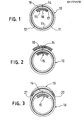
- the reference numeral 10 in FIG. 1 relates to a laminate tube comprising three layers 11, 12 and 13.
- the intermediate layer 12 is a metal foil layer forming a gas and vapor barrier, usually of aluminium, having a thickness in the interval 5 to 40 microns.
- the layers 11, 13 may be obtained as a coating or a film.
- the laminate comprising said layers, which of course may be supplemented by additional layers, is formed into a generally cylindrical shape having the edges thereof placed edge against edge for forming a longitudinal joint 14.
- a strip -15 On the inside of the tube body this joint is covered by a strip -15.
- the strip 15 also comprises three layers 16, 17 and 18.
- the intermediate layer 17 is a metal foil layer, usually of aluminium, having a thickness in the interval 40 to 200 microns, thus a thickness considerably thicker than the thickness of the metal foil layer 11 of the tube body.
- a certain thickness taken from the lower region of the tube interval 5 to 40 microns corresponds to a certain thickness taken from the lower region of the tube interval 5 to 40 microns, in the actual case 5 microns.
- the layers 16 and 18 are polyolefine layers selected by taking into consideration the heat sealing characteristics against the polyolefine layer 13 of the tube body.
- the thicknesses of the layers 16, 18 may for instance fall in the interval 10 to 50 microns.
- the layers may be applied as a coating or as a film.
- the thickness relation between the foil 17 and the foil 12 implies most interesting handling characteristics of the entire structure, i.e. the tube body 10 and the strip 15. It has been found that the strip provides the "dead-fold" aimed at for the tube body which per se has a return tendency to the original shape. Additionally, this is achieved by a total contents of metal in the tube considerably less than the metal contents of known laminate tubes having dead-fold characteristics.
- the strip has a very limited width, of the order around 10 per cent or less of the tube body circumference, which means that the total metal contents of the tube body and the strip will be very advantagous, especially as the thickness of the metal foil 12 of the tube body may be reduced. Basically one has only to consider the function thereof as a gas and vapor barrier. The width of the strip may also be minimized and you have merely to see to it that the width is such that there is formed on both sides of the longitudinal joint a barrier against penetration into the longitudinal joint of substances of the filling goods having delaminating characteristics.
- FIG. 2 there is shown another embodiment of the invention, where a strip 19 is arranged on the outside of the tube along the joint 14.
- This outside strip protects against repeated folding or pressing together of the tube body around a line coinciding with the longitudinal joint 14.
- FIG. 1 it is also possible to reduce the metal thickness of the actual strip.
- FIG. 3 it is also possible to obtain a proper and smooth transition between the strip 19 and the tube body 10.
- Such a method may also be applied to the inside strip 15, if a metal edge contact is not desirable in specific applications, for instance when the tube contents is toothpaste, in spite of the fact that such an edge or edges form a very limited contact surface.
- the unfavourable risk of metal contact at the joint 14, for instance unfavourable in view of delamination risk, has already been eliminated by means of the strip 15.
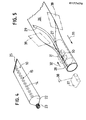
- FIG. 4 there is shown in a perspective view a complete laminate tube according to the invention comprising a tube body 10, a breast 22 and a discharge opening 23.
- the conventional type of cross sealing 25 is arranged perpendicular to a plane housing the joint 14.
- the longitudinal joint 14 will not be “broken up”, instead the inner strip 15 forms a stiffening support for the forces acting when the tube is pressed together when discharging the contents.
- FIG. 5 it is shown how a laminate web, intended for tube bodies 10, is folded by means of a pair of folding rails 39 into a cylindrical shape over a mandrel 27 and placed over this mandrel such that a longitudinal joint 28 having the edges of the laminate placed edge against edge is obtained.
- the laminate 26 is of the basic structure described in connection with the tube body 10 in FIG. 1.
- a further laminate strip 29, in the shape of a narrow ribbon, having the structure described with reference to FIG. 1, is fed against and along the mandrel 27 in register with the joint 28.
- a high frequency welding device for instance an induction welding device 30 is arranged over the mandrel 27 and the joint 28 and directs the magnetic field thereof against the welding region, i.e. the joint 28 and the strip 29 below the joint.
- the necessary heating for softening of the thermoplastics material is obtained by induction in the metal foil of the strip 15.
- a sealing pressure device in the shape of an endless belt 31 is arranged.
- the belt is oriented in register with the joint 28 and the direction of movement appears from the arrow 32.
- the speed of movement of the belt generally corresponds to the speed the web 26 is formed into a tube on the mandrel 27 when the web 26 is forwared in the direction of the arrow 33.
- FIG. 6 there is shown a section through the mandrel 27 and the welding and sealing pressure device.
- the welding device has been shown as one single loop of an electric coil 30 which directs the induction field against the joint 14 and the strip 15 along the centre axis 33 thereof.
- the sealing pressure belt 31 presses the edges of the web 26 together and presses the strip 29 against the web 26 which has been formed into tube-shape during the necessary time period after the welding device 30 has been passed, giving the weld seam the possibility of stabilization without any real mechanical strain.
- this groove 35 may have a somewhat over-dimensioned width in order to allow flowing out of plastics onto the strip 29, such that the metal edges thereof are covered by the plastics.
- This shape of the recess 35 has been indicated by the broken lines 36.
- a corresponding welding and sealing pressure device preferably is arranged after the devices 30, 31 in FIG. 5 (seen in the machine direction).
- FIG. 7 there is shown an all-metal tube breast 39 having a circumferential recess 40 forming a support surface for the tube body.
- the tube body is formed as a stackable body, for instance from a trapezoid blank 42 as shown in FIG. 8, there is a nesting arrangement 41 formed as a circumferential shoulder for preventing adherence between individual tube bodies where such bodies are stacked, for instance in the storage of a filling machine.
- the joint of the tube body may be an overlap joint if required.
Landscapes
- Engineering & Computer Science (AREA)
- Mechanical Engineering (AREA)
- Physics & Mathematics (AREA)
- Thermal Sciences (AREA)
- Tubes (AREA)
- Lining Or Joining Of Plastics Or The Like (AREA)
- Laminated Bodies (AREA)
- External Artificial Organs (AREA)
- Wrappers (AREA)
- Measuring Or Testing Involving Enzymes Or Micro-Organisms (AREA)
- Saccharide Compounds (AREA)
- Investigating Or Analysing Biological Materials (AREA)
- Containers And Plastic Fillers For Packaging (AREA)
- Details Of Indoor Wiring (AREA)
- Electric Cable Installation (AREA)
Abstract
Description
- The present invention relates to a packaging tube, more precisely a tube of the laminate tube type. The invention relates also to a method and a device for manufacturing of the actual tube.
- The term laminate tube means a tube manufactured from a laminate comprising metal foil, usually aluminium foil. Laminate tubes are well known. As time has passed by laminate materials as well as the manufacturing technique have been developed.
- The market has shown a very high degree of acceptance and people within the art have realized that the laminate technique offers an alternative to metal tubes and that such alternative is an interesting one for several reasons, not at least from a cost point of view when packaging products requiring sofisticated barrier properties of the packaging tube.
- A frequently occuring problem, has to do with the provision of handling characteristics which would be acceptable.
- The consumer wants to roll up the tube as it is being emptied, and he/she prefers a "dead" material in such cases, i.e. a material without a tendency of returning or without "a mechanical memory". The term used within the actual technical field is a material having pronounced dead-fold characteristics. The term dead-fold falls under a broader term called "resilience" and frequently used when defining the overall characteristics of a metal foil containing laminate.
- Briefly the problem may be identified by recognizing the fact that a laminate tube is more like an all-plastics tube than a metal tube (for instance lead or zinc tube), unless specific measures are taken.
- The return tendency the laminate tube has, without such measures, for instance means that the contents of the tube will be exposed to a large volume of air when the tube returns to its original shape although the contents of the tube has decreased drastically.
- So far the unfavourable return tendency of the metal foil laminate has been dealt with by applying either one of three basic methods.
- According to a first method, described in US 3 976 224, there is required a large amount of metal in the tube body. Double metal foils, one at each side of a centre polymer layer, are used for a laminate having additional layers of plastic and binder.
- Having in mind that the contents of metal, generally aluminium, is the impact factor from a cost point of view, this increased cost means a large drawback for a mass product of the present type, without any real inherent value.
- According to a second method, an older one described in US 3 505 143 or a younger in EP 0 115 111, paper in combination with a multilayer laminate, comprising i.a. metal and polymer, forms the basis for form stability and dead-fold. This tube structure means a high cost of material and a complex and expensive manufacturing method.
- The third method, which is described in EP 0 084 922, makes use of a polymer layer having an organic additive as a filler. The layer having such filler forms the element providing dead-fold by forming grooves or other weakening lines in the layer for counter-acting a return tendency. From a barrier point of view this method involves a dangerous working of the material of the outer layer protecting the metal foil. There is a risk for damage of the metal foil. Additionally, the possibility of the important step of printing the tube will be negatively affected.
- Thus, there is a need to provide an alternative to the known technique of giving laminate tubes dead-fold characteristics.
- The alternative which is aimed at should be in-line with well established tube handling methods, but eliminate cost increasing addition of material.
- Having this in mind the invention therefore provides, in the broadest sense thereof, a packaging tube, comprising a body of a metal foil containing laminate, a tube breast having an discharge opening at one end of the body, and an elongated element attached to the tube body and extending generally along the entire length thereof.
- The tube is characterized in that the elongated element comprises a strip having dead-fold characteristics manufactured from a metal foil containing material, and that the thickness of the metal foil of the tube body falls within the interval 5 to 40 microns, and is selected such that the metal foil of the body is considerably thinner than the thickness of the metal foil of the strip which falls within the
interval 40 to 200 microns - The thickness relation preferably is such that a foil thickness of the tube body of for instance 5 microns corresponds to a strip thickness of 200 microns, i.e. a certain thickness taken from the lower region of the tube body interval corresponds to a certain thickness taken from the upper region of the strip interval.
- In the basic embodiment the strip is arranged on the inside of the tube body and has such a width that on both sides of a longitudinal tube body joint there is formed a barrier against penetration into the longitudinal joint of substances of the filling goods having delaminating characteristics.
- As the heat sealing method is the most preferable method for longitudinal sealing of tubes, the side of the strip facing the inside of the tube body is provided with a layer of a polyolefine plastics of a type being heat sealing compatible with the inside of the tube body.
- In order to avoid exposure of the metal foil edges to the contents of the tube, if necessary, the strip has a plastics layer of an over-dimensioned thickness before attaching the strip, such that the excess amount of plastics will "flow out" and cover the edges of the strip after it has been sealed by heat sealing.
- In order to protect the longitudinal joint there may also be arranged an external strip over the longitudinal joint.
- In order to adapt the strip to the tube body the plastics layer of the strip preferably is over-dimensioned and arranged such that it covers the edges of the strip after it has been heat sealed.
- In a preferred embodiment the laminate of the tube body is arranged edge against edge.
- In one embodiment the metal foil containing tube body and the dead-fold strip are attached to an all-metal breast, for instance of aluminium.
- For making the tube stackable the tube body may be made conical.
- In one embodiment the tube body is made from a trapezoid blank.
- The invention also provides a method for manufacturing of a packaging tube, comprising a body of a metal foil containing laminate and a tube breast having a discharge opening at one end of the body, and an elongated element attached to the tube body such that it extends in the longitudinal direction of the body and generally along the entire length thereof.
- The method is characterized in that the elongated element is selected such that it comprises a strip of a metal foil containing material having dead-fold characteristics with a metal foil thickness in the
interval 40 to 200 microns and selected such that the metal foil of the strip is considerably thicker than the metal foil of the tube body which faces within the interval 5 to 40 microns. - A web of a metal foil containing laminate is formed into tube-shape on a mandrel, a strip of metal foil containing laminate is placed over the longitudinal joint that is obtained and is heat sealed against the tube-shaped body.
- The relation between the two metal foil intervals preferably is such that a certain thickness taken from the lower region of the tube body interval corresponds to a certain thickness taken from the upper region of the strip interval, i.e. a five microns foil for the tube body for instance corresponds to the upper extreme value of the 40 to 200 microns interval, i.e. 200 microns.
- In the basic embodiment the strip is placed inside the tube body by guiding it in a groove in a mandrel arranged to place the strip in register with the longitudinal joint of the tube body that is obtained.
- The heat sealing preferably is accomplished by high frequency welding, for instance induction welding, by arranging a magnetic field producing member for directing the field against the region of the longitudinal joint, and by arranging a member for providing a sealing pressure along the joint.
- Another method of heat sealing comprises ultra-sound welding.
- The necessary cooling of the welding region is obtained by providing the mandrel with channels for a cooling medium for cooling the welding region.
- The plastics for protecting the edges of the metal foil preferably is obtained by arranging the mandrel with outflow zones for receiving the plastics to cover the metal foil edges.
- In order to avoid an undesired mechanical strain in the welding region the member for providing the sealing pressure preferably is formed as an endless belt which is given generally the same speed as the speed at which the tube-shaped body is transported over the mandrel.
- The invention also provides a device for manufacturing a packaging tube comprising a body of a metal foil containing laminate and a tube breast having a discharge opening at one end of the body.
- The device is characterized by a mandrel device having a longitudinal recess therein for guiding a metal foil containing laminate strip, by means for forming a web of a metal foil containing laminate into tube-shape, and by means for heat sealing the strip to the inside of the web in register with the longitudinal joint obtained in the web.
- In the preferred embodiment said means for heat sealing preferably comprises a high frequency welding device, for instance an induction welding device, and an endless belt for providing a sealing pressure.
- For obtaining an optimum temperature distribution there are preferably also formed channels for a cooling medium in the mandrel.
-
- FIG. 1 in a cross section shows a tube body according to a first embodiment of the invention,
- FIG. 2 shows a tube body according to another embodiment,
- FIG. 3 shows the embodiment in FIG. 2 in a somewhat modified version,
- FIG. 4 in a perspective view shows the tube having a strip at the inside thereof,
- FIG. 5 is a basic diagram showing a preferred method of manufacturing the tube according to the invention,
- FIG. 6 is a schematic section through the tube mandrel and the positioning and sealing pressure device in FIG. 5,
- FIG. 7 in a cross section shows a tube breast of metal, for instance aluminium, and
- FIG. 8 in a plan view shows a blank for a conical tube.
- The
reference numeral 10 in FIG. 1 relates to a laminate tube comprising threelayers intermediate layer 12 is a metal foil layer forming a gas and vapor barrier, usually of aluminium, having a thickness in the interval 5 to 40 microns. On this layer there are attached, if necessary by use of primer or other auxiliary means, polyolefine layers 11, 13, usually layers of
polyethylene or polypropylene, having a thickness of typically 10 to 50 microns. Thelayers - The laminate comprising said layers, which of course may be supplemented by additional layers, is formed into a generally cylindrical shape having the edges thereof placed edge against edge for forming a longitudinal joint 14. On the inside of the tube body this joint is covered by a strip -15. The
strip 15 also comprises threelayers intermediate layer 17 is a metal foil layer, usually of aluminium, having a thickness in theinterval 40 to 200 microns, thus a thickness considerably thicker than the thickness of themetal foil layer 11 of the tube body. - A certain thickness taken from the upper region of a
strip interval 40 to 200 microns, for instance 200 microns, corresponds to a certain thickness taken from the lower region of the tube interval 5 to 40 microns, in the actual case 5 microns. Thus, in reality there is a substantial difference between the thickness of the metal foils in the tube body and the strip, respectively. - The
layers polyolefine layer 13 of the tube body. - The thicknesses of the
layers interval 10 to 50 microns. The layers may be applied as a coating or as a film. - The thickness relation between the
foil 17 and thefoil 12 implies most interesting handling characteristics of the entire structure, i.e. thetube body 10 and thestrip 15. It has been found that the strip provides the "dead-fold" aimed at for the tube body which per se has a return tendency to the original shape. Additionally, this is achieved by a total contents of metal in the tube considerably less than the metal contents of known laminate tubes having dead-fold characteristics. - Although the thickness of the
layer 17 of the strip may be a considerable thickness in relation to the thickness of thelayer 13, the strip has a very limited width, of the order around 10 per cent or less of the tube body circumference, which means that the total metal contents of the tube body and the strip will be very advantagous, especially as the thickness of themetal foil 12 of the tube body may be reduced. Basically one has only to consider the function thereof as a gas and vapor barrier. The width of the strip may also be minimized and you have merely to see to it that the width is such that there is formed on both sides of the longitudinal joint a barrier against penetration into the longitudinal joint of substances of the filling goods having delaminating characteristics. - In FIG. 2 there is shown another embodiment of the invention, where a
strip 19 is arranged on the outside of the tube along the joint 14. This outside strip protects against repeated folding or pressing together of the tube body around a line coinciding with the longitudinal joint 14. By using the double strip structure in FIG. 1 it is also possible to reduce the metal thickness of the actual strip. As shown in FIG. 3, it is also possible to obtain a proper and smooth transition between thestrip 19 and thetube body 10. - In order to accomplish this, one has to see to it that the external layer on the
strip 19 is somewhat over-dimensioned such that there are formedtransition regions - Such a method may also be applied to the
inside strip 15, if a metal edge contact is not desirable in specific applications, for instance when the tube contents is toothpaste, in spite of the fact that such an edge or edges form a very limited contact surface. The unfavourable risk of metal contact at the joint 14, for instance unfavourable in view of delamination risk, has already been eliminated by means of thestrip 15. - In FIG. 4 there is shown in a perspective view a complete laminate tube according to the invention comprising a
tube body 10, abreast 22 and adischarge opening 23. The conventional type of cross sealing 25 is arranged perpendicular to a plane housing the joint 14. When the tube is handled in the normal way the longitudinal joint 14 will not be "broken up", instead theinner strip 15 forms a stiffening support for the forces acting when the tube is pressed together when discharging the contents. - In FIG. 5 it is shown how a laminate web, intended for
tube bodies 10, is folded by means of a pair of folding rails 39 into a cylindrical shape over amandrel 27 and placed over this mandrel such that a longitudinal joint 28 having the edges of the laminate placed edge against edge is obtained. The laminate 26 is of the basic structure described in connection with thetube body 10 in FIG. 1. - A
further laminate strip 29, in the shape of a narrow ribbon, having the structure described with reference to FIG. 1, is fed against and along themandrel 27 in register with the joint 28. - A high frequency welding device, for instance an
induction welding device 30 is arranged over themandrel 27 and the joint 28 and directs the magnetic field thereof against the welding region, i.e. the joint 28 and thestrip 29 below the joint. The necessary heating for softening of the thermoplastics material is obtained by induction in the metal foil of thestrip 15. - In order to obtain the necessary pressure in the welding region a sealing pressure device in the shape of an
endless belt 31 is arranged. The belt is oriented in register with the joint 28 and the direction of movement appears from thearrow 32. The speed of movement of the belt generally corresponds to the speed theweb 26 is formed into a tube on themandrel 27 when theweb 26 is forwared in the direction of thearrow 33. - In FIG. 6 there is shown a section through the
mandrel 27 and the welding and sealing pressure device. The welding device has been shown as one single loop of anelectric coil 30 which directs the induction field against the joint 14 and thestrip 15 along thecentre axis 33 thereof. - The sealing
pressure belt 31 presses the edges of theweb 26 together and presses thestrip 29 against theweb 26 which has been formed into tube-shape during the necessary time period after thewelding device 30 has been passed, giving the weld seam the possibility of stabilization without any real mechanical strain. - In order to speed up the cooling and stabilization of the
weld seam channels 34 for a cooling fluid are arranged in themandrel 27. - For guiding the
strip 29 there are arranged alongitudinal groove 35 in the mandrel. After the welding device 30 (seen in the machine direction) this groove may have a somewhat over-dimensioned width in order to allow flowing out of plastics onto thestrip 29, such that the metal edges thereof are covered by the plastics. This shape of therecess 35 has been indicated by thebroken lines 36. - In that case where an
outside strip 19 is needed, a corresponding welding and sealing pressure device preferably is arranged after thedevices - Such further arrangements have been denoted by the
reference numeral 37 and an outerstrip forming web 38 has also been indicated. - In FIG. 7 there is shown an all-
metal tube breast 39 having acircumferential recess 40 forming a support surface for the tube body. - In that case where the tube body is formed as a stackable body, for instance from a trapezoid blank 42 as shown in FIG. 8, there is a
nesting arrangement 41 formed as a circumferential shoulder for preventing adherence between individual tube bodies where such bodies are stacked, for instance in the storage of a filling machine. - Although specific embodiments of the invention have been described with reference to the specific examples given, it is realized that modifications and alternatives are possible within the scope of the accompanying claims.
- For instance, the joint of the tube body, may be an overlap joint if required.
Claims (22)
Priority Applications (1)
| Application Number | Priority Date | Filing Date | Title |
|---|---|---|---|
| AT85850292T ATE44701T1 (en) | 1984-10-02 | 1985-09-20 | TUBE, PROCESS AND APPARATUS FOR THEIR MANUFACTURE. |
Applications Claiming Priority (2)
| Application Number | Priority Date | Filing Date | Title |
|---|---|---|---|
| SE8404921 | 1984-10-02 | ||
| SE8404921A SE445031B (en) | 1984-10-02 | 1984-10-02 | PACKAGING TUBES AND PROCEDURES AND DEVICES FOR MANUFACTURING THEREOF |
Publications (3)
| Publication Number | Publication Date |
|---|---|
| EP0177470A2 true EP0177470A2 (en) | 1986-04-09 |
| EP0177470A3 EP0177470A3 (en) | 1987-08-19 |
| EP0177470B1 EP0177470B1 (en) | 1989-07-19 |
Family
ID=20357203
Family Applications (1)
| Application Number | Title | Priority Date | Filing Date |
|---|---|---|---|
| EP85850292A Expired EP0177470B1 (en) | 1984-10-02 | 1985-09-20 | A tube and a method and a device for manufacturing of the tube |
Country Status (9)
| Country | Link |
|---|---|
| US (1) | US4733800A (en) |
| EP (1) | EP0177470B1 (en) |
| JP (1) | JPS6186258A (en) |
| AT (1) | ATE44701T1 (en) |
| DE (1) | DE3571589D1 (en) |
| DK (1) | DK445485A (en) |
| FI (1) | FI78042C (en) |
| NO (1) | NO853842L (en) |
| SE (1) | SE445031B (en) |
Cited By (16)
| Publication number | Priority date | Publication date | Assignee | Title |
|---|---|---|---|---|
| WO1988002690A3 (en) * | 1986-10-15 | 1988-07-28 | Maegerle Karl Lizenz | Process and device for producing tubular bodies, in particular for packing tubes |
| EP0252040A3 (en) * | 1986-06-02 | 1989-03-01 | Ab Akerlund & Rausing | Method and device for the scrap-free manufacture of coated profiles and thermally shaped containers |
| EP0283229A3 (en) * | 1987-03-14 | 1990-10-24 | Hokkai Can Co., Ltd. | Apparatus for manufacturing a tubular member |
| WO1994004343A1 (en) * | 1992-08-26 | 1994-03-03 | Kmk Karl Mägerle Lizenz Ag | Process for manufacturing tubular bodies for packaging tubes |
| US6761724B1 (en) * | 1997-09-19 | 2004-07-13 | Eberhard-Karls-Universität Tübingen Universitätsklinikum | Method and device for entering the subretinal region of the eye |
| WO2007113782A3 (en) * | 2006-04-06 | 2007-12-06 | Aisapack Holding Sa | Packaging tubular body made of thermoplastic material with embedded strip |
| WO2007113781A3 (en) * | 2006-04-06 | 2007-12-06 | Aisapack Holding Sa | Flexible multilayer structure for tubes |
| WO2007113780A3 (en) * | 2006-04-06 | 2008-01-10 | Aisapack Holding Sa | Package formed by a butt-sealed film |
| EP1905570A1 (en) * | 2006-09-28 | 2008-04-02 | Aisapack Holding SA | Process and apparatus for internal welding of plastic tubes |
| RU2323828C2 (en) * | 2002-08-19 | 2008-05-10 | Аиса Отомасьон Эндюстриэль Са | Device for tube packing and producing |
| EP2674368A1 (en) * | 2012-06-15 | 2013-12-18 | Aisapack Holding SA | Butt-welded tubular packaging body |
| EP2960045A1 (en) * | 2014-06-23 | 2015-12-30 | Tesseraux Spezialverpackungen GmbH | Bag with round base, method for producing a bag with a round base and hot melt adhesive package |
| EP2276622B1 (en) | 2008-04-10 | 2016-12-21 | Aisapack Holding SA | Method for manufacturing tubes by welding |
| EP3845469A4 (en) * | 2018-08-30 | 2022-06-15 | Yoshino Kogyosho Co., Ltd. | Tube container |
| EP4053030A1 (en) * | 2021-03-02 | 2022-09-07 | Aisapack Holding SA | Tubular body for forming a packaging and packaging therewith |
| RU2851583C1 (en) * | 2021-03-02 | 2025-11-25 | Айзапак Холдинг Са | Tubular housing for creating packaging and packaging containing such a housing |
Families Citing this family (30)
| Publication number | Priority date | Publication date | Assignee | Title |
|---|---|---|---|---|
| JPH04131581A (en) * | 1990-09-25 | 1992-05-06 | Bridgestone Corp | Low permeable rubber hose |
| US5665441A (en) * | 1991-10-29 | 1997-09-09 | Daiwa Seiko, Inc. | Hollow cylindricall member |
| US5393178A (en) * | 1993-03-08 | 1995-02-28 | Daraz; Bruno | Engraving quill holders |
| US5344049A (en) * | 1993-06-28 | 1994-09-06 | Macdonald Florence C | Vinyl or plastic dispensing tube for pastes, creams, or gels |
| US5611373A (en) * | 1995-04-27 | 1997-03-18 | Handy & Harman Automotive Group, Inc. | Laminated fuel line and connector |
| DE19535669A1 (en) * | 1995-09-26 | 1997-04-03 | 4P Rube Goettingen Gmbh | container |
| US6332560B1 (en) * | 2000-12-07 | 2001-12-25 | Max Rosenberg | Collapsible dispensing tube |
| FR2846275B1 (en) * | 2002-10-25 | 2004-12-10 | Cebal Sas | IMPROVEMENT OF A PROCESS FOR THE MANUFACTURE OF FLEXIBLE PLASTIC OR METALLOPLASTIC TUBES |
| US7360461B2 (en) * | 2004-09-23 | 2008-04-22 | Aircuity, Inc. | Air monitoring system having tubing with an electrically conductive inner surface for transporting air samples |
| US7216556B2 (en) * | 2004-09-23 | 2007-05-15 | Aircuity, Inc. | Tubing for transporting air samples in an air monitoring system |
| JP2006175682A (en) * | 2004-12-21 | 2006-07-06 | Tokai Rubber Ind Ltd | Low permeable composite hose |
| DE102005003922A1 (en) * | 2005-01-27 | 2006-08-03 | Ccl Label Gmbh | Sealable tubular polymer foil laminate has at least a sealable outer print foil of a high density polyethylene material and an inner polymer support foil with similar melting point to seal with print foil |
| DE202005004135U1 (en) * | 2005-03-11 | 2005-05-19 | Klocke Verpackungs-Service Gmbh | Multi-component packaging with applicator |
| WO2007113783A1 (en) * | 2006-04-06 | 2007-10-11 | Aisapack Holding S.A. | Package formed by a butt-sealed multilayer film |
| EP1884349A1 (en) * | 2006-07-31 | 2008-02-06 | Aisapack Holding SA | Container built from butt joined multilayer film |
| US7422036B2 (en) * | 2006-07-28 | 2008-09-09 | Electrolux Home Products, Inc. | Dishwasher manifold assembly and associated method |
| MX2009010730A (en) * | 2007-04-05 | 2009-10-26 | Procter & Gamble | One piece dispensing component. |
| US20100084427A1 (en) * | 2008-10-03 | 2010-04-08 | Kardach Gerald E | Folding Tube |
| DE102011055728A1 (en) * | 2011-06-06 | 2012-12-06 | Linhardt Gmbh & Co. Kg | Method for producing packaging |
| US9574686B2 (en) * | 2011-06-06 | 2017-02-21 | Essel Propack Ltd. | Invisible seam laminated article and process of manufacture |
| EP3200999B1 (en) * | 2014-10-24 | 2019-12-18 | Colgate-Palmolive Company | Method of making a tube and tube |
| JP2016124296A (en) * | 2014-12-31 | 2016-07-11 | エルネスト・レオネッリErnesto Leonelli | Continuous rotary heat-sealing machine, particularly for joining heat-sealable films, papers or ribbons |
| US9919847B2 (en) * | 2016-06-01 | 2018-03-20 | Klecher, L.L.C. | Integrated squeezable dispensing container |
| US10377533B2 (en) * | 2016-06-01 | 2019-08-13 | Klecher, Llc | Integrated squeezable dispensing container |
| JP6932429B2 (en) * | 2017-03-24 | 2021-09-08 | 株式会社吉野工業所 | Laminated tube container |
| EP3606739B1 (en) * | 2017-04-05 | 2024-01-03 | Kimpai Lamitube Co., Ltd. | Tubular container with invisible longitudinal overlapped side seam |
| JP2020163731A (en) * | 2019-03-29 | 2020-10-08 | 凸版印刷株式会社 | Packaging tubes, packaging tube manufacturing methods, and manufacturing equipment |
| JP2022128043A (en) * | 2021-02-22 | 2022-09-01 | 凸版印刷株式会社 | Tube container and manufacturing method of tube container |
| JP7600594B2 (en) * | 2020-09-30 | 2024-12-17 | 大日本印刷株式会社 | Tube container |
| EP4082757A1 (en) | 2021-04-26 | 2022-11-02 | Aisapack Holding SA | Packaging in which the bonding is concealed in the printing and manufacturing method |
Family Cites Families (17)
| Publication number | Priority date | Publication date | Assignee | Title |
|---|---|---|---|---|
| US1188115A (en) * | 1915-04-01 | 1916-06-20 | Uldric Thompson Jr | Collapsible tube. |
| FR705054A (en) * | 1931-08-29 | 1931-06-01 | Goods receiving tube | |
| FR845060A (en) * | 1938-04-19 | 1939-08-10 | Tube for plastic fluids | |
| US2287259A (en) * | 1940-07-01 | 1942-06-23 | Lindstrom Carl | Collapsible tube or receptacle |
| US2430046A (en) * | 1942-11-18 | 1947-11-04 | Dreyfus Camille | Collapsible tube |
| US2401784A (en) * | 1943-01-02 | 1946-06-11 | Zahara Walter | Collapsible tube |
| US2605018A (en) * | 1949-10-05 | 1952-07-29 | Santy M Croce | Dispensing tube |
| US3207651A (en) * | 1961-07-13 | 1965-09-21 | Procter & Gamble | Apparatus for making tubing from a continuous web |
| CH385723A (en) * | 1962-09-03 | 1964-12-15 | Nestle Sa | Compressible container of plastic, more particularly tube for non-solid materials |
| US3211342A (en) * | 1963-10-09 | 1965-10-12 | Colgate Palmolive Co | Collapsible plastic tubes |
| US3347419A (en) * | 1965-01-21 | 1967-10-17 | American Can Co | Collapsible dispensing tube |
| DE1729018A1 (en) * | 1967-12-27 | 1971-06-03 | Spiess C F & Sohn | Process for producing tubes, in particular tube bodies from foils |
| GB1421176A (en) * | 1971-12-25 | 1976-01-14 | Yoshino Kogyosho Co Ltd | Collapsible tube |
| US3976224A (en) * | 1972-01-10 | 1976-08-24 | The Procter & Gamble Company | Collapsible dispensing tubes |
| US4196825A (en) * | 1975-09-08 | 1980-04-08 | Colgate-Palmolive Company | Laminated collapsible tube |
| AT373200B (en) * | 1978-11-27 | 1983-12-27 | Mepag Ag | METHOD FOR TAPPING A CYLINDRICAL PLASTIC ALUMINUM LAMINATE TUBE |
| US4539259A (en) * | 1984-07-02 | 1985-09-03 | Crown Zellerbach Corporation | Laminate for making tubes |
-
1984
- 1984-10-02 SE SE8404921A patent/SE445031B/en not_active IP Right Cessation
-
1985
- 1985-09-13 FI FI853514A patent/FI78042C/en not_active IP Right Cessation
- 1985-09-19 US US06/777,634 patent/US4733800A/en not_active Expired - Fee Related
- 1985-09-20 EP EP85850292A patent/EP0177470B1/en not_active Expired
- 1985-09-20 AT AT85850292T patent/ATE44701T1/en not_active IP Right Cessation
- 1985-09-20 DE DE8585850292T patent/DE3571589D1/en not_active Expired
- 1985-09-30 NO NO853842A patent/NO853842L/en unknown
- 1985-10-01 JP JP60219020A patent/JPS6186258A/en active Granted
- 1985-10-01 DK DK445485A patent/DK445485A/en not_active Application Discontinuation
Cited By (36)
| Publication number | Priority date | Publication date | Assignee | Title |
|---|---|---|---|---|
| EP0252040A3 (en) * | 1986-06-02 | 1989-03-01 | Ab Akerlund & Rausing | Method and device for the scrap-free manufacture of coated profiles and thermally shaped containers |
| EP0264663A3 (en) * | 1986-10-15 | 1988-09-14 | Kmk Karl Magerle Lizenz Ag | Method and apparatus for producing tubular articles, especially packaging tubes |
| AU589298B2 (en) * | 1986-10-15 | 1989-10-05 | Kmk Lizence Ltd | Process and device for producing tubular bodies, in particular for packing tubes |
| WO1988002690A3 (en) * | 1986-10-15 | 1988-07-28 | Maegerle Karl Lizenz | Process and device for producing tubular bodies, in particular for packing tubes |
| EP0283229A3 (en) * | 1987-03-14 | 1990-10-24 | Hokkai Can Co., Ltd. | Apparatus for manufacturing a tubular member |
| WO1994004343A1 (en) * | 1992-08-26 | 1994-03-03 | Kmk Karl Mägerle Lizenz Ag | Process for manufacturing tubular bodies for packaging tubes |
| US6761724B1 (en) * | 1997-09-19 | 2004-07-13 | Eberhard-Karls-Universität Tübingen Universitätsklinikum | Method and device for entering the subretinal region of the eye |
| RU2323828C2 (en) * | 2002-08-19 | 2008-05-10 | Аиса Отомасьон Эндюстриэль Са | Device for tube packing and producing |
| WO2007113781A3 (en) * | 2006-04-06 | 2007-12-06 | Aisapack Holding Sa | Flexible multilayer structure for tubes |
| WO2007113780A3 (en) * | 2006-04-06 | 2008-01-10 | Aisapack Holding Sa | Package formed by a butt-sealed film |
| US8916247B2 (en) | 2006-04-06 | 2014-12-23 | Aisapack Holding S.A. | Thermoplastic tubular packaging body with an embedded strip |
| RU2449932C2 (en) * | 2006-04-06 | 2012-05-10 | Айзапак Холдинг С.А. | Flexible multilayer structure for tubes |
| US8852705B2 (en) | 2006-04-06 | 2014-10-07 | Aisapack Holding S.A. | Packaging formed from a butt-welded film |
| CN101410243B (en) * | 2006-04-06 | 2011-10-12 | 艾萨帕克控股公司 | Packaging formed from butt-welded film |
| RU2437765C2 (en) * | 2006-04-06 | 2011-12-27 | Айзапак Холдинг С.А. | Package formed by butt joined film |
| US8580363B2 (en) | 2006-04-06 | 2013-11-12 | Aisapack Holding S.A. | Flexible multilayer structure for tubes |
| WO2007113782A3 (en) * | 2006-04-06 | 2007-12-06 | Aisapack Holding Sa | Packaging tubular body made of thermoplastic material with embedded strip |
| US20120164359A1 (en) * | 2006-09-28 | 2012-06-28 | Aisapack Holding S.A. | Process and device for the internal welding of plastic tubes |
| US8329270B2 (en) * | 2006-09-28 | 2012-12-11 | Aisapack Holding S.A. | Process and device for the internal welding of plastic tubes |
| RU2438871C2 (en) * | 2006-09-28 | 2012-01-10 | Айзапак Холдинг С.А. | Method and device for welding plastic tubes from inside |
| WO2008038206A3 (en) * | 2006-09-28 | 2008-06-19 | Aisapack Holding Sa | Method and device for soldering the inside of plastic tubes |
| EP1905570A1 (en) * | 2006-09-28 | 2008-04-02 | Aisapack Holding SA | Process and apparatus for internal welding of plastic tubes |
| US8157941B2 (en) | 2006-09-28 | 2012-04-17 | Aisapack Holding S.A. | Process for the internal welding of plastic tubes |
| EP2276622B1 (en) | 2008-04-10 | 2016-12-21 | Aisapack Holding SA | Method for manufacturing tubes by welding |
| US11124342B2 (en) | 2012-06-15 | 2021-09-21 | Aisapack Holding S.A. | Butt-welded tubular packaging body |
| EP2674368A1 (en) * | 2012-06-15 | 2013-12-18 | Aisapack Holding SA | Butt-welded tubular packaging body |
| WO2013186723A2 (en) | 2012-06-15 | 2013-12-19 | Aisapack Holding S.A. | Butt-welded tubular packaging body |
| WO2013186723A3 (en) * | 2012-06-15 | 2014-02-27 | Aisapack Holding S.A. | Butt-welded tubular packaging body |
| RU2642043C2 (en) * | 2012-06-15 | 2018-01-23 | Айзапак Холдинг С.А. | Tubular pack produced by butt welding |
| EP2960045A1 (en) * | 2014-06-23 | 2015-12-30 | Tesseraux Spezialverpackungen GmbH | Bag with round base, method for producing a bag with a round base and hot melt adhesive package |
| EP3845469A4 (en) * | 2018-08-30 | 2022-06-15 | Yoshino Kogyosho Co., Ltd. | Tube container |
| US11542066B2 (en) | 2018-08-30 | 2023-01-03 | Yoshino Kogyosho Co., Ltd. | Tube container |
| EP4053030A1 (en) * | 2021-03-02 | 2022-09-07 | Aisapack Holding SA | Tubular body for forming a packaging and packaging therewith |
| WO2022185176A1 (en) | 2021-03-02 | 2022-09-09 | Aisapack Holding Sa | Tubular body for forming a packaging and packaging therewith |
| US12448179B2 (en) | 2021-03-02 | 2025-10-21 | Aisapack Holding Sa | Tubular body for forming a packaging and packaging therewith |
| RU2851583C1 (en) * | 2021-03-02 | 2025-11-25 | Айзапак Холдинг Са | Tubular housing for creating packaging and packaging containing such a housing |
Also Published As
| Publication number | Publication date |
|---|---|
| SE8404921L (en) | 1986-04-03 |
| FI853514L (en) | 1986-04-03 |
| EP0177470B1 (en) | 1989-07-19 |
| JPH0515174B2 (en) | 1993-02-26 |
| SE8404921D0 (en) | 1984-10-02 |
| SE445031B (en) | 1986-05-26 |
| ATE44701T1 (en) | 1989-08-15 |
| FI853514A0 (en) | 1985-09-13 |
| DK445485A (en) | 1986-04-03 |
| JPS6186258A (en) | 1986-05-01 |
| NO853842L (en) | 1986-04-03 |
| DK445485D0 (en) | 1985-10-01 |
| FI78042C (en) | 1989-06-12 |
| FI78042B (en) | 1989-02-28 |
| DE3571589D1 (en) | 1989-08-24 |
| EP0177470A3 (en) | 1987-08-19 |
| US4733800A (en) | 1988-03-29 |
Similar Documents
| Publication | Publication Date | Title |
|---|---|---|
| US4733800A (en) | Tube and a method and a device for manufacturing of the tube | |
| US4994310A (en) | Flexible packing laminate in the form of sheets or of a web, a method for the manufacture of the laminate and packing containers manufactured from the laminate | |
| RU2107624C1 (en) | Sheet type packing material and method of its manufacture | |
| EP3604159B1 (en) | Laminate tube container | |
| US20170297272A1 (en) | Easy Opening Ream Wrap | |
| GB2116523A (en) | Liquid packaging containers | |
| HRP20020654A2 (en) | Gussetted plastic bag | |
| EP0381922B1 (en) | A laminated material with good gas barrier properties, and a method for the manufacture of the material | |
| JP2001000022U (en) | Flexible packaging material and liquid tight container | |
| JP2021507853A (en) | Bundle with wrap sleeve and outer wrap | |
| FI68028B (en) | FOERPACKNINGSFOLIE | |
| RU2216450C2 (en) | Method of production of semifinished products for bags with sealed edges | |
| GB1559472A (en) | Containers | |
| MXPA99011336A (en) | Valve bag and method for making a valve bag. | |
| SE458197B (en) | FOERPACKNINGSBEHAALLARE | |
| RU2062249C1 (en) | Packing container opener | |
| JP7492132B2 (en) | Film roll, filling method | |
| JP2006513940A (en) | Packaging container and packaging material blank | |
| JPS6333258A (en) | Flexible vessel for liquid | |
| JPS63202434A (en) | Method for manufacturing a body for extruded tubes and its original fabric | |
| KR102170670B1 (en) | laminate sheet for tube vessel and manufacturing method of tube vessel | |
| JP3541450B2 (en) | Tube container manufacturing method | |
| JPS63218340A (en) | Manufacture of can drum for composite can | |
| JPH0671775B2 (en) | Can body for compound cans | |
| JPH09104471A (en) | Cylindrical packaging bag |
Legal Events
| Date | Code | Title | Description |
|---|---|---|---|
| PUAI | Public reference made under article 153(3) epc to a published international application that has entered the european phase |
Free format text: ORIGINAL CODE: 0009012 |
|
| AK | Designated contracting states |
Kind code of ref document: A2 Designated state(s): AT BE CH DE FR GB IT LI LU NL SE |
|
| PUAL | Search report despatched |
Free format text: ORIGINAL CODE: 0009013 |
|
| AK | Designated contracting states |
Kind code of ref document: A3 Designated state(s): AT BE CH DE FR GB IT LI LU NL SE |
|
| 17P | Request for examination filed |
Effective date: 19870914 |
|
| 17Q | First examination report despatched |
Effective date: 19880125 |
|
| GRAA | (expected) grant |
Free format text: ORIGINAL CODE: 0009210 |
|
| AK | Designated contracting states |
Kind code of ref document: B1 Designated state(s): AT BE CH DE FR GB IT LI LU NL SE |
|
| REF | Corresponds to: |
Ref document number: 44701 Country of ref document: AT Date of ref document: 19890815 Kind code of ref document: T |
|
| REF | Corresponds to: |
Ref document number: 3571589 Country of ref document: DE Date of ref document: 19890824 |
|
| ITF | It: translation for a ep patent filed | ||
| ET | Fr: translation filed | ||
| ITTA | It: last paid annual fee | ||
| PG25 | Lapsed in a contracting state [announced via postgrant information from national office to epo] |
Ref country code: LU Free format text: LAPSE BECAUSE OF NON-PAYMENT OF DUE FEES Effective date: 19890930 |
|
| PLBE | No opposition filed within time limit |
Free format text: ORIGINAL CODE: 0009261 |
|
| STAA | Information on the status of an ep patent application or granted ep patent |
Free format text: STATUS: NO OPPOSITION FILED WITHIN TIME LIMIT |
|
| PGFP | Annual fee paid to national office [announced via postgrant information from national office to epo] |
Ref country code: LU Payment date: 19900612 Year of fee payment: 6 |
|
| PGFP | Annual fee paid to national office [announced via postgrant information from national office to epo] |
Ref country code: BE Payment date: 19900615 Year of fee payment: 6 |
|
| 26N | No opposition filed | ||
| PGFP | Annual fee paid to national office [announced via postgrant information from national office to epo] |
Ref country code: CH Payment date: 19900810 Year of fee payment: 6 |
|
| PGFP | Annual fee paid to national office [announced via postgrant information from national office to epo] |
Ref country code: AT Payment date: 19900828 Year of fee payment: 6 |
|
| PGFP | Annual fee paid to national office [announced via postgrant information from national office to epo] |
Ref country code: NL Payment date: 19900930 Year of fee payment: 6 |
|
| PGFP | Annual fee paid to national office [announced via postgrant information from national office to epo] |
Ref country code: GB Payment date: 19910919 Year of fee payment: 7 |
|
| PG25 | Lapsed in a contracting state [announced via postgrant information from national office to epo] |
Ref country code: AT Effective date: 19910920 |
|
| PGFP | Annual fee paid to national office [announced via postgrant information from national office to epo] |
Ref country code: SE Payment date: 19910925 Year of fee payment: 7 |
|
| PG25 | Lapsed in a contracting state [announced via postgrant information from national office to epo] |
Ref country code: LI Effective date: 19910930 Ref country code: CH Effective date: 19910930 Ref country code: BE Effective date: 19910930 |
|
| PGFP | Annual fee paid to national office [announced via postgrant information from national office to epo] |
Ref country code: DE Payment date: 19911025 Year of fee payment: 7 |
|
| PGFP | Annual fee paid to national office [announced via postgrant information from national office to epo] |
Ref country code: FR Payment date: 19920330 Year of fee payment: 7 |
|
| BERE | Be: lapsed |
Owner name: AKERLUND & RAUSING A.B. Effective date: 19910930 |
|
| PG25 | Lapsed in a contracting state [announced via postgrant information from national office to epo] |
Ref country code: NL Effective date: 19920401 |
|
| NLV4 | Nl: lapsed or anulled due to non-payment of the annual fee | ||
| REG | Reference to a national code |
Ref country code: CH Ref legal event code: PL |
|
| PG25 | Lapsed in a contracting state [announced via postgrant information from national office to epo] |
Ref country code: GB Effective date: 19920920 |
|
| PG25 | Lapsed in a contracting state [announced via postgrant information from national office to epo] |
Ref country code: SE Effective date: 19920921 |
|
| GBPC | Gb: european patent ceased through non-payment of renewal fee |
Effective date: 19920920 |
|
| PG25 | Lapsed in a contracting state [announced via postgrant information from national office to epo] |
Ref country code: FR Effective date: 19930528 |
|
| PG25 | Lapsed in a contracting state [announced via postgrant information from national office to epo] |
Ref country code: DE Effective date: 19930602 |
|
| REG | Reference to a national code |
Ref country code: FR Ref legal event code: ST |
|
| EUG | Se: european patent has lapsed |
Ref document number: 85850292.5 Effective date: 19930406 |