EP0177460A2 - Bogie for railway vehicles with independent wheels - Google Patents
Bogie for railway vehicles with independent wheels Download PDFInfo
- Publication number
- EP0177460A2 EP0177460A2 EP85830240A EP85830240A EP0177460A2 EP 0177460 A2 EP0177460 A2 EP 0177460A2 EP 85830240 A EP85830240 A EP 85830240A EP 85830240 A EP85830240 A EP 85830240A EP 0177460 A2 EP0177460 A2 EP 0177460A2
- Authority
- EP
- European Patent Office
- Prior art keywords
- bogie
- supports
- transverse
- pair
- arms
- Prior art date
- Legal status (The legal status is an assumption and is not a legal conclusion. Google has not performed a legal analysis and makes no representation as to the accuracy of the status listed.)
- Granted
Links
- 239000013536 elastomeric material Substances 0.000 claims abstract description 8
- 125000006850 spacer group Chemical group 0.000 claims abstract description 6
- 239000000725 suspension Substances 0.000 claims abstract description 5
- 239000000872 buffer Substances 0.000 claims description 6
- 239000000463 material Substances 0.000 claims description 5
- 230000037431 insertion Effects 0.000 claims 1
- 238000003780 insertion Methods 0.000 claims 1
- 238000010276 construction Methods 0.000 description 3
- 239000006096 absorbing agent Substances 0.000 description 2
- 230000000694 effects Effects 0.000 description 2
- 238000005096 rolling process Methods 0.000 description 2
- 229910000831 Steel Inorganic materials 0.000 description 1
- XAGFODPZIPBFFR-UHFFFAOYSA-N aluminium Chemical compound [Al] XAGFODPZIPBFFR-UHFFFAOYSA-N 0.000 description 1
- 229910052782 aluminium Inorganic materials 0.000 description 1
- 239000004411 aluminium Substances 0.000 description 1
- 238000005452 bending Methods 0.000 description 1
- 238000005266 casting Methods 0.000 description 1
- 230000006835 compression Effects 0.000 description 1
- 238000007906 compression Methods 0.000 description 1
- 230000008878 coupling Effects 0.000 description 1
- 238000010168 coupling process Methods 0.000 description 1
- 238000005859 coupling reaction Methods 0.000 description 1
- 230000010355 oscillation Effects 0.000 description 1
- 239000004033 plastic Substances 0.000 description 1
- 229920003023 plastic Polymers 0.000 description 1
- 239000010959 steel Substances 0.000 description 1
Images



Classifications
-
- B—PERFORMING OPERATIONS; TRANSPORTING
- B61—RAILWAYS
- B61F—RAIL VEHICLE SUSPENSIONS, e.g. UNDERFRAMES, BOGIES OR ARRANGEMENTS OF WHEEL AXLES; RAIL VEHICLES FOR USE ON TRACKS OF DIFFERENT WIDTH; PREVENTING DERAILING OF RAIL VEHICLES; WHEEL GUARDS, OBSTRUCTION REMOVERS OR THE LIKE FOR RAIL VEHICLES
- B61F5/00—Constructional details of bogies; Connections between bogies and vehicle underframes; Arrangements or devices for adjusting or allowing self-adjustment of wheel axles or bogies when rounding curves
- B61F5/50—Other details
- B61F5/52—Bogie frames
-
- B—PERFORMING OPERATIONS; TRANSPORTING
- B61—RAILWAYS
- B61F—RAIL VEHICLE SUSPENSIONS, e.g. UNDERFRAMES, BOGIES OR ARRANGEMENTS OF WHEEL AXLES; RAIL VEHICLES FOR USE ON TRACKS OF DIFFERENT WIDTH; PREVENTING DERAILING OF RAIL VEHICLES; WHEEL GUARDS, OBSTRUCTION REMOVERS OR THE LIKE FOR RAIL VEHICLES
- B61F3/00—Types of bogies
- B61F3/02—Types of bogies with more than one axle
-
- B—PERFORMING OPERATIONS; TRANSPORTING
- B61—RAILWAYS
- B61F—RAIL VEHICLE SUSPENSIONS, e.g. UNDERFRAMES, BOGIES OR ARRANGEMENTS OF WHEEL AXLES; RAIL VEHICLES FOR USE ON TRACKS OF DIFFERENT WIDTH; PREVENTING DERAILING OF RAIL VEHICLES; WHEEL GUARDS, OBSTRUCTION REMOVERS OR THE LIKE FOR RAIL VEHICLES
- B61F3/00—Types of bogies
- B61F3/16—Types of bogies with a separate axle for each wheel
-
- B—PERFORMING OPERATIONS; TRANSPORTING
- B61—RAILWAYS
- B61F—RAIL VEHICLE SUSPENSIONS, e.g. UNDERFRAMES, BOGIES OR ARRANGEMENTS OF WHEEL AXLES; RAIL VEHICLES FOR USE ON TRACKS OF DIFFERENT WIDTH; PREVENTING DERAILING OF RAIL VEHICLES; WHEEL GUARDS, OBSTRUCTION REMOVERS OR THE LIKE FOR RAIL VEHICLES
- B61F5/00—Constructional details of bogies; Connections between bogies and vehicle underframes; Arrangements or devices for adjusting or allowing self-adjustment of wheel axles or bogies when rounding curves
- B61F5/38—Arrangements or devices for adjusting or allowing self- adjustment of wheel axles or bogies when rounding curves, e.g. sliding axles, swinging axles
Definitions
- the present invention relates in general to bogies for railway vehicles.
- the invention concerns a bogie of the type comprising a central support structure including two transverse tubular supports between which are mounted, with the interposition of bushes of elastically-yielding material, two shafts each of which supports at its ends a pair of substantially longitudinal arms bearing the spindles of the wheels at their free ends, and in which there are provided means for connecting the central structure to the body of a railway vehicle in articulated manner, and transverse and vertical suspension means between the bogie and the body of the vehicle.
- a bogie of this type is known, for example, from the published Italian Patent Application No. 68110-A/79, to which the United States Patent No. 4 362 109 corresponds.
- this bogie Due to its structure, this bogie has independent self-steering wheels, which results in a series of important advantages over conventional bogies, in terms of both simplicity of construction and improved functioning in use.
- the present invention constitutes, in fact, an improvement in the one forming the subject of the patent documents dieted above, and its object is to simplify the construction while ensuring dimensional stability in use, particularly as far as the gauge is concerned.
- this object is achieved due to the fact that a tubular spacer member aligned with spindles of the wheels is interposed between the free ends of the two longitudinal arms supported by each shaft.
- the arms of the two pairs situated on the same side of the bogie may be without any interconnection, as in the case of the prior patent documents cited above, or they may be articulated to each other in correspondence with their facing ends.
- the central structure of the bogie may assume various arrangements intended to effect a direct connection with the body, as in the case of the prior patent documents cited above, or an indirect connection with the arms uncoupled with respect to the body.
- the bogie illustrated in Figures 1 to 4 is substantially analogous to the one described and illustrated in the United States Patent No. 4 362 109 cited above. Briefly, this comprises a central support structure 10 to which are articulated four arms 12 each bearing an idle wheel 14.
- the support structure 10 which is obtained in a single piece, for example by the casting of aluminium, comprises a horizontal quadrangular plate 16 having a rectangular aperture 18 the larger sides of which are directed parallel to the transverse axis A of the bogie.
- a sliding block 24 of self-lubricating plastics material which has a vertically-elongate parallelepipedal form with a square horizontal section and sides slightly shorter than the smaller sides of the aperture 18.
- the block 24 is mounted in the aperture 18 for sliding along the transverse axis A of the bogie and is also free to make limited movements in the aperture 18 parallel to the longitudinal axis D of the bogie.
- the sliding block 24 has a central cylindrical hole in which a vertical articulation pin 28 is rotatably engaged.
- This pin 28 is fixed at its upper end to an upper disc 34 intended to be bolted to the base of the body of a railway vehicle, and is clamped at its lower end to a lower horizontal disc 46.
- first annular member 50 of elastomeric material is clamped respectively between the plate 16 and the upper disc 34 on the one hand and the lower disc 46 on the other.
- second annular member 52 of elastomeric material is clamped respectively.
- the function of the elastomeric annular members 50, 52 is to exert a resilient return force on the transverse and longitudinal movements of the sliding block 24 in the aperture 18 and on the rotations of the bogie about the articulation pin 28.
- the transverse sides of the plate 16 are connected to a pair of transverse tubular supports 54 within which two shafts 56 are rotatably mounted.
- the end of each shaft 56 project from the respective tubular support 54 and each supports, through an elastic coupling, one of the arms 12 bearing the wheels 14.
- Bushes of elastomeric material are interposed coaxially between each of the shafts 56 and the respective tubular support 54.
- each shaft 56 connecting a pair of arms 12 is subject to simple bending stresses in use, and not to twisting actions.
- each arm 12 Supported in a projecting manner at the free end of each arm 12 is a spindle 68 which, with the interposition of rolling bearings, serves as the support for rotation of the respective wheel 14.
- a horizontal support 72 projects from the free end of each spindle 68, against which bears a helical suspension spring 76 intended to react at its upper end against the base of the body of the railway vehicle.
- the four springs 76 constitute the only suspension of the bogie: in this way, the structural weight of the body passes directly to the wheels 14 through the springs 76, without stressing intermediate members.
- Each wheel 14 comprises a one-piece body of hot-rolled steel which has a rim of variable conicity and the outer faces of which co-operate with a brake caliper 82 supported by the respective arm 12.
- the bogie also includes a pair of transverse hydraulic shock-absorbers 84 articulated to the sides of the plate 16 and intended to be connected to the body of the vehicle, and a pair of anti-roll bars, generally indicated 86, which connect the two pairs of arms 12 supported by the two shafts 56.
- a tubular spacer member 88 aigned with the spindles 68 of the wheels 14 is interposed between the free ends of the two arms 12 supported by each shaft 56.
- the two tubular spacers 88 whose ends are rigidly connected to the ends of the corresponding arms 12, serve to maintain the wheels 14 at the prescribed gauge, which is advantageous both during the assembly of the bogie and when it is in use.
- connection between the bogie and the body of the railway vehicle could be effected in a manner different from that described with reference to Figures 1 to 4, and particularly by means of indirect connection solutions which allow the arms 12 to be elastically uncoupled with respect to the body.
- the bogie illustrated in Figures 5 to 8 differs from that described above with regard to the form of the central support structure 10, and in that the arms 12 of the two pairs located on the same side of the bogie are articulated to each other in correspondence with their facing ends.
- one arm 12 of each pair has a longitudinal appendage 90 which extends towards the arm 12 of the other pair situated on the same side of the bogie and is connected to that arm by means of a transverse pin 92, with the interposition of members of elastomeric material, not shown.
- the central support structure comprises two lateral supports 94 rigid with the tubular supports 54 and defining with them a space 96 within which extends a vertical-axis bush 98 in which is inserted the articulation pin 28 for the body.
- the upper end of the pin 28 is integral with frusto-conical attachment member 100 intended to be secured rigidly to the base of the body and the opposing sides of which are connected to the lateral supports 94 by two vertical connecting rods 102.
- the bush 98 is surrounded at its upper end by a collar 104 and at its lower end by a collar 106, with the interposition of respective sleeves of elastically-yielding material 108 and 110.
- the upper collar 104 is connected in turn to the two tubular supports 54 by a pair of substantially horizontal longitudinal connecting rods 112 arranged in a Z-configuration.
- the lower collar 106 has two lateral buffers 114 of elastomeric material directed parallel to the transverse axis A of the bogie and having respective convexly-profiled ends lla facing corresponding convexly-profiled ends 116a of a pair of similar buffers 116 protruding from the lateral supports 94.
- Each pair of buffers 114, 116 is surrounded by a helical compression spring 118 reacting between the collar 106 and the corresponding lateral support 94.
- the buffers 114 and 116 and the springs 118 constitute a resilient system through which the arms 12 of the bogie are uncoupled with respect to the body.
Landscapes
- Engineering & Computer Science (AREA)
- Mechanical Engineering (AREA)
- Springs (AREA)
- Vibration Prevention Devices (AREA)
- Braking Arrangements (AREA)
- Arrangement And Mounting Of Devices That Control Transmission Of Motive Force (AREA)
- Body Structure For Vehicles (AREA)
- Electric Propulsion And Braking For Vehicles (AREA)
- Vehicle Body Suspensions (AREA)
- Automatic Cycles, And Cycles In General (AREA)
- Compositions Of Oxide Ceramics (AREA)
Abstract
Description
- The present invention relates in general to bogies for railway vehicles.
- In particular, the invention concerns a bogie of the type comprising a central support structure including two transverse tubular supports between which are mounted, with the interposition of bushes of elastically-yielding material, two shafts each of which supports at its ends a pair of substantially longitudinal arms bearing the spindles of the wheels at their free ends, and in which there are provided means for connecting the central structure to the body of a railway vehicle in articulated manner, and transverse and vertical suspension means between the bogie and the body of the vehicle.
- A bogie of this type is known, for example, from the published Italian Patent Application No. 68110-A/79, to which the United States Patent No. 4 362 109 corresponds.
- Due to its structure, this bogie has independent self-steering wheels, which results in a series of important advantages over conventional bogies, in terms of both simplicity of construction and improved functioning in use.
- The present invention constitutes, in fact, an improvement in the one forming the subject of the patent documents dieted above, and its object is to simplify the construction while ensuring dimensional stability in use, particularly as far as the gauge is concerned.
- According to the invention, this object is achieved due to the fact that a tubular spacer member aligned with spindles of the wheels is interposed between the free ends of the two longitudinal arms supported by each shaft.
- This characteristic permits the exact value of the gauge of the wheels to be obtained very easily during assembly of the bogie and also permits this value to be kept unaltered with time, without modifying the characteristics of independence and self-steering of the wheels achieved as a result of the general structure of the bogie mentioned above.
- The arms of the two pairs situated on the same side of the bogie may be without any interconnection, as in the case of the prior patent documents cited above, or they may be articulated to each other in correspondence with their facing ends.
- The central structure of the bogie may assume various arrangements intended to effect a direct connection with the body, as in the case of the prior patent documents cited above, or an indirect connection with the arms uncoupled with respect to the body.
- The invention will now be described in detail with reference to the appended drawings supplied purely by way of non-limiting example, in which:
- Figure 1 is a plan view from above of a bogie for railway vehicles according to the invention,
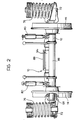
- Figure 2 is an elevational view along the arrow II of Figure 1,
- Figure 3 is a partially-sectioned view taken on the line III-III of Figure 1,
- Figure 4 is a sectional view taken on the line IV-IV of Figure 1,
- Figure 5 illustrates a variant of Figure 1,
- Figure 6 is an elevational view along the arrow VI of Figure 5,
- Figure 7 is a sectional view taken on the line VII-VII of Figure 5, and
- Figure 8 is a section taken on the line VIII-VIII of Figure 1.
- The bogie illustrated in Figures 1 to 4 is substantially analogous to the one described and illustrated in the United States Patent No. 4 362 109 cited above. Briefly, this comprises a
central support structure 10 to which are articulated fourarms 12 each bearing anidle wheel 14. - The
support structure 10, which is obtained in a single piece, for example by the casting of aluminium, comprises a horizontalquadrangular plate 16 having arectangular aperture 18 the larger sides of which are directed parallel to the transverse axis A of the bogie. Within theaperture 18 is inserted a slidingblock 24 of self-lubricating plastics material which has a vertically-elongate parallelepipedal form with a square horizontal section and sides slightly shorter than the smaller sides of theaperture 18. Theblock 24 is mounted in theaperture 18 for sliding along the transverse axis A of the bogie and is also free to make limited movements in theaperture 18 parallel to the longitudinal axis D of the bogie. - The
sliding block 24 has a central cylindrical hole in which avertical articulation pin 28 is rotatably engaged. Thispin 28 is fixed at its upper end to anupper disc 34 intended to be bolted to the base of the body of a railway vehicle, and is clamped at its lower end to a lowerhorizontal disc 46. - Between the
plate 16 and theupper disc 34 on the one hand and thelower disc 46 on the other are clamped respectively a firstannular member 50 of elastomeric material and a secondannular member 52 of elastomeric material, with vertical axes. The function of the elastomericannular members block 24 in theaperture 18 and on the rotations of the bogie about thearticulation pin 28. - The transverse sides of the
plate 16 are connected to a pair of transverse tubular supports 54 within which twoshafts 56 are rotatably mounted. The end of eachshaft 56 project from the respectivetubular support 54 and each supports, through an elastic coupling, one of thearms 12 bearing thewheels 14. Bushes of elastomeric material, not visible in the drawings, usually of the type sold under the trade mark "SUTUCO" by the Italian form SAGA of Milan, are interposed coaxially between each of theshafts 56 and the respectivetubular support 54. The purpose of the bushes of elastomeric material is to permit a misalignment between theshafts 56 and the respectivetubular spacers 88 so as to effect the self-steering of thearms 12 bearing thewheels 14 during travel of the bogie around curves, and to allow rolling oscillations of thesearms 12. In this manner, eachshaft 56 connecting a pair ofarms 12 is subject to simple bending stresses in use, and not to twisting actions. - Supported in a projecting manner at the free end of each
arm 12 is aspindle 68 which, with the interposition of rolling bearings, serves as the support for rotation of therespective wheel 14. Ahorizontal support 72 projects from the free end of eachspindle 68, against which bears ahelical suspension spring 76 intended to react at its upper end against the base of the body of the railway vehicle. The foursprings 76 constitute the only suspension of the bogie: in this way, the structural weight of the body passes directly to thewheels 14 through thesprings 76, without stressing intermediate members. - Connected to the
springs 76 are four vertical hydraulic shock-absorbers, each of which is interposed between the free end of one of thearms 12 and the body of the vehicle. - Each
wheel 14 comprises a one-piece body of hot-rolled steel which has a rim of variable conicity and the outer faces of which co-operate with abrake caliper 82 supported by therespective arm 12. - The bogie also includes a pair of transverse hydraulic shock-
absorbers 84 articulated to the sides of theplate 16 and intended to be connected to the body of the vehicle, and a pair of anti-roll bars, generally indicated 86, which connect the two pairs ofarms 12 supported by the twoshafts 56. - According to the invention, a
tubular spacer member 88 aigned with thespindles 68 of thewheels 14 is interposed between the free ends of the twoarms 12 supported by eachshaft 56. - The two
tubular spacers 88, whose ends are rigidly connected to the ends of thecorresponding arms 12, serve to maintain thewheels 14 at the prescribed gauge, which is advantageous both during the assembly of the bogie and when it is in use. - It should be noted that the connection between the bogie and the body of the railway vehicle could be effected in a manner different from that described with reference to Figures 1 to 4, and particularly by means of indirect connection solutions which allow the
arms 12 to be elastically uncoupled with respect to the body. - One possible solution of this type is illustrated in Figures 5 to 8, in which parts identical or similar to those described previously are indicated by the same reference numerals.
- The bogie illustrated in Figures 5 to 8 differs from that described above with regard to the form of the
central support structure 10, and in that thearms 12 of the two pairs located on the same side of the bogie are articulated to each other in correspondence with their facing ends. In fact, onearm 12 of each pair has alongitudinal appendage 90 which extends towards thearm 12 of the other pair situated on the same side of the bogie and is connected to that arm by means of atransverse pin 92, with the interposition of members of elastomeric material, not shown. - In this case, the central support structure comprises two lateral supports 94 rigid with the tubular supports 54 and defining with them a
space 96 within which extends a vertical-axis bush 98 in which is inserted thearticulation pin 28 for the body. - The upper end of the
pin 28 is integral with frusto-conical attachment member 100 intended to be secured rigidly to the base of the body and the opposing sides of which are connected to thelateral supports 94 by twovertical connecting rods 102. - The
bush 98 is surrounded at its upper end by acollar 104 and at its lower end by acollar 106, with the interposition of respective sleeves of elastically-yieldingmaterial upper collar 104 is connected in turn to the two tubular supports 54 by a pair of substantially horizontal longitudinal connectingrods 112 arranged in a Z-configuration. - The
lower collar 106 has twolateral buffers 114 of elastomeric material directed parallel to the transverse axis A of the bogie and having respective convexly-profiled ends lla facing corresponding convexly-profiled ends 116a of a pair ofsimilar buffers 116 protruding from thelateral supports 94. Each pair ofbuffers helical compression spring 118 reacting between thecollar 106 and the correspondinglateral support 94. - In practice, the
buffers springs 118 constitute a resilient system through which thearms 12 of the bogie are uncoupled with respect to the body. - Naturally, different variants of the system of connection between the bogie of the invention and the body of the railway vehicle may be envisaged, even a type intermediate the direct type and the indirect type described above.
- Moreover, it is clear that the details of construction and the forms of embodiment may be varied widely with respect to what has been described and illustrated, without thereby departing from the scope of the present invention.
Claims (7)
Priority Applications (1)
| Application Number | Priority Date | Filing Date | Title |
|---|---|---|---|
| AT85830240T ATE59022T1 (en) | 1984-10-05 | 1985-09-24 | BOGIE WITH FREE-WHEELING WHEELS FOR RAIL VEHICLES. |
Applications Claiming Priority (2)
| Application Number | Priority Date | Filing Date | Title |
|---|---|---|---|
| IT6799384 | 1984-10-05 | ||
| IT67993/84A IT1182317B (en) | 1984-10-05 | 1984-10-05 | TROLLEY FOR INDEPENDENT WHEEL RAILWAY VEHICLES |
Publications (3)
| Publication Number | Publication Date |
|---|---|
| EP0177460A2 true EP0177460A2 (en) | 1986-04-09 |
| EP0177460A3 EP0177460A3 (en) | 1987-08-26 |
| EP0177460B1 EP0177460B1 (en) | 1990-12-12 |
Family
ID=11307030
Family Applications (1)
| Application Number | Title | Priority Date | Filing Date |
|---|---|---|---|
| EP85830240A Expired - Lifetime EP0177460B1 (en) | 1984-10-05 | 1985-09-24 | Bogie for railway vehicles with independent wheels |
Country Status (4)
| Country | Link |
|---|---|
| EP (1) | EP0177460B1 (en) |
| AT (1) | ATE59022T1 (en) |
| DE (1) | DE3580886D1 (en) |
| IT (1) | IT1182317B (en) |
Cited By (5)
| Publication number | Priority date | Publication date | Assignee | Title |
|---|---|---|---|---|
| EP0334418A1 (en) * | 1988-03-16 | 1989-09-27 | S.p.A. SOCIETA' CASSEFORME METALLICHE E AFFINI S.A.C.M.A. | Bogie for passenger railway carriages with the floor at platform level throughout the carriage |
| EP0363972A3 (en) * | 1988-10-14 | 1990-07-18 | FIAT FERROVIARIA S.p.A. | A self-steering bogie for a railway vehicle |
| EP0802101A3 (en) * | 1996-04-17 | 1999-01-13 | Patentes Talgo, S.A. | Railway axle assembly furnished with automatic change of track gauge and adaptable to conventional freight bogies |
| KR20030054575A (en) * | 2001-12-26 | 2003-07-02 | 한국철도기술연구원 | derailment protective elastic axel of electric train |
| WO2008145641A1 (en) | 2007-05-29 | 2008-12-04 | Bombardier Transportation Gmbh | Rail vehicle with single-stage suspension |
Family Cites Families (4)
| Publication number | Priority date | Publication date | Assignee | Title |
|---|---|---|---|---|
| US2473714A (en) * | 1945-07-03 | 1949-06-21 | Goodrich Co B F | Rail truck suspension |
| DE829602C (en) * | 1950-09-01 | 1952-01-28 | Krauss Maffei Ag | Trunnion guide on the bogie of rail vehicles |
| DE1059494B (en) * | 1956-02-09 | 1959-06-18 | Krauss Maffei Ag | Trunnion mounting for relieved trunnions of rail vehicles |
| IT1118694B (en) * | 1979-05-24 | 1986-03-03 | Fiat Ricerche | TROLLEY FOR RAILWAY VEHICLES |
-
1984
- 1984-10-05 IT IT67993/84A patent/IT1182317B/en active
-
1985
- 1985-09-24 EP EP85830240A patent/EP0177460B1/en not_active Expired - Lifetime
- 1985-09-24 AT AT85830240T patent/ATE59022T1/en not_active IP Right Cessation
- 1985-09-24 DE DE8585830240T patent/DE3580886D1/en not_active Expired - Fee Related
Cited By (9)
| Publication number | Priority date | Publication date | Assignee | Title |
|---|---|---|---|---|
| EP0334418A1 (en) * | 1988-03-16 | 1989-09-27 | S.p.A. SOCIETA' CASSEFORME METALLICHE E AFFINI S.A.C.M.A. | Bogie for passenger railway carriages with the floor at platform level throughout the carriage |
| EP0363972A3 (en) * | 1988-10-14 | 1990-07-18 | FIAT FERROVIARIA S.p.A. | A self-steering bogie for a railway vehicle |
| US5024165A (en) * | 1988-10-14 | 1991-06-18 | Fiat Ferroviaria S.P.A. | Self-steering bogie for a railway vehicle |
| EP0802101A3 (en) * | 1996-04-17 | 1999-01-13 | Patentes Talgo, S.A. | Railway axle assembly furnished with automatic change of track gauge and adaptable to conventional freight bogies |
| ES2130039A2 (en) * | 1996-04-17 | 1999-06-16 | Talgo Patentes | Railway axle assembly furnished with automatic change of track gauge and adaptable to conventional freight bogies |
| KR20030054575A (en) * | 2001-12-26 | 2003-07-02 | 한국철도기술연구원 | derailment protective elastic axel of electric train |
| WO2008145641A1 (en) | 2007-05-29 | 2008-12-04 | Bombardier Transportation Gmbh | Rail vehicle with single-stage suspension |
| DE102007025163A1 (en) | 2007-05-29 | 2008-12-04 | Bombardier Transportation Gmbh | Rail vehicle with single-stage suspension |
| EP2559605A2 (en) | 2007-05-29 | 2013-02-20 | Bombardier Transportation GmbH | Rail vehicle with single-stage suspension |
Also Published As
| Publication number | Publication date |
|---|---|
| IT8467993A1 (en) | 1986-04-05 |
| EP0177460A3 (en) | 1987-08-26 |
| ATE59022T1 (en) | 1990-12-15 |
| IT8467993A0 (en) | 1984-10-05 |
| IT1182317B (en) | 1987-10-05 |
| EP0177460B1 (en) | 1990-12-12 |
| DE3580886D1 (en) | 1991-01-24 |
Similar Documents
| Publication | Publication Date | Title |
|---|---|---|
| US4848789A (en) | Vehicle chassis tranverse structural member | |
| US6250232B1 (en) | Running gear for a rail vehicle | |
| US4735149A (en) | Railway vehicle suspension | |
| US4930804A (en) | Independent wheel suspension for motor vehicles | |
| US4589677A (en) | Suspension for a rigid axle for vehicles | |
| CZ290731B6 (en) | Axle suspension for rigid axles in vehicles | |
| US3804433A (en) | Wheel suspension for vehicles | |
| US5327837A (en) | Bolster of a railroad car truck with varying cross-sectional shape to provide less torsional rigidity at ends | |
| US6074016A (en) | Flexible axle embodying a crosspiece and trailing arms | |
| US20050183625A1 (en) | High efficiency semi-articulated railway power bogie | |
| US2689015A (en) | Axle suspension for motor vehicles | |
| JP2655730B2 (en) | Railcar | |
| CA2061994C (en) | Bogies for rail vehicles | |
| EP0189382A2 (en) | High-speed railway vehicle with a variable-attitude body | |
| EP0052639B1 (en) | Axle construction for vehicle | |
| EP0177460B1 (en) | Bogie for railway vehicles with independent wheels | |
| US5943959A (en) | Partially sprung drive, in particular for electric traction vehicles | |
| EP0277929A1 (en) | Bogie arrangement for a railway vehicle | |
| EP0354189B1 (en) | A transverse suspension for railway vehicles | |
| JP3498258B2 (en) | 2-axle bogie for railway vehicles | |
| EP0265682B1 (en) | Device for motor-car suspensions | |
| US4355696A (en) | Axle suspension for the driven axle of a road vehicle | |
| EP0045411A2 (en) | Equalized four-spring tandem axle suspension | |
| EP0098812B1 (en) | Independent wheel suspension for motor vehicles | |
| SU1682227A1 (en) | Four-wheel rail vehicle |
Legal Events
| Date | Code | Title | Description |
|---|---|---|---|
| PUAI | Public reference made under article 153(3) epc to a published international application that has entered the european phase |
Free format text: ORIGINAL CODE: 0009012 |
|
| AK | Designated contracting states |
Kind code of ref document: A2 Designated state(s): AT BE CH DE FR GB IT LI LU NL SE |
|
| PUAL | Search report despatched |
Free format text: ORIGINAL CODE: 0009013 |
|
| AK | Designated contracting states |
Kind code of ref document: A3 Designated state(s): AT BE CH DE FR GB IT LI LU NL SE |
|
| 17P | Request for examination filed |
Effective date: 19870807 |
|
| 17Q | First examination report despatched |
Effective date: 19890405 |
|
| GRAA | (expected) grant |
Free format text: ORIGINAL CODE: 0009210 |
|
| AK | Designated contracting states |
Kind code of ref document: B1 Designated state(s): AT BE CH DE FR GB IT LI LU NL SE |
|
| REF | Corresponds to: |
Ref document number: 59022 Country of ref document: AT Date of ref document: 19901215 Kind code of ref document: T |
|
| ITF | It: translation for a ep patent filed | ||
| ET | Fr: translation filed | ||
| REF | Corresponds to: |
Ref document number: 3580886 Country of ref document: DE Date of ref document: 19910124 |
|
| PLBE | No opposition filed within time limit |
Free format text: ORIGINAL CODE: 0009261 |
|
| STAA | Information on the status of an ep patent application or granted ep patent |
Free format text: STATUS: NO OPPOSITION FILED WITHIN TIME LIMIT |
|
| 26N | No opposition filed | ||
| ITTA | It: last paid annual fee | ||
| EPTA | Lu: last paid annual fee | ||
| EAL | Se: european patent in force in sweden |
Ref document number: 85830240.9 |
|
| PGFP | Annual fee paid to national office [announced via postgrant information from national office to epo] |
Ref country code: LU Payment date: 19950801 Year of fee payment: 11 |
|
| PGFP | Annual fee paid to national office [announced via postgrant information from national office to epo] |
Ref country code: CH Payment date: 19950814 Year of fee payment: 11 Ref country code: AT Payment date: 19950814 Year of fee payment: 11 |
|
| PGFP | Annual fee paid to national office [announced via postgrant information from national office to epo] |
Ref country code: GB Payment date: 19950815 Year of fee payment: 11 |
|
| PGFP | Annual fee paid to national office [announced via postgrant information from national office to epo] |
Ref country code: NL Payment date: 19950817 Year of fee payment: 11 |
|
| PGFP | Annual fee paid to national office [announced via postgrant information from national office to epo] |
Ref country code: SE Payment date: 19950821 Year of fee payment: 11 |
|
| PGFP | Annual fee paid to national office [announced via postgrant information from national office to epo] |
Ref country code: DE Payment date: 19950823 Year of fee payment: 11 |
|
| PGFP | Annual fee paid to national office [announced via postgrant information from national office to epo] |
Ref country code: BE Payment date: 19950824 Year of fee payment: 11 |
|
| PGFP | Annual fee paid to national office [announced via postgrant information from national office to epo] |
Ref country code: FR Payment date: 19950929 Year of fee payment: 11 |
|
| PG25 | Lapsed in a contracting state [announced via postgrant information from national office to epo] |
Ref country code: LU Free format text: LAPSE BECAUSE OF NON-PAYMENT OF DUE FEES Effective date: 19960924 Ref country code: GB Effective date: 19960924 Ref country code: AT Effective date: 19960924 |
|
| PG25 | Lapsed in a contracting state [announced via postgrant information from national office to epo] |
Ref country code: SE Effective date: 19960925 |
|
| PG25 | Lapsed in a contracting state [announced via postgrant information from national office to epo] |
Ref country code: LI Effective date: 19960930 Ref country code: FR Effective date: 19960930 Ref country code: CH Effective date: 19960930 Ref country code: BE Effective date: 19960930 |
|
| BERE | Be: lapsed |
Owner name: FIAT FERROVIARIA SAVIGLIANO S.P.A. Effective date: 19960930 |
|
| PG25 | Lapsed in a contracting state [announced via postgrant information from national office to epo] |
Ref country code: NL Effective date: 19970401 |
|
| GBPC | Gb: european patent ceased through non-payment of renewal fee |
Effective date: 19960924 |
|
| REG | Reference to a national code |
Ref country code: CH Ref legal event code: PL |
|
| NLV4 | Nl: lapsed or anulled due to non-payment of the annual fee |
Effective date: 19970401 |
|
| PG25 | Lapsed in a contracting state [announced via postgrant information from national office to epo] |
Ref country code: DE Effective date: 19970603 |
|
| EUG | Se: european patent has lapsed |
Ref document number: 85830240.9 |
|
| REG | Reference to a national code |
Ref country code: FR Ref legal event code: ST |
|
| REG | Reference to a national code |
Ref country code: FR Ref legal event code: ST |