EP0176127A1 - Lens mounting for and electrodynamic device for recording on and/or scanning optical discs by means of a radiation spot, and method of manufacturing such a lens mounting - Google Patents
Lens mounting for and electrodynamic device for recording on and/or scanning optical discs by means of a radiation spot, and method of manufacturing such a lens mounting Download PDFInfo
- Publication number
- EP0176127A1 EP0176127A1 EP85201404A EP85201404A EP0176127A1 EP 0176127 A1 EP0176127 A1 EP 0176127A1 EP 85201404 A EP85201404 A EP 85201404A EP 85201404 A EP85201404 A EP 85201404A EP 0176127 A1 EP0176127 A1 EP 0176127A1
- Authority
- EP
- European Patent Office
- Prior art keywords
- lens mounting
- moulding
- lens
- die
- connecting means
- Prior art date
- Legal status (The legal status is an assumption and is not a legal conclusion. Google has not performed a legal analysis and makes no representation as to the accuracy of the status listed.)
- Granted
Links
- 230000003287 optical effect Effects 0.000 title claims abstract description 21
- 230000005855 radiation Effects 0.000 title claims abstract description 18
- 230000005520 electrodynamics Effects 0.000 title claims abstract description 12
- 238000004519 manufacturing process Methods 0.000 title claims description 15
- 238000001746 injection moulding Methods 0.000 claims abstract description 4
- 238000000465 moulding Methods 0.000 claims description 37
- 238000000034 method Methods 0.000 claims description 8
- 239000000463 material Substances 0.000 claims description 6
- 229920001187 thermosetting polymer Polymers 0.000 claims description 6
- 239000004033 plastic Substances 0.000 claims description 4
- 229920003023 plastic Polymers 0.000 claims description 4
- 238000002347 injection Methods 0.000 claims description 3
- 239000007924 injection Substances 0.000 claims description 3
- 230000005291 magnetic effect Effects 0.000 description 3
- 238000006073 displacement reaction Methods 0.000 description 2
- KXGFMDJXCMQABM-UHFFFAOYSA-N 2-methoxy-6-methylphenol Chemical compound [CH]OC1=CC=CC([CH])=C1O KXGFMDJXCMQABM-UHFFFAOYSA-N 0.000 description 1
- OKTJSMMVPCPJKN-UHFFFAOYSA-N Carbon Chemical compound [C] OKTJSMMVPCPJKN-UHFFFAOYSA-N 0.000 description 1
- 239000000853 adhesive Substances 0.000 description 1
- 230000001070 adhesive effect Effects 0.000 description 1
- XAGFODPZIPBFFR-UHFFFAOYSA-N aluminium Chemical compound [Al] XAGFODPZIPBFFR-UHFFFAOYSA-N 0.000 description 1
- 229910052782 aluminium Inorganic materials 0.000 description 1
- 239000004411 aluminium Substances 0.000 description 1
- 239000004020 conductor Substances 0.000 description 1
- 230000005294 ferromagnetic effect Effects 0.000 description 1
- 239000011152 fibreglass Substances 0.000 description 1
- 230000004907 flux Effects 0.000 description 1
- 229910002804 graphite Inorganic materials 0.000 description 1
- 239000010439 graphite Substances 0.000 description 1
- 239000005011 phenolic resin Substances 0.000 description 1
- 229920001568 phenolic resin Polymers 0.000 description 1
Images

Classifications
-
- G—PHYSICS
- G11—INFORMATION STORAGE
- G11B—INFORMATION STORAGE BASED ON RELATIVE MOVEMENT BETWEEN RECORD CARRIER AND TRANSDUCER
- G11B7/00—Recording or reproducing by optical means, e.g. recording using a thermal beam of optical radiation by modifying optical properties or the physical structure, reproducing using an optical beam at lower power by sensing optical properties; Record carriers therefor
- G11B7/12—Heads, e.g. forming of the optical beam spot or modulation of the optical beam
- G11B7/22—Apparatus or processes for the manufacture of optical heads, e.g. assembly
-
- G—PHYSICS
- G11—INFORMATION STORAGE
- G11B—INFORMATION STORAGE BASED ON RELATIVE MOVEMENT BETWEEN RECORD CARRIER AND TRANSDUCER
- G11B7/00—Recording or reproducing by optical means, e.g. recording using a thermal beam of optical radiation by modifying optical properties or the physical structure, reproducing using an optical beam at lower power by sensing optical properties; Record carriers therefor
- G11B7/08—Disposition or mounting of heads or light sources relatively to record carriers
-
- Y—GENERAL TAGGING OF NEW TECHNOLOGICAL DEVELOPMENTS; GENERAL TAGGING OF CROSS-SECTIONAL TECHNOLOGIES SPANNING OVER SEVERAL SECTIONS OF THE IPC; TECHNICAL SUBJECTS COVERED BY FORMER USPC CROSS-REFERENCE ART COLLECTIONS [XRACs] AND DIGESTS
- Y10—TECHNICAL SUBJECTS COVERED BY FORMER USPC
- Y10S—TECHNICAL SUBJECTS COVERED BY FORMER USPC CROSS-REFERENCE ART COLLECTIONS [XRACs] AND DIGESTS
- Y10S359/00—Optical: systems and elements
- Y10S359/90—Methods
Definitions
- the invention relates to a movable lens mounting for an electrodynamic device for recording on and/or scanning optical discs by means of a radiation spot, which device comprises a frame with supporting means for guiding the lens mounting, which lens mounting comprises a first part which cooperates with said supporting means and a second part which is movable relative to the first part and which comprises a mount for a lens system for focussing a radiation beam, and connecting means which movably connect the first part and the second part to each other.
- the invention also relates to a method of manufacturing a movable lens mounting for an electrodynamic device for recording on and/ or scanning optical discs by means of a radiation spot, which device comprises a frame with supporting means for guiding the lens mounting, which lens mounting comprises a first part which cooperates with said supporting means and a second part which is movable relative to the first part and which conprises a mount for a lens system for focussing a radiation beam, and connecting means which movably connect the first part and the second part to each other.
- the known lens mounting is used in an electrodynamic device in which the lens system is translated along a radial path relative to an optically readable disc which is rotatable about an axis of rotation.
- the supporting means of the frame comprise two guide rods along which the lens mounting can be translated by means of sleeve bearings arranged on the first part of the lens mounting.
- the frame also comprises two stator magnets which extend parallel to the guide rods, two actuator coils being arranged on the first part of the lens mounting in the field of these magnets.
- the second part of the lens mounting carries the lens system whose optical axis extends transversely of the optically readable disc.
- the second part of the lens mounting together with the lens system is movable relative to the first part along the optical axis.
- the second part is movably mounted relative to the first part by means of two pairs of blade springs which are secured to the first part and to the second part of the lens mounting with the aid of bolts.
- actuator coils are arranged, which coils cooperate with said stator magnets and which provide the electrodynamic drive of the second part along the optical axis of the lens system.
- the invention aims at providing a lens mounting and a method of the kind defined in the opening paragraphs, which do not have the above disadvantages.
- the lens mounting is characterized in that the connecting means are embedded in the first and the second part of the lens mounting by injection-moulding.
- An advantage of the lens mounting in accordance with the invention is that the first part and the second part of the lens mounting are positioned relative to each other in a sinple and reproducible manner. Moreover, in comparison with the known lens mounting the novel lens mounting is substantially cheaper. This is mainly due to the smaller number of operations to be carried out during manufacture of the lens mounting.
- a suitable embodiment of the invention is characterized in that the connecting means comprise at least two parallel blade springs Which are situated at different levels relative to each other, said blade springs being embedded in the first part of the lens mounting at one end and in the second part of said mounting at the other end.
- a further suitable embodiment is characterized in that portions of the blade springs which are situated between and at some distance from the first and the second part are encapsulated in a plastics.
- the stiffness of the springs in their axial directions and hence the stiffness of the lens mounting in its direction of translation or, which corresponds to the same thing, in a radial direction relative to the optically readable disc is increased substantially, whilst the elasticity of the blade springs in their transverse direction is not changed significantly.
- Said increased stiffness has the advantange that the lens mounting is deformed to a smaller extent when forces are applied between the first and the second part, which leads to an increased bandwidth of the control loop for the lens system and consequently to an improved dynamic performance of the device.
- the position of the first part and the second part of the lens mounting relative to each other is defined entirely by the relevant moulding portions in the moulding die.
- the method in accordance with the invention is very suitable for mechanization, enabling the mass production of cheap lens mountings of accurate dimensions by means of one accurately manufactured moulding die.
- the method is characterized in that the connecting means comprise at least two blade springs which are arranged parallel to each other and at different levels in the moulding die, after which during the injection of the thermosetting material into the moulding die one and of each of the blade springs is embedded in the first part and the other end in the second part.
- the blade springs can be supported in the moulding die by wall portions of the moulding die which thus constitute the supporting provisions.
- the electrodynamic device sham in Figs. 1 and 2 serves for recording and/or reading information in/from an information surface of an optical disc 5, which rotates about an axis of rotation 3, by means of a radiation beam 1.
- the device comprises a frame 7 and a lens mounting 11 which can be translated relative to the frame along a radial path 9 and which carries a lens system 13 comprising at least one lens.
- the frame 7 carries two permanent stator magnets 15A and 15B, which extend parallel to the path 9 and which are magnetized transversely to said path in a direction indicated by arrows.
- Two actuator coils 17A and 17B of an electrically conductive material can be translated in the magnetic field of the stator magnets 15A and 15B.
- the frame 7 carries bearing means for the lens mounting 11 in the form of two guide rods 19A and 19B whose free ends are secured to the frame 7 by means of members 21 and bolts 23.
- the guide rods 19A and 19B form part of a stator yoke with an air gap 25A between the magnet 15A and the rod 19A and an air gap 25B between the magnet 15B and the rod 19B.
- the actuator coils 17A and 17B are arranged around the guide rods 19A and 19B, respectively.
- the lens mounting 11 (see also Figs. 3 and 4) comprises a first part 27 to which the coils 17A and 17B are secured and which carprises supporting surfaces 29 which cooperate with the guide rods 19A and 19B.
- the first part 27 also has a 45° surface 34 for mounting a reflecting element.
- the lens mounting further comprises a second part 31 ccnprising a lens mount 32 for the lens system 13.
- the second part 31 is movably connected to the first part 27 by connecting means comprising three blade springs 33A, 33B and 35.
- the blade spring 35 is situated at the upper side of the lens mounting 11 and extends parallel to two adjacently arranged blade springs 33A and 33B which are situated at the lower side of the lens mounting 11.
- the ends 37 and 39 of the blade springs 33A, 33B and 35 are embedded in the first part 27 and the second part 31, respectively of the lens mounting 11.
- a part 41 of their length has been coated with a plastics.
- the lens system 13 is secured to the second part 31 of the lens mounting 11 and is movable along its optical axis 43 in order to enable the movements of the information disc 5 to be followed with a radiation spot 45 formed by the radiation beam 1 produced by a suitable radiation source 46, shown schematically.
- the blade springs 33A, 33B and 35 allow a limited displacement of the second part 31 along the optical axis 43.
- the second part 31 of the lens mounting 11 is driven by two actuator coils 47a and 47b which are secured to projections 48 formed for this purpose on opposite sides of the lens mounting.
- stator coils 47A and 47B are movable in said air gaps 25A and 25B, so that the actuator coils 47A and 47B cooperate with the field of the stator magnets 15A and 15B to subject the lens system 13 to forces which are directed along the optical axis 43.
- the frame 7 is shaped sudstantially as an open box with a bottom 49 and upright walls 51, 52, 53 and 54.
- the upright walls may be made of aluminium or a plastics and are interconnected at the corners.
- the stator magnets 19A and 19B are secured to the inner sides of the walls 51 and 52, for example by means of a suitable adhesive.
- the magnetic lines of force of the magnets 15A and 15B extend through the air gaps 25A and 26B towards the guide rods 19A and 19B, the path for the magnetic flux being closed by ferromagnetic strips 56 which are secured to the inner sides of the walls 51, 52, 53 and 54.
- the wall 53 has an opening 55 for securing the housing of the radiation source 46.
- the beam 1 which issues from the radiation source 46 is reflected at an angle of 90° by a reflecting element 57 which is mounted on the 45° surface 34 at the underside of the lens mounting 11.
- the connecting wires to the coils, the other electrical connections and the means necessary for detecting the position of the lens system are not shown for the sake of simplicity, because they are irrelevant to the present invention.
- the method in accordance with the invention will now be described in more detail with reference to Figs. 5, 6 and 7.
- the moulding die 61 in principle comprises two separable die sections, in the present exanple the first die section 63 and the second die section 65.
- the facing sides 63A and 65A of the die sections 63 and 65, respectively are formed with a plurality of moulding portions which, when the die 61 is closed, enclose a cavity whose contours 67 (partly indicated by broken lines) correspond to those of the lens mounting to be formed.
- the moulding portions 69 and the moulding portions 71 for moulding the supporting surfaces and the lens mount are arranged in the same die section 63.
- the die sections 63 and 65 comprise a plurality of parts. For the sake of simplicity all these parts are not shown. Fig 5, for example, only shows that the die 63 comprises an insert 73 and a pin 75.
- the die section 63 comprises a plurality of supporting surfaces 77 for supporting the ends of the blade springs to be embedded.
- the die 61 is open three blade springs are arranged on said supporting surfaces 77, after which the die is closed by moving the die sections 63 and 65 towards one another.
- the die is now ready for moulding a lens mounting in accordance with the invention.
- a thermosetting material for example phenolic resin with 30 % of fibre glass and 10 % of graphite, is injected into the moulding cavity via supply pipes 79, the lens mounting with embedded and encapsulated blade springs being formed as the cavity is filled.
Landscapes
- Physics & Mathematics (AREA)
- Optics & Photonics (AREA)
- Optical Recording Or Reproduction (AREA)
- Mechanical Optical Scanning Systems (AREA)
- Moulds For Moulding Plastics Or The Like (AREA)
- Optical Head (AREA)
- Lens Barrels (AREA)
Abstract
Description
- The invention relates to a movable lens mounting for an electrodynamic device for recording on and/or scanning optical discs by means of a radiation spot, which device comprises a frame with supporting means for guiding the lens mounting, which lens mounting comprises a first part which cooperates with said supporting means and a second part which is movable relative to the first part and which comprises a mount for a lens system for focussing a radiation beam, and connecting means which movably connect the first part and the second part to each other.
- The invention also relates to a method of manufacturing a movable lens mounting for an electrodynamic device for recording on and/ or scanning optical discs by means of a radiation spot, which device comprises a frame with supporting means for guiding the lens mounting, which lens mounting comprises a first part which cooperates with said supporting means and a second part which is movable relative to the first part and which conprises a mount for a lens system for focussing a radiation beam, and connecting means which movably connect the first part and the second part to each other.
- Such a lens mounting and method of manufacturing a lens mounting are disclosed in Netherlands Patent Application 8204366.
- The known lens mounting is used in an electrodynamic device in which the lens system is translated along a radial path relative to an optically readable disc which is rotatable about an axis of rotation. The supporting means of the frame comprise two guide rods along which the lens mounting can be translated by means of sleeve bearings arranged on the first part of the lens mounting. The frame also comprises two stator magnets which extend parallel to the guide rods, two actuator coils being arranged on the first part of the lens mounting in the field of these magnets. The second part of the lens mounting carries the lens system whose optical axis extends transversely of the optically readable disc. The second part of the lens mounting together with the lens system is movable relative to the first part along the optical axis. The said translation of the lens mounting and the movement of the second part of said mounting along the optical axis are necessary to enable the movements of the optical disc to be followed with a radiation beam which is formed into a radiation spot by the lens system.
- In the known lens mounting the second part is movably mounted relative to the first part by means of two pairs of blade springs which are secured to the first part and to the second part of the lens mounting with the aid of bolts. On opposite sides of the second part actuator coils are arranged, which coils cooperate with said stator magnets and which provide the electrodynamic drive of the second part along the optical axis of the lens system.
- During the manufacture of a lens system of the type defined above it is essential that the two parts of the lens mounting are positioned accurately relative to each other in order to ensure that the optical axis of the lens system of the lens mounting when incorporated in an electrodynamic device is perpendicular to the recording surface of the optical disc. A misalignment may result in an oblique position of the optical axis of the lens system relative to the recording surface of the optical disc, which causes a change in the light spot which is imaged on the recording surface. During manufacture of the lens noun- ting it is therefore necessary to position the second part accurately relative to the first part, after which the two parts are secured to each other by means of bolts. In particular, these operations are labour intensive and consequently increase cost in mass production.
- The invention aims at providing a lens mounting and a method of the kind defined in the opening paragraphs, which do not have the above disadvantages.
- According to the invention the lens mounting is characterized in that the connecting means are embedded in the first and the second part of the lens mounting by injection-moulding.
- An advantage of the lens mounting in accordance with the invention is that the first part and the second part of the lens mounting are positioned relative to each other in a sinple and reproducible manner. Moreover, in comparison with the known lens mounting the novel lens mounting is substantially cheaper. This is mainly due to the smaller number of operations to be carried out during manufacture of the lens mounting.
- A suitable embodiment of the invention is characterized in that the connecting means comprise at least two parallel blade springs Which are situated at different levels relative to each other, said blade springs being embedded in the first part of the lens mounting at one end and in the second part of said mounting at the other end. By thus arranging the blade springs, which is known per se, and securing the blade springs through injection-moulding a suitable displacement of the lens mounting along the optical axis of the lens system is possible without friction and lost motion.
- A further suitable embodiment is characterized in that portions of the blade springs which are situated between and at some distance from the first and the second part are encapsulated in a plastics.
- Advantageously in this embodiment the stiffness of the springs in their axial directions and hence the stiffness of the lens mounting in its direction of translation or, which corresponds to the same thing, in a radial direction relative to the optically readable disc is increased substantially, whilst the elasticity of the blade springs in their transverse direction is not changed significantly. Said increased stiffness has the advantange that the lens mounting is deformed to a smaller extent when forces are applied between the first and the second part, which leads to an increased bandwidth of the control loop for the lens system and consequently to an improved dynamic performance of the device.
- The method in accordance with the invention is characterized in that it comprises the following steps:
- The manufacture of a moulding die which comprises a plurality of die sections and provided with at least moulding portions for molding the first part and the second part of the lens mounting, and provisions for supporting the connecting means, at least the moulding portions for moulding the portions of the first part which cooperate with the supporting means and for moulding the lens mount in the second part of the lens mounting being located in one die section,
- arranging the connecting means in the moulding die, and
- closing the moulding die and subsequently manufacturing the lens mounting and simultaneously embedding the connecting means therein by injecting a thermosetting material into the moulding die.
- In the method in accordance with the invention the position of the first part and the second part of the lens mounting relative to each other is defined entirely by the relevant moulding portions in the moulding die. An advantage of this is that during injection of the thermosetting material into the moulding die the first part and the second part of the lens mounting are formed and connected to each other in an accurately defined position relative to each other, in particular the portion of the first part of the lens mounting and that portion of the second part which constitutes the lens mount occupying an exact position relative to each other without any additional operations being required.
- The method in accordance with the invention is very suitable for mechanization, enabling the mass production of cheap lens mountings of accurate dimensions by means of one accurately manufactured moulding die.
- Suitably, the method is characterized in that the connecting means comprise at least two blade springs which are arranged parallel to each other and at different levels in the moulding die, after which during the injection of the thermosetting material into the moulding die one and of each of the blade springs is embedded in the first part and the other end in the second part.
- The blade springs can be supported in the moulding die by wall portions of the moulding die which thus constitute the supporting provisions.
- The invention will now be described in more detail, by way of example, with reference to the drawings, in which:
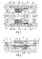
- Fig. 1 is a plan view of an embodiment of the invention, incorporated in an electrodynamic device, shown schematically,
- Fig. 2 shows the electrodynamic device provided with an optically readable disc in a longitudinal sectional view taken on the lines II - II in Fig. 1,
- Fig. 3 is an underneath view of the lens mounting shown in Fig. 1,
- Fig. 4 is a longitudinal sectional view taken on the lines IV - IV in Fig. 3,
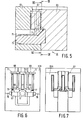
- Fig. 5 is a sectional view of a moulding die for the manufacture of the lens mounting shown in the preceding Figures,
- Fig. 6 is a sectional view taken on the lines VI - VI in Fig. 5, and
- Fig. 7 is a sectional view taken on the lines VII - VII in Fig. 5.
- The electrodynamic device sham in Figs. 1 and 2 serves for recording and/or reading information in/from an information surface of an
optical disc 5, which rotates about an axis of rotation 3, by means of aradiation beam 1. The device comprises aframe 7 and alens mounting 11 which can be translated relative to the frame along a radial path 9 and which carries alens system 13 comprising at least one lens. Theframe 7 carries twopermanent stator magnets actuator coils stator magnets - The
frame 7 carries bearing means for the lens mounting 11 in the form of twoguide rods frame 7 by means ofmembers 21 andbolts 23. Theguide rods air gap 25A between themagnet 15A and therod 19A and anair gap 25B between themagnet 15B and therod 19B. Theactuator coils guide rods - The lens mounting 11 (see also Figs. 3 and 4) comprises a
first part 27 to which thecoils carprises supporting surfaces 29 which cooperate with theguide rods first part 27 also has a 45°surface 34 for mounting a reflecting element. The lens mounting further comprises asecond part 31 ccnprising alens mount 32 for thelens system 13. Thesecond part 31 is movably connected to thefirst part 27 by connecting means comprising threeblade springs blade spring 35 is situated at the upper side of the lens mounting 11 and extends parallel to two adjacently arrangedblade springs ends blade springs first part 27 and thesecond part 31, respectively of the lens mounting 11. In order to increase the axial stiffness of theblade springs part 41 of their length has been coated with a plastics. - The
lens system 13 is secured to thesecond part 31 of thelens mounting 11 and is movable along itsoptical axis 43 in order to enable the movements of theinformation disc 5 to be followed with aradiation spot 45 formed by theradiation beam 1 produced by asuitable radiation source 46, shown schematically. The blade springs 33A, 33B and 35 allow a limited displacement of thesecond part 31 along theoptical axis 43. Thesecond part 31 of thelens mounting 11 is driven by two actuator coils 47a and 47b which are secured toprojections 48 formed for this purpose on opposite sides of the lens mounting. The upper parts of thestator coils air gaps actuator coils stator magnets lens system 13 to forces which are directed along theoptical axis 43. - The
frame 7 is shaped sudstantially as an open box with abottom 49 andupright walls stator magnets walls magnets air gaps 25A and 26B towards theguide rods ferromagnetic strips 56 which are secured to the inner sides of thewalls - The
wall 53 has anopening 55 for securing the housing of theradiation source 46. Thebeam 1 which issues from theradiation source 46 is reflected at an angle of 90° by a reflectingelement 57 which is mounted on the 45°surface 34 at the underside of the lens mounting 11. The connecting wires to the coils, the other electrical connections and the means necessary for detecting the position of the lens system are not shown for the sake of simplicity, because they are irrelevant to the present invention. - The method in accordance with the invention will now be described in more detail with reference to Figs. 5, 6 and 7. By means of this method the lens mounting 11 or a similar lens mounting is manufactured in a multi-section moulding die 61. The moulding die 61 in principle comprises two separable die sections, in the present exanple the
first die section 63 and thesecond die section 65. The facingsides 63A and 65A of thedie sections moulding portions 69 and themoulding portions 71 for moulding the supporting surfaces and the lens mount, respectively are arranged in thesame die section 63. - For reasons of production engineering the
die sections die 63 comprises aninsert 73 and apin 75. - The
die section 63 comprises a plurality of supportingsurfaces 77 for supporting the ends of the blade springs to be embedded. When the die 61 is open three blade springs are arranged on said supportingsurfaces 77, after which the die is closed by moving thedie sections supply pipes 79, the lens mounting with embedded and encapsulated blade springs being formed as the cavity is filled.
Claims (5)
the lens mounting and simultaneously embedding the connecting means therein by injecting a thermosetting material into the moulding die.
Applications Claiming Priority (2)
| Application Number | Priority Date | Filing Date | Title |
|---|---|---|---|
| NL8402777 | 1984-09-12 | ||
| NL8402777A NL8402777A (en) | 1984-09-12 | 1984-09-12 | LENS CARRIER FOR THE USE OF AN ELECTRODYNAMIC DEVICE FOR IRRADICATION AND / OR SCANNING OF OPTICAL PLATES, AND A METHOD FOR MANUFACTURING A LENS CARRIER. |
Publications (2)
| Publication Number | Publication Date |
|---|---|
| EP0176127A1 true EP0176127A1 (en) | 1986-04-02 |
| EP0176127B1 EP0176127B1 (en) | 1989-11-29 |
Family
ID=19844447
Family Applications (1)
| Application Number | Title | Priority Date | Filing Date |
|---|---|---|---|
| EP85201404A Expired EP0176127B1 (en) | 1984-09-12 | 1985-09-06 | Lens mounting for and electrodynamic device for recording on and/or scanning optical discs by means of a radiation spot, and method of manufacturing such a lens mounting |
Country Status (8)
| Country | Link |
|---|---|
| US (1) | US4798447A (en) |
| EP (1) | EP0176127B1 (en) |
| JP (2) | JPS6177147A (en) |
| KR (1) | KR930002159B1 (en) |
| DE (1) | DE3574516D1 (en) |
| HK (1) | HK87991A (en) |
| NL (1) | NL8402777A (en) |
| SG (1) | SG88590G (en) |
Cited By (4)
| Publication number | Priority date | Publication date | Assignee | Title |
|---|---|---|---|---|
| FR2648241A1 (en) * | 1989-06-12 | 1990-12-14 | Aerospatiale | DEVICE FOR GUIDING AND MANEUVERING A MOBILE ELEMENT PARALLEL TO AN AXIS, AND OPTICAL INSTRUMENT COMPRISING SAME |
| EP0410715A3 (en) * | 1989-07-25 | 1993-03-03 | Kabushiki Kaisha Toshiba | Leaf spring mechanism and method of manufacturing the same |
| EP2987835A1 (en) | 2014-08-22 | 2016-02-24 | Evonik Degussa GmbH | Hybrid curing of aqueous silane systems |
| EP2987836A1 (en) | 2014-08-22 | 2016-02-24 | Evonik Degussa GmbH | Hybrid curing of aqueous silane systems |
Families Citing this family (11)
| Publication number | Priority date | Publication date | Assignee | Title |
|---|---|---|---|---|
| US4922477A (en) * | 1987-05-30 | 1990-05-01 | Nec Home Electronics Ltd. | Optical head unit |
| US5046821A (en) * | 1988-11-02 | 1991-09-10 | Nec Corporation | Optics support for an optical disk drive |
| JPH0323523A (en) * | 1989-06-21 | 1991-01-31 | Sony Corp | Optical head device |
| EP0486275B1 (en) * | 1990-11-14 | 1997-05-14 | Canon Kabushiki Kaisha | Objective lens driver |
| DE69228576T2 (en) * | 1991-07-25 | 1999-08-26 | Canon K.K. | Method for magneto-optical data recording or reproduction with a floating vent for carrying a magnetic head and device therefor |
| DE69228279T2 (en) * | 1991-08-30 | 1999-07-08 | Canon K.K., Tokio/Tokyo | Magneto-optical disk device with a floating magnetic head |
| US5463612A (en) * | 1991-12-05 | 1995-10-31 | Canon Kabushiki Kaisha | Objective lens drive apparatus used in optical information recording/reproducing apparatus |
| US5625607A (en) * | 1992-02-13 | 1997-04-29 | Canon Kabushiki Kaisha | Magneto-optical disk apparatus including two magnetic field applying devices, one of which has a substantial ring-shaped core member with a gap in a portion thereof |
| TW239211B (en) * | 1993-04-02 | 1995-01-21 | Hyundai Electronics America | Electromagnetic lens actuator for optical disk drive |
| JP2762930B2 (en) * | 1994-06-14 | 1998-06-11 | 日本電気株式会社 | Thin inner and outer circumference access optical head |
| DE102005010868A1 (en) * | 2005-03-07 | 2006-09-14 | Deutsche Thomson-Brandt Gmbh | Scanner for optical storage media |
Citations (4)
| Publication number | Priority date | Publication date | Assignee | Title |
|---|---|---|---|---|
| US3762847A (en) * | 1971-09-15 | 1973-10-02 | Gen Electric | Apparatus for making a molded electrical structure |
| EP0112595A1 (en) * | 1982-12-24 | 1984-07-04 | Koninklijke Philips Electronics N.V. | Electrodynamic device for translating an objective |
| EP0114082A2 (en) * | 1983-01-14 | 1984-07-25 | Koninklijke Philips Electronics N.V. | Apparatus for recording and/or reading information by means of a radiation beam |
| EP0143356A2 (en) * | 1983-10-31 | 1985-06-05 | Hitachi, Ltd. | Optical system drive for optical recording/reproducing apparatus |
Family Cites Families (14)
| Publication number | Priority date | Publication date | Assignee | Title |
|---|---|---|---|---|
| GB538324A (en) * | 1939-07-25 | 1941-07-29 | Kodak Ltd | Improvements in or relating to the mounting of lenses |
| US2288899A (en) * | 1940-01-15 | 1942-07-07 | Gits Molding Corp | Method of and means for making coaxial cables |
| US3334409A (en) * | 1964-09-01 | 1967-08-08 | Honeywell Inc | Method of flexure mounting print hammers |
| US3476851A (en) * | 1964-12-21 | 1969-11-04 | Carlo Camossi | Method for making vibration dampening and shock absorbing support |
| US3542328A (en) * | 1969-02-19 | 1970-11-24 | Western Electric Co | Mold having v-shaped guides to prevent pinching a lead on a component during an encapsulation process |
| JPS5222246A (en) * | 1976-08-11 | 1977-02-19 | Matsuyama Seisakusho:Kk | Mold for fitting mirror holder to ball section of stay of back-mirror via ball joint |
| US4154506A (en) * | 1976-08-12 | 1979-05-15 | Izon Corporation | Projection lens plate for microfiche |
| JPS5465761A (en) * | 1977-11-04 | 1979-05-26 | Yoshida Kogyo Kk | Method of molding plastic container |
| JPS56168609A (en) * | 1980-05-30 | 1981-12-24 | Ricoh Co Ltd | Platelike lens aggregate |
| JPS5794706A (en) * | 1980-12-04 | 1982-06-12 | Ricoh Co Ltd | Plate-like lens |
| US4472024A (en) * | 1981-01-07 | 1984-09-18 | Olympus Optical Co. Ltd. | Apparatus for driving objective lens |
| JPS58194177A (en) * | 1982-05-07 | 1983-11-12 | Matsushita Electric Ind Co Ltd | Information processing device |
| JPS59148151A (en) * | 1983-02-14 | 1984-08-24 | Olympus Optical Co Ltd | Information track reader |
| US4504935A (en) * | 1983-02-14 | 1985-03-12 | U.S. Philips Corporation | Electrodynamic focus and radial slide drive for an optical disc system |
-
1984
- 1984-09-12 NL NL8402777A patent/NL8402777A/en not_active Application Discontinuation
-
1985
- 1985-09-06 KR KR1019850006519A patent/KR930002159B1/en not_active Expired - Fee Related
- 1985-09-06 EP EP85201404A patent/EP0176127B1/en not_active Expired
- 1985-09-06 DE DE8585201404T patent/DE3574516D1/en not_active Expired - Lifetime
- 1985-09-11 JP JP60199620A patent/JPS6177147A/en active Pending
-
1987
- 1987-05-20 US US07/053,602 patent/US4798447A/en not_active Expired - Fee Related
-
1990
- 1990-10-25 SG SG885/90A patent/SG88590G/en unknown
-
1991
- 1991-11-07 HK HK879/91A patent/HK87991A/en unknown
-
1994
- 1994-02-07 JP JP000430U patent/JPH0684518U/en active Pending
Patent Citations (4)
| Publication number | Priority date | Publication date | Assignee | Title |
|---|---|---|---|---|
| US3762847A (en) * | 1971-09-15 | 1973-10-02 | Gen Electric | Apparatus for making a molded electrical structure |
| EP0112595A1 (en) * | 1982-12-24 | 1984-07-04 | Koninklijke Philips Electronics N.V. | Electrodynamic device for translating an objective |
| EP0114082A2 (en) * | 1983-01-14 | 1984-07-25 | Koninklijke Philips Electronics N.V. | Apparatus for recording and/or reading information by means of a radiation beam |
| EP0143356A2 (en) * | 1983-10-31 | 1985-06-05 | Hitachi, Ltd. | Optical system drive for optical recording/reproducing apparatus |
Non-Patent Citations (3)
| Title |
|---|
| PATENTS ABSTRACTS OF JAPAN, vol. 6, no. 112 (P-124)[990], 23th June 1982; & JP-A-57 040 701 (MATSUSHITA DENKI SANGYO K.K.) 06-03-1982 * |
| PATENTS ABSTRACTS OF JAPAN, vol. 7, no. 51 (P-179)[1196], 26th February 1983; & JP-A-57 198 550 (SONY K.K.) 06-12-1982 * |
| SUPPLEMENT IERE CONFERENCE PROCEEDINGS, International Conference on Video and Data Recording, no. 43, Southampton, GB; H. JONGEN et al.: "Optical disc drive" * |
Cited By (6)
| Publication number | Priority date | Publication date | Assignee | Title |
|---|---|---|---|---|
| FR2648241A1 (en) * | 1989-06-12 | 1990-12-14 | Aerospatiale | DEVICE FOR GUIDING AND MANEUVERING A MOBILE ELEMENT PARALLEL TO AN AXIS, AND OPTICAL INSTRUMENT COMPRISING SAME |
| EP0403354A1 (en) * | 1989-06-12 | 1990-12-19 | AEROSPATIALE Société Nationale Industrielle | Guide for a mobile element parallel to an axis and an optical instrument incorporating such a guide |
| US5071254A (en) * | 1989-06-12 | 1991-12-10 | Societe Nationale Industrielle Et Aerospatiale | Device for guiding and controlling displacement of a mobile member relative to a fixed member parallel to a translation axis and optical instrument comprising same |
| EP0410715A3 (en) * | 1989-07-25 | 1993-03-03 | Kabushiki Kaisha Toshiba | Leaf spring mechanism and method of manufacturing the same |
| EP2987835A1 (en) | 2014-08-22 | 2016-02-24 | Evonik Degussa GmbH | Hybrid curing of aqueous silane systems |
| EP2987836A1 (en) | 2014-08-22 | 2016-02-24 | Evonik Degussa GmbH | Hybrid curing of aqueous silane systems |
Also Published As
| Publication number | Publication date |
|---|---|
| KR930002159B1 (en) | 1993-03-27 |
| HK87991A (en) | 1991-11-15 |
| DE3574516D1 (en) | 1990-01-04 |
| JPH0684518U (en) | 1994-12-02 |
| JPS6177147A (en) | 1986-04-19 |
| KR860002793A (en) | 1986-04-30 |
| US4798447A (en) | 1989-01-17 |
| EP0176127B1 (en) | 1989-11-29 |
| NL8402777A (en) | 1986-04-01 |
| SG88590G (en) | 1990-12-21 |
Similar Documents
| Publication | Publication Date | Title |
|---|---|---|
| EP0176127B1 (en) | Lens mounting for and electrodynamic device for recording on and/or scanning optical discs by means of a radiation spot, and method of manufacturing such a lens mounting | |
| US4545046A (en) | Optical recording and/or reading device with spindle and optical elements supported on parallel bars | |
| US5541899A (en) | Optical pickup device with movable objective lens and stationary focusing and tracking coils | |
| US5056891A (en) | Method of preparing information reading apparatus and objective lens suspension body | |
| EP0371799B1 (en) | Objective lens driving apparatus with a viscoelastic substance | |
| US4504935A (en) | Electrodynamic focus and radial slide drive for an optical disc system | |
| EP0186218B1 (en) | Opto-electronic apparatus for writing and/or reading recording tracks by means of a radiation beam | |
| KR910004683B1 (en) | Electrodynamic device for translating an objective | |
| JP2565783Y2 (en) | Slide displacement device | |
| US4615585A (en) | Optical focusing device | |
| JPH03225633A (en) | Supporter for driving lens | |
| JPS63104228A (en) | Photoelectric apparatus | |
| JPS62208439A (en) | Photoelectric apparatus | |
| CN1103980A (en) | Method for producing an objective lens actuator | |
| JPH0345366B2 (en) | ||
| JPH05504645A (en) | Actuator assembly for optical disk systems | |
| EP0292065B1 (en) | Assembly comprising a first element to which a second element is secured by means of an adhesive, and device comprising the assembly | |
| US5418772A (en) | Electromagnetic objective lens driving apparatus of optical data recording and reproducing apparatus including a one-piece yoke member | |
| JP2001344784A (en) | Lens drive device, optical pickup using the device, and method of manufacturing lens drive device | |
| US6421191B1 (en) | Apparatus for driving an objective lens | |
| US4691311A (en) | Disc reading apparatus with disc shoot journaled in frame | |
| JPH11232670A (en) | Optical pickup | |
| JP3213645B2 (en) | Electromagnetic drive | |
| US6940802B1 (en) | Optical scanning device with an actuator coil bent around the beam path | |
| JP2521564Y2 (en) | Optical pickup actuator |
Legal Events
| Date | Code | Title | Description |
|---|---|---|---|
| PUAI | Public reference made under article 153(3) epc to a published international application that has entered the european phase |
Free format text: ORIGINAL CODE: 0009012 |
|
| AK | Designated contracting states |
Kind code of ref document: A1 Designated state(s): DE FR GB IT NL |
|
| 17P | Request for examination filed |
Effective date: 19860929 |
|
| 17Q | First examination report despatched |
Effective date: 19880323 |
|
| GRAA | (expected) grant |
Free format text: ORIGINAL CODE: 0009210 |
|
| AK | Designated contracting states |
Kind code of ref document: B1 Designated state(s): DE FR GB IT NL |
|
| PG25 | Lapsed in a contracting state [announced via postgrant information from national office to epo] |
Ref country code: NL Effective date: 19891129 |
|
| REF | Corresponds to: |
Ref document number: 3574516 Country of ref document: DE Date of ref document: 19900104 |
|
| ITF | It: translation for a ep patent filed | ||
| ET | Fr: translation filed | ||
| NLV1 | Nl: lapsed or annulled due to failure to fulfill the requirements of art. 29p and 29m of the patents act | ||
| PLBE | No opposition filed within time limit |
Free format text: ORIGINAL CODE: 0009261 |
|
| PLBE | No opposition filed within time limit |
Free format text: ORIGINAL CODE: 0009261 |
|
| STAA | Information on the status of an ep patent application or granted ep patent |
Free format text: STATUS: NO OPPOSITION FILED WITHIN TIME LIMIT |
|
| 26N | No opposition filed | ||
| 26N | No opposition filed | ||
| ITTA | It: last paid annual fee | ||
| ITPR | It: changes in ownership of a european patent |
Owner name: CAMBIO RAGIONE SOCIALE;PHILIPS ELECTRONICS N.V. |
|
| REG | Reference to a national code |
Ref country code: FR Ref legal event code: CD |
|
| PGFP | Annual fee paid to national office [announced via postgrant information from national office to epo] |
Ref country code: GB Payment date: 19950831 Year of fee payment: 11 |
|
| PGFP | Annual fee paid to national office [announced via postgrant information from national office to epo] |
Ref country code: FR Payment date: 19950927 Year of fee payment: 11 |
|
| PGFP | Annual fee paid to national office [announced via postgrant information from national office to epo] |
Ref country code: DE Payment date: 19951123 Year of fee payment: 11 |
|
| PG25 | Lapsed in a contracting state [announced via postgrant information from national office to epo] |
Ref country code: GB Effective date: 19960906 |
|
| PG25 | Lapsed in a contracting state [announced via postgrant information from national office to epo] |
Ref country code: FR Effective date: 19960930 |
|
| GBPC | Gb: european patent ceased through non-payment of renewal fee |
Effective date: 19960906 |
|
| PG25 | Lapsed in a contracting state [announced via postgrant information from national office to epo] |
Ref country code: DE Effective date: 19970603 |
|
| REG | Reference to a national code |
Ref country code: FR Ref legal event code: ST |
|
| REG | Reference to a national code |
Ref country code: FR Ref legal event code: ST |