EP0175806B1 - Apparatus for transfer printing - Google Patents
Apparatus for transfer printing Download PDFInfo
- Publication number
- EP0175806B1 EP0175806B1 EP84111503A EP84111503A EP0175806B1 EP 0175806 B1 EP0175806 B1 EP 0175806B1 EP 84111503 A EP84111503 A EP 84111503A EP 84111503 A EP84111503 A EP 84111503A EP 0175806 B1 EP0175806 B1 EP 0175806B1
- Authority
- EP
- European Patent Office
- Prior art keywords
- holder
- transfer sheet
- articles
- transfer
- frame
- Prior art date
- Legal status (The legal status is an assumption and is not a legal conclusion. Google has not performed a legal analysis and makes no representation as to the accuracy of the status listed.)
- Expired
Links
- 238000010023 transfer printing Methods 0.000 title claims description 25
- 238000010438 heat treatment Methods 0.000 claims description 26
- 239000000463 material Substances 0.000 claims description 9
- 230000005855 radiation Effects 0.000 claims description 5
- 238000007639 printing Methods 0.000 description 23
- 239000010410 layer Substances 0.000 description 14
- 239000000975 dye Substances 0.000 description 10
- 239000000758 substrate Substances 0.000 description 8
- 238000000034 method Methods 0.000 description 7
- 238000007599 discharging Methods 0.000 description 6
- 239000002991 molded plastic Substances 0.000 description 6
- 229910052751 metal Inorganic materials 0.000 description 3
- 239000002184 metal Substances 0.000 description 3
- 239000004411 aluminium Substances 0.000 description 2
- 229910052782 aluminium Inorganic materials 0.000 description 2
- XAGFODPZIPBFFR-UHFFFAOYSA-N aluminium Chemical compound [Al] XAGFODPZIPBFFR-UHFFFAOYSA-N 0.000 description 2
- 239000000203 mixture Substances 0.000 description 2
- 239000004033 plastic Substances 0.000 description 2
- VYZAMTAEIAYCRO-UHFFFAOYSA-N Chromium Chemical compound [Cr] VYZAMTAEIAYCRO-UHFFFAOYSA-N 0.000 description 1
- RYGMFSIKBFXOCR-UHFFFAOYSA-N Copper Chemical compound [Cu] RYGMFSIKBFXOCR-UHFFFAOYSA-N 0.000 description 1
- 238000005299 abrasion Methods 0.000 description 1
- 239000012790 adhesive layer Substances 0.000 description 1
- 239000011230 binding agent Substances 0.000 description 1
- 239000000919 ceramic Substances 0.000 description 1
- 229910052804 chromium Inorganic materials 0.000 description 1
- 239000011651 chromium Substances 0.000 description 1
- 239000003086 colorant Substances 0.000 description 1
- 230000000295 complement effect Effects 0.000 description 1
- 230000006835 compression Effects 0.000 description 1
- 238000007906 compression Methods 0.000 description 1
- 238000010276 construction Methods 0.000 description 1
- 229910052802 copper Inorganic materials 0.000 description 1
- 239000010949 copper Substances 0.000 description 1
- 238000009792 diffusion process Methods 0.000 description 1
- 238000006073 displacement reaction Methods 0.000 description 1
- 230000000694 effects Effects 0.000 description 1
- 239000013013 elastic material Substances 0.000 description 1
- 239000011888 foil Substances 0.000 description 1
- 150000002739 metals Chemical class 0.000 description 1
- 239000002245 particle Substances 0.000 description 1
- 238000006748 scratching Methods 0.000 description 1
- 230000002393 scratching effect Effects 0.000 description 1
- 229920002379 silicone rubber Polymers 0.000 description 1
- 239000004945 silicone rubber Substances 0.000 description 1
- 238000000859 sublimation Methods 0.000 description 1
- 230000008022 sublimation Effects 0.000 description 1
Images










Classifications
-
- B—PERFORMING OPERATIONS; TRANSPORTING
- B41—PRINTING; LINING MACHINES; TYPEWRITERS; STAMPS
- B41F—PRINTING MACHINES OR PRESSES
- B41F16/00—Transfer printing apparatus
-
- Y—GENERAL TAGGING OF NEW TECHNOLOGICAL DEVELOPMENTS; GENERAL TAGGING OF CROSS-SECTIONAL TECHNOLOGIES SPANNING OVER SEVERAL SECTIONS OF THE IPC; TECHNICAL SUBJECTS COVERED BY FORMER USPC CROSS-REFERENCE ART COLLECTIONS [XRACs] AND DIGESTS
- Y10—TECHNICAL SUBJECTS COVERED BY FORMER USPC
- Y10T—TECHNICAL SUBJECTS COVERED BY FORMER US CLASSIFICATION
- Y10T156/00—Adhesive bonding and miscellaneous chemical manufacture
- Y10T156/17—Surface bonding means and/or assemblymeans with work feeding or handling means
- Y10T156/1702—For plural parts or plural areas of single part
- Y10T156/1705—Lamina transferred to base from adhered flexible web or sheet type carrier
- Y10T156/1707—Discrete spaced laminae on adhered carrier
Definitions
- This invention generally relates to transfer printing and more particularly to a machine for transfer printing figures, letters, other symbols or designs on plastic articles such as molded plastic key caps for business-machine and other typewriter-like keyboards.
- JP-A-59-35976 a method of transfer printing figures, letters and/or other symbols accurately and precisely at required positions on the surfaces of molded plastic articles by a simple process and in such a manner that the transfer-printed image on the plastic surface remains highly resistive to abrasion and/ or scratching.
- This method employs a transfer sheet which comprises a substrate and a pattern layer formed thereon with thermo-diffusible colorants.
- the pattern comprises one or more figures, letters, other symbols or designs or a combination thereof, which will be referred to as a pattern or image when necessary for simplicity of description.
- molded plastic articles each having a surface to be transfer-printed are arranged in an array and heated to a predetermined temperature, and a transfer sheet is placed over the array, with the pattern layer of the transfer sheet being in contact with the surfaces of the articles to be transfer-printed. Then a pad having a plurality of projections made of elastic material and each having a curved outer surface is pressed against the transfer sheet so as to bring the pattern layer thereon into closer contact with the surfaces of the articles so that the images on the transfer sheet are transferred onto the surfaces of the articles, whereupon the pad and then the transfer sheet are removed from on the articles.
- the articles to be transfer-printed must be heated before a transfer sheet is placed on the surfaces of the articles to be transfer-printed.
- the frame or holder in which the articles are set or supported is also heated at the same time and thermally expands so that the articles held therein are displaced from the originally set positions and it becomes impossible to bring the pattern on the transfer sheet into accurate registration with the surfaces of the articles to be transfer-printed.
- the primary object of the invention is to provide a transfer printing machine which is capable of conducting transfer printing accurately and efficiently.
- Another object of the invention is to provide such a transfer printing machine as aforesaid which is capable of transfer printing figures, letters and/or other symbols or designs on a plurality of articles, particularly molded plastic objects such as key caps for typewriters or the like business machines simultaneously in a single shot without intolerable displacement of the printed images from their proper position on the articles.
- the invention provides the apparatus according to claim 1.
- a transfer printing machine in which the articles to be transfer printed such as molded plastic key caps for the keyboards of typewriters or like business machines are held in a holder made of a material which does not substantially expand when heated.
- the articles are heated by an infrared radiation heater to a predetermined temperature.
- the holder with the heated articles therein is then held at a predetermined position, and a transfer sheet having letters, figures and/or other symbols or designs formed thereon with thermo-diffusible dye is held above the heated articles with each of the images on the transfer sheet in proper registration with the surface of the corresponding one of the articles, and then a pressing pad is pressed against the transfer sheet so that the diffusion dye constituting the images on the transfer sheet sublimates into the surface of the articles to reproduce the images on the surface of the articles.
- the used transfer sheet is then removed from on the articles and discarded.
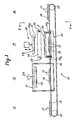
- FIGS 1 and 2 schematically show a transfer printing machine 10 constructed in accordance with the invention.
- the articles to be transfer-printed are supposed to be key caps for the keyboards of typewriters or the like.
- the machine 10 comprises an article loading section 11, a heating section 12, a transfer sheet feeding section 13, a printing section 14, a transfer sheet discharging section 15 and an article unloading section 16.
- a plurality, say, 50 to 200 blank key caps 17 to be transfer-printed are set in a frame or holder 18.
- the holder is made of a material which does not substantially expand when heated, or a material which does not absorb infrared radiation or which has a very low thermal expansion coefficient so that during the course of printing the key caps are held in proper registration with the pattern on the transfer sheet to be transferred onto the key caps.
- the material of the holder 18 may be selected from aluminium, copper, other metals plated with chromium, and ceramics.
- the surface of the holder, if it is made of metal, is preferably polished to provide a highly reflective surface.
- An endless belt conveyor 19 extends between the article loading section 11 and the article unloading section 16 with the heating section 12 and the printing section 14 being interposed therebetween.
- the belt 19 is trained about a plurality of rollers, only two of which are shown as at 20.
- One of the rollers 20 is driven by a suitable drive not shown in a predetermined timed sequence so as to bring the holder 18 with the key caps 17 therein to the heating section 12, where the conveyor 19 stops for a predetermined period of time or slows down for heating the key caps to a predetermined temperature. Then the conveyor 19 brings the holder 18 to the printing section 14 and again stops there for transfer printing to be performed on the heated key caps and then carries them to the unloading section 16.
- the heating section 12 comprises a housing 21 through which the conveyor 19 passes and a heating device 22 the height of which above the conveyor 19 is adjustable by means of a handle 23 provided outside the housing 21.
- the heating device 22 produces infrared radiation having a wavelength of about 1.5 um to 1 mm, preferably, 3 pm to 50 pm.
- the temperature to which the blank key caps 17 are heated can be adjusted by changing the time the key caps are heated, that is, the time they are held in the heating section 12, or by changing the temperature of the heater 22, or by changing the height or distance between the heater 22 and the key caps 17 by means of the handle 23.
- the interior wall surface of the housing 21 is preferably made of a material which reflects infrared rays so as to cause the key caps 17 to absorb the heat produced by the heater 22 for efficient use of the heat energy and enable uniform heating of all the key caps.
- the interior wall surface of the housing 21 may be made of the same material as the key cap holder 18.
- the conveyor 19 carries the holder 18 with the heated blank key caps therein to the printing section 14 and stops there for transfer printing to be effected in a manner to be described in detail later.
- the printing section 14 comprises a transfer sheet supporting device 24 including a frame 25 disposed above the conveyor 19 for supporting a transfer sheet S and a pressing device 26 including a pad 27 disposed above the frame 25 so as to be pressed down against the key caps 17.
- the transfer sheet feeding section 13 comprises a transfer sheet carrier 28 and a device 30 for supplying a transfer sheet S to the carrier 28.
- the carrier 28 is supported by a pair of guide rails 29 extending horizontally over the conveyor 19 perpendicularly thereto, so the carrier 28 is movable between a position above the frame 25 of the transfer sheet supporting device 24 and a position above the transfer sheet supplying device 30.
- the carrier 28 picks up a transfer sheet S with its pattern side facing downward from a stack of transfer sheets S on the supplier 30 by means of suction and carries the sheet to the position above the frame 25 and then releases the sheet to be placed on the frame 25, which holds the transfer sheet S with its pattern side down in proper position by means of a suitable device which may, for example, be a mechanical clamper or a suctioning device not shown but incorporated in the frame 25.
- the conveyor 19 stops for a predetermined period of time, so that a suitable positioning device positions the holder 18 and the key caps 17 therein in proper registration with the pattern of the transfer sheet on the frame 25.
- the positioning device may employ either a mechanical stopper or a photoelectric detector.
- the pressing device 26 is operated to lower the pad 27 as far as the mounting plate 26a of the pad 27 pushes the frame 25 of the transfer sheet supporting device 24 downwardly against the resiliency of springs 24a, with the pad 27 pressing the pattern side of the transfer sheet S against the top surfaces of the key caps 17 to be transfer-printed.
- the pad 27 is made of a suitable material such as silicone rubber and formed with a plurality of projections 27a each having a convexly curved under surface generally complementary with the corresponding top surface, if concavely curved, of each key cap 17.
- the pad 27 is provided with as many such projections 27a as there are key caps 17 to be transfer-printed.
- the pad 27 is removable from the mounting plate 26a for replacement by another pad having a different configuration or projections arranged in a different pattern corresponding to the shape, configuration or arrangement of the articles to be transfer-printed.
- thermo-diffusible dye or dyes that form the pattern or image on the transfer sheet are transferred by the heat in the key caps to the surfaces of the key caps so as to accurately reproduce the pattern or image thereon.
- the transfer sheet may comprise a substrate layer and a pattern layer comprising letters, figures and/or other symbols or designs formed on the substrate layer with thermo-diffusible dye.
- the transfer sheet may also comprise a substrate layer, a releasable layer formed on the substrate, a pattern layer formed on the releasable layer and comprising letters, figures and/or other symbols or designs and an adhesive layer formed on the pattern layer.
- thermo-diffusible dye is transferred to the surface of each key cap by the heat stored in the key cap previously heated in the heating section 12, with the dye particles sublimating into the surface of the key cap to reproduce the original image thereon. It is not necessary to heat the transfer sheet or the key caps again in the printing section 14. If the temperature of the heated key caps is below the required level, it is necessary to provide the pad 27 with a heater to apply heat to the transfer sheet when pressed against the surfaces of the key caps.
- the pad 27 is raised, whereupon the frame 25 supporting the transfer sheet S is also raised from on the surfaces of the key caps 17 thereby to prevent the transfer sheet from contacting the key caps again to smear the printed surfaces thereof.
- the carrier 28 for supplying a new transfer sheet may be used in such a manner that the carrier 28 picks up the transfer sheet S from on the frame 25 by suction and carries the sheet to the discharging section 15 provided on the side of the printing section 14 opposite the transfer sheet feeding section 13 and then releases the sheet to drop into a receptacle 15a.
- a separate device 31 for removing the used transfer sheet from on the frame 25 is provided.
- the remover 31 is supported by the previously mentioned guide rails 29 so as to be movable between a position above the frame 25 in the printing section 14 and a position above the receptacle 15a in the discharging section 15.
- the remover 31 picks up the sheet S from on the frame 25 by suction and carries the sheet away to release it into the receptacle 15a.
- Figures 3 through 26 show in more concrete form a machine constructed in accordance with the invention, with the same reference numerals or symbols as in Figures 1 and 2 designating the corresponding parts or members.
- the heating section 12 and the article unloading section 16 are arranged in parallel with each other, with the printing section 14, the transfer sheet feeding section 13 and the transfer sheet discharging section 15 being interposed between the heating section and the article unloading section.
- the article loading section 11 is partially shown at the left side of the heating section 12.
- the heating section 12 Inside the housing 21 of the heating section 12 there are provided three horizontal support plates 12a, 12b and 12c extending in parallel with each other, with a pair of endless conveyor belts 19a and 19b interposed between the support plates 12a and 12b and between the support plates 12b and 12c. At the right end of the heating section 12 there are provided a pair of endless conveyor belts 19c and 19d in an opening 12d formed in the support plate 12b.
- the belts 19c and 19d extend horizontally in the direction perpendicular to the direction of the belts 19a and 19b and are vertically movable by means of a suitable raising and lowering device such as a pneumatic cylinder 12e ( Figure 4) between an upper position where the upper surface of the belts 19c and 19d are raised slightly above the upper surface of the belts 19a and 19b and a lower position where the belts 19c and 19d are lowered below the upper surface of the belts 19a and 19b.
- a stopper 12f is provided on the support plate 12b at the right side of the belt 19d.
- the key cap holder 18 with blank key caps 17 therein is introduced into the housing 21 through an inlet opening 21a formed in the front end wall 21 b thereof (as shown in Figure 4) and carried by the belts 19a and 19b through the housing 21 and stopped by the stopper 12f ( Figure 3), whereupon the belts 19c and 19d are raised to the upper position and carry the key cap holder 18 laterally to the printing section 14 through an outlet opening 21c ( Figure 4) in the side wall of the housing.
- the infrared radiation heater 22 provided on the ceiling of the housing 21 heats the key caps 17 in the holder 18 as they are carried through the housing 21.
- An inlet shutter 21d and an outlet shutter 21e are preferably provided on the inlet openings 21 a and the outlet opening 21c, respectively ( Figure 4).
- horizontal support plate 14a is secured to a machine frame or housing 14b at much the same height or level as the level of the support plates 12a, 12b and 12c in the heating section 12.
- the support plate 14a is formed with a pair of parallel slots 14c and 14d which extend in general alignment with the conveyor belts 19c and 19d in the heating section 12.
- a pair of endless conveyor chains 19e and 19f are trained about two pairs of sprocket wheels 40a, 40b and 40c, 40d so that the upper horizontal portions 19e' and 19f' of the chains 19e and 19f are disposed in the slots 14c and 14d, respectively ( Figures 12 to 14).
- the chains 19e and 19f and the sprocket wheels 40a to 40d are shown like belts and rollers for simplicity of illustration. Belts and rollers may also be used instead of the chains and sprocket wheels.
- Each of the upper horizontal chain portions 19e' and 19f' is supported by a horizontal tensioning plate 41 ( Figures 19 and 20) which can be vertically moved by a pair of pneumatic cylinders 42 fixed to the machine frame so that the chain portions 19e' and 19f' are vertically movable between an upper and a lower position.
- the upper chain portions 19e' and 19f' are slightly above the upper surface of the horizontal support plate 14a as shown in Figure 20 and are tensioned so that the chains 19e and 19f can be moved in the manner to be described presently.
- the upper chain portions 19e' and 19f' are slackened to a level slightly below the horizontal support plate 14a as shown in Figure 19.
- the sprocket wheels 40a and 40b are fixed to a shaft 43 journaled at its opposite ends in bearings 44 secured to the machine frame at one side of the support plate 14a and the sprocket wheels 40c and 40d are fixed to a shaft 45 parallel with the shaft 43 and journaled at its opposite ends in bearings 46 secured to the machine frame at the opposite side of the support plate 14a.
- the shaft 45 is driven by a motor 47 shown in Figure 14 through a belt-and-pulley connection 48.
- a pair of parallel guide rails 49a and 49b are provided on the support plate 14a laterally outside the slots 14c and 14b, respectively ( Figures 12 to 14).
- Each guide rail is divided into two longitudinal half sections, which are longitudinally separated by an intermediate space 50a, 50b for the purpose to be described later.
- a forward stopper 51 is provided in an opening 52 formed in the support plate 14a adjacent the forward end thereof in the running direction of the chains 19e and 19f.
- the stopper 51 is vertically movable by a pneumatic cylinder 51a a between an upper position where it projects above the level of the upper chain portions 19e' and 19f' as raised or tensioned and a lower position where it is below the level of the horizontal support plate 14a ( Figure 18).
- a side stopper 53 which comprises a stationary rear block 53a fixed to the upper surface of the horizontal plate 14a and a movable front block 53b whose position is adjustable by means of bolts 53c and nuts 53d in the direction perpendicular to the direction of the guide rail 49b ( Figures 13 and 17).
- a side positioner 54 Opposite the side stopper 53 and in the intermediate space 50a in the other guide rail 49a there is provided a side positioner 54 which, as shown in Figures 15 and 16, comprises a push head 54a, an L-shaped arm 54b pivoted to the machine frame at 54c and a pneumatic cylinder 54d for driving the head 54a.
- a side positioner 54 which, as shown in Figures 15 and 16, comprises a push head 54a, an L-shaped arm 54b pivoted to the machine frame at 54c and a pneumatic cylinder 54d for driving the head 54a.
- a rear positioner 55 is provided in an opening 56 formed in the support plate 14a adjacent the end thereof opposite the forward stopper 51.
- the rear positioner 55 is of substantially the same construction as the side positioner 54 and comprises a push head 55a similar to the push head 54a of the side positioner 54, an L-shaped arm and a pneumatic cylinder, the latter two of which are not shown.
- the head 55a When the head 55a is tilted, it lowers below the level of the horizontal support plate 14a and when the head 55a is quickly driven to the upright position, it pushes the key cap holder 18 against the forward stopper 51.
- the holder 18 rides on and is carried by the conveyor chains 19e and 19f of the printing section 14 running in the direction indicated by an arrow X, with the rails 49a and 49b guiding the holder 18 as far as the forward end of the holder 18 is stopped by the forward stopper 51 projecting above the level of the conveyor chains 19e and 19f at that time.
- the side and rear positioners 54 and 55 are operated to cause the push heads 54a and 55a to strike the key cap holder 18 at the lateral and rear sides thereof, respectively, and push the holder 18 against the forward and side stoppers 51 and 53 thereby to put the holder 18 into proper registration with the transfer sheet on the frame 25 just above the holder 18.
- the frame 25 is rectangular in shape and has four depending legs 57 each passing downwardly through the horizontal support plate 14a so as to be supported by a spring device 58 ( Figures 5 and 14) so that the frame 25 on top of the legs 57 can be resiliently pushed downwardly as will be described presently.
- the frame 25 includes a passage or conduit 25a ( Figure 14) to which suction is applied by a vacuum generator 80 through pipes 59.
- the frame 25 is formed in the upper wall thereof with a plurality of small holes 25b communicating with the suction conduit 25a in the frame, so that suction is applied through the holes 25b to the four edges of a transfer sheet S placed on the frame 25 in the manner to be described presently.
- the transfer sheet carrier 28 is movable along the guide rods 29 between a first position just above a transfer sheet supplier 30 and a second position just above the above-mentioned frame 25 in the printing section ( Figures 5 to 8).
- a suitable drive not shown but enclosed in the casing of the carrier 28 drives the carrier 28 until it is stopped by a pair of stoppers 61 above the first position or another pair of stoppers 62 above the second position.
- the carrier 28 is provided with a plurality of depending suction pads 28a to which suction is supplied from the vacuum source 80 through a pipe 28b.
- a transfer sheet supplier 30 supports a stack of transfer sheets S, and is raised by a suitable device 30a such as an air cylinder ( Figure 5), so that the suction pads 28a pick up the uppermost transfer sheet S from the stack.
- the carrier 28 carries the transfer sheet to the position above the frame 25 of the printing section 14, where the carrier 28 releases the transfer sheet, which the frame 25 receives and holds by means of suction applied to the sheet through the holes 25b formed in the upper surface of the frame 25.
- the carrier 28 then returns to the original position above the supplier 30 and picks up the next transfer sheet from the stack on the supplier.
- each cylinder has a piston rod 63a secured to the upperside of a mounting member 26a, to the underside of which a transfer pad 27 is attached removably.
- a rectangular holding frame 26b depends from the mounting member 26a by means of four rods, only two of which is shown at 26c, so as to be disposed about and normally slightly below the transfer pad 27 ( Figure 24). With each of the rods 26c being connected to suitable resilient means 26d, the holding frame 26b is resiliently yieldable upwardly.
- the mounting member 26a is also provided at the four corners of its underside with four depending rods 26e each having its lower end 26f normally disposed slightly below the holding frame 26b ( Figure 24).
- the rods 26e are provided with a compression coil spring 26g and are resiliently yieldable upwardly.
- the support members 14e are of such a height above the plate 14a as to keep the under surface of the frame 25 out of contact with the guide rails 49a, 49b, the stoppers 51, 53 and the push heads 54a, 55a while assuring pressing contact of the transfer sheet on the frame 25 with the top surfaces of the key caps in the holder 18.
- the pressing device 26 is raised so that the frame 26b and the legs 26e are restored to their original lower position while the frame 25 is restored to their original raised position thereby to separate the used transfer sheet from on the key caps 17 onto which the images on the transfer sheet have been transferred.
- the key cap holder 18 with the printed key caps therein is then conveyed from the printing section 14 to the article unloading section 16 by lowering the forward stopper 51 and raising the conveyor chains 19e and 19f into driving contact with the bottom surface of the key cap holder 18.
- the unloading section 16 there is provided a conveyor system similar to that provided in the heating section 12, and the same reference numerals or symbols with a prime designate corresponding members.
- the conveyor belts 19c' and 19d' at their raised position receive the key cap holder 18 being conveyed from the printing section 14 and convey the holder as far as the holder is stopped by a stopper 64 ( Figure 3), whereupon the belts 19c' and 19d' are lowered to place the holder 18 on the conveyor belts 19a' and 19b', which carry the holder leftward in Figure 3.
- the transfer sheet discharging section 15 is provided at the side of the printing section 14 opposite the transfer sheet feeding section 13.
- the remover 31 is provided with a suction device 31 a and a pneumatic cylinder 31 b for projecting and retracting the suction device.
- the suction device 31a a When projected, the suction device 31a a is positioned slightly above one edge of the used transfer sheet S still held on the frame 25, so that with the frame 25 having been disconnected from the source of vacuum 80, the suction device 31a picks up the transfer sheet from on the frame 25.
- the suction device 31a a carries the transfer sheet away and releases it into the receptacle 15a, thereby completing one cycle of operation of transfer printing.
- the above operation is conducted on one key cap holder after another supplied from the loading section 11, with a controller 65 controlling the electromagnetic valves 66a through 66q and the motor 47 in timed sequence in accordance with a predetermined program.
- a compressor 90 supplies compressed air to the cylinders provided in the machine.
- Figures 27, 28 and 29 show a key cap holder 18 particularly suitable for use in the transfer printing machine of the invention.
- the holder is made of a material which does not substantially expand when heated.
- the holder is formed in the upper surface thereof with a plurality of recesses 18a of the same or different shapes and sizes in accordance with the shapes and sizes of the key caps 17 to be put in the recesses.
- a central cylindrical hole 18b is preferably formed in the bottom of each recess 18a to reduce the amount of the metal and consequently the weight of the holder.
- Figures 30 and 31 show a transfer sheet S particularly suitable for use in the machine of the invention.
- the transfer sheet comprises a substrate 70a of paper 50 pm to 60 pm thick backed with a foil 70b of aluminium 5 um to 6 pm thick, and a pattern layer 70c formed on the upper surface of the substrate 70a with a mixture of thermo-diffusible dye or dyes and a binder. Microscopically, some of the mixture has penetrated into the surface of the substrate 70a.
- the transfer sheet has as many small square and/or rectangular areas or sections 70d as there are key caps to be transfer-printed, each section 70d corresponding to one of the key caps and having a pattern layer comprising a symbol or design to be transferred onto the corresponding key cap and being defined at four sides by a slit or cut 70e.
- the provision of slits or cuts 70e to define each of the sections 70d on the transfer sheet helps the projections 27a on the pressure pad 27 when pressed onto the transfer sheet to press the corresponding sections 70d into closer contact with the top surfaces of the key caps thereby to enable accurate transfer printing of the pattern or image onto the key caps.
- the pattern layer on the section 70d may also comprise a square or rectangular shape covering the whole surface area of the section and consequently the whole top surface of the key cap.
Landscapes
- Engineering & Computer Science (AREA)
- Mechanical Engineering (AREA)
- Printing Methods (AREA)
Description
- This invention generally relates to transfer printing and more particularly to a machine for transfer printing figures, letters, other symbols or designs on plastic articles such as molded plastic key caps for business-machine and other typewriter-like keyboards.
- There is disclosed in Japanese Patent Application No. 57-145291 (JP-A-59-35976) a method of transfer printing figures, letters and/or other symbols accurately and precisely at required positions on the surfaces of molded plastic articles by a simple process and in such a manner that the transfer-printed image on the plastic surface remains highly resistive to abrasion and/ or scratching. This method employs a transfer sheet which comprises a substrate and a pattern layer formed thereon with thermo-diffusible colorants. The pattern comprises one or more figures, letters, other symbols or designs or a combination thereof, which will be referred to as a pattern or image when necessary for simplicity of description.
- According to this method, molded plastic articles each having a surface to be transfer-printed are arranged in an array and heated to a predetermined temperature, and a transfer sheet is placed over the array, with the pattern layer of the transfer sheet being in contact with the surfaces of the articles to be transfer-printed. Then a pad having a plurality of projections made of elastic material and each having a curved outer surface is pressed against the transfer sheet so as to bring the pattern layer thereon into closer contact with the surfaces of the articles so that the images on the transfer sheet are transferred onto the surfaces of the articles, whereupon the pad and then the transfer sheet are removed from on the articles.
- The above method has proved to be particularly useful in transfer printing on articles such as molded plastic key caps for the keyboards of typewriters or other business machines, which requires accurate positioning of the transfer sheet relative to the articles for transfer printing.
- For carrying out the above-mentioned method, however, it has been impossible to use various known printing machines as they are chiefly for the following reasons. In the above-mentioned transfer printing method, the articles to be transfer-printed must be heated before a transfer sheet is placed on the surfaces of the articles to be transfer-printed. With the conventional machine, when the articles to be transfer-printed are heated, the frame or holder in which the articles are set or supported is also heated at the same time and thermally expands so that the articles held therein are displaced from the originally set positions and it becomes impossible to bring the pattern on the transfer sheet into accurate registration with the surfaces of the articles to be transfer-printed.
- Accordingly, the primary object of the invention is to provide a transfer printing machine which is capable of conducting transfer printing accurately and efficiently.
- Another object of the invention is to provide such a transfer printing machine as aforesaid which is capable of transfer printing figures, letters and/or other symbols or designs on a plurality of articles, particularly molded plastic objects such as key caps for typewriters or the like business machines simultaneously in a single shot without intolerable displacement of the printed images from their proper position on the articles.
- To attain the above objects, the invention provides the apparatus according to
claim 1. - Briefly stated, in accordance with the invention there is provided a transfer printing machine in which the articles to be transfer printed such as molded plastic key caps for the keyboards of typewriters or like business machines are held in a holder made of a material which does not substantially expand when heated. The articles are heated by an infrared radiation heater to a predetermined temperature. The holder with the heated articles therein is then held at a predetermined position, and a transfer sheet having letters, figures and/or other symbols or designs formed thereon with thermo-diffusible dye is held above the heated articles with each of the images on the transfer sheet in proper registration with the surface of the corresponding one of the articles, and then a pressing pad is pressed against the transfer sheet so that the diffusion dye constituting the images on the transfer sheet sublimates into the surface of the articles to reproduce the images on the surface of the articles. The used transfer sheet is then removed from on the articles and discarded.
- The invention will be described in detail with reference to the accompanying drawings.
-
- Figure 1 schematically shows a transfer printing machine in one embodiment of the invention;
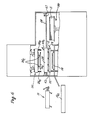
- Figure 2 is a view taken along line II-II in Figure 1;
- Figure 3 is a top plan view, partially cut away, of a transfer printing machine in another embodiment of the invention;
- Figure 4 is a slightly enlarged front view, partially cut away, of the machine as viewed from the right side in Figure 3;
- Figure 5 is a side view of the printing section, the transfer sheet feeding section and the transfer sheet discharging section of the machine shown in Figures 3 and 4, with some of the component parts being not shown for simplicity of illustration;
- Figures 6, 7 and 8 are views similar to Figure 5 but showing the component parts in different operative positions;
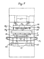
- Figure 9 is a front view of the printing section of the machine shown in Figures 3 to 8, with some of the component parts being not shown for simplicity of illustration;
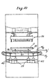
- Figures 10 and 11 are views similar to Figure 9 but showing the component parts in different operative positions;
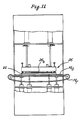
- Figure 12 is an enlarged plan view taken along line XII-XII in Figure 5, with the frame for holding the transfer sheet being not shown for simplicity of illustration;
- Figure 13 is an enlarged view of the printing section shown in Figure 12;
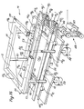
- Figure 14 is a perspective view as viewed in the direction of the arrow Y in Figures 12 and 13;
- Figures 15, 16, 17, 18, 19, 20, 21 and 22 are enlarged views taken along lines A-A, B-B, C-C, D-D, E-E and F-F, in Figure 13;
- Figure 23 is an enlarged view taken along line G-G in Figure 5;
- Figures 24, 25 and 26 are side views showing successive steps of operation of the pressing device in cooperation with the frame for holding a transfer sheet;
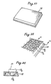
- Figure 27 is a somewhat schematic perspective view of a key cap holder used in the machine of the invention;
- Figure 28 is an enlarged view of a part of the key cap holder;
- Figure 29 is a sectional view taken along line H-H in Figure 28;
- Figure 30 is a perspective view of a part of the transfer sheet used with the machine of the invention;
- Figure 31 is a schematic, microscopically enlarged sectional view of the transfer sheet shown in Figure 30; and
- Figure 32 diagrammatically shows a circuit for controlling the cylinders and suction devices in the machine of the invention.
- Figures 1 and 2 schematically show a
transfer printing machine 10 constructed in accordance with the invention. In the following description the articles to be transfer-printed are supposed to be key caps for the keyboards of typewriters or the like. - The
machine 10 comprises anarticle loading section 11, aheating section 12, a transfersheet feeding section 13, aprinting section 14, a transfersheet discharging section 15 and anarticle unloading section 16. - A plurality, say, 50 to 200
blank key caps 17 to be transfer-printed are set in a frame or holder 18. The holder is made of a material which does not substantially expand when heated, or a material which does not absorb infrared radiation or which has a very low thermal expansion coefficient so that during the course of printing the key caps are held in proper registration with the pattern on the transfer sheet to be transferred onto the key caps. - The material of the
holder 18 may be selected from aluminium, copper, other metals plated with chromium, and ceramics. The surface of the holder, if it is made of metal, is preferably polished to provide a highly reflective surface. - An
endless belt conveyor 19 extends between thearticle loading section 11 and thearticle unloading section 16 with theheating section 12 and theprinting section 14 being interposed therebetween. Thebelt 19 is trained about a plurality of rollers, only two of which are shown as at 20. One of therollers 20 is driven by a suitable drive not shown in a predetermined timed sequence so as to bring theholder 18 with thekey caps 17 therein to theheating section 12, where theconveyor 19 stops for a predetermined period of time or slows down for heating the key caps to a predetermined temperature. Then theconveyor 19 brings theholder 18 to theprinting section 14 and again stops there for transfer printing to be performed on the heated key caps and then carries them to theunloading section 16. - The
heating section 12 comprises ahousing 21 through which theconveyor 19 passes and aheating device 22 the height of which above theconveyor 19 is adjustable by means of ahandle 23 provided outside thehousing 21. Theheating device 22 produces infrared radiation having a wavelength of about 1.5 um to 1 mm, preferably, 3 pm to 50 pm. - The temperature to which the
blank key caps 17 are heated can be adjusted by changing the time the key caps are heated, that is, the time they are held in theheating section 12, or by changing the temperature of theheater 22, or by changing the height or distance between theheater 22 and thekey caps 17 by means of thehandle 23. - The interior wall surface of the
housing 21 is preferably made of a material which reflects infrared rays so as to cause thekey caps 17 to absorb the heat produced by theheater 22 for efficient use of the heat energy and enable uniform heating of all the key caps. The interior wall surface of thehousing 21 may be made of the same material as thekey cap holder 18. - After the heating step, the
conveyor 19 carries theholder 18 with the heated blank key caps therein to theprinting section 14 and stops there for transfer printing to be effected in a manner to be described in detail later. Theprinting section 14 comprises a transfersheet supporting device 24 including aframe 25 disposed above theconveyor 19 for supporting a transfer sheet S and apressing device 26 including apad 27 disposed above theframe 25 so as to be pressed down against thekey caps 17. - As shown in Figure 2, the transfer
sheet feeding section 13 comprises atransfer sheet carrier 28 and adevice 30 for supplying a transfer sheet S to thecarrier 28. Thecarrier 28 is supported by a pair ofguide rails 29 extending horizontally over theconveyor 19 perpendicularly thereto, so thecarrier 28 is movable between a position above theframe 25 of the transfersheet supporting device 24 and a position above the transfersheet supplying device 30. Thecarrier 28 picks up a transfer sheet S with its pattern side facing downward from a stack of transfer sheets S on thesupplier 30 by means of suction and carries the sheet to the position above theframe 25 and then releases the sheet to be placed on theframe 25, which holds the transfer sheet S with its pattern side down in proper position by means of a suitable device which may, for example, be a mechanical clamper or a suctioning device not shown but incorporated in theframe 25. - When the
key cap holder 18 carried by theconveyor 19 reaches theprinting section 14, theconveyor 19 stops for a predetermined period of time, so that a suitable positioning device positions theholder 18 and thekey caps 17 therein in proper registration with the pattern of the transfer sheet on theframe 25. The positioning device may employ either a mechanical stopper or a photoelectric detector. - When the transfer sheet S and the
holder 18 with thekey caps 17 therein are positioned in proper registration with each other, thepressing device 26 is operated to lower thepad 27 as far as themounting plate 26a of thepad 27 pushes theframe 25 of the transfersheet supporting device 24 downwardly against the resiliency ofsprings 24a, with thepad 27 pressing the pattern side of the transfer sheet S against the top surfaces of thekey caps 17 to be transfer-printed. Thepad 27 is made of a suitable material such as silicone rubber and formed with a plurality ofprojections 27a each having a convexly curved under surface generally complementary with the corresponding top surface, if concavely curved, of eachkey cap 17. Thepad 27 is provided with as manysuch projections 27a as there arekey caps 17 to be transfer-printed. Thepad 27 is removable from the mountingplate 26a for replacement by another pad having a different configuration or projections arranged in a different pattern corresponding to the shape, configuration or arrangement of the articles to be transfer-printed. - As the image side of the transfer sheet is pressed against the surfaces of the blank key caps which have been heated to a required temperature, the thermo-diffusible dye or dyes that form the pattern or image on the transfer sheet are transferred by the heat in the key caps to the surfaces of the key caps so as to accurately reproduce the pattern or image thereon.
- The transfer sheet may comprise a substrate layer and a pattern layer comprising letters, figures and/or other symbols or designs formed on the substrate layer with thermo-diffusible dye. The transfer sheet may also comprise a substrate layer, a releasable layer formed on the substrate, a pattern layer formed on the releasable layer and comprising letters, figures and/or other symbols or designs and an adhesive layer formed on the pattern layer.
- When the former type of transfer sheet is used, the thermo-diffusible dye is transferred to the surface of each key cap by the heat stored in the key cap previously heated in the
heating section 12, with the dye particles sublimating into the surface of the key cap to reproduce the original image thereon. It is not necessary to heat the transfer sheet or the key caps again in theprinting section 14. If the temperature of the heated key caps is below the required level, it is necessary to provide thepad 27 with a heater to apply heat to the transfer sheet when pressed against the surfaces of the key caps. - When the sublimation transfer of the dye has been completed, the
pad 27 is raised, whereupon theframe 25 supporting the transfer sheet S is also raised from on the surfaces of thekey caps 17 thereby to prevent the transfer sheet from contacting the key caps again to smear the printed surfaces thereof. - To remove the used transfer sheet from on the
frame 25, thecarrier 28 for supplying a new transfer sheet may be used in such a manner that thecarrier 28 picks up the transfer sheet S from on theframe 25 by suction and carries the sheet to the dischargingsection 15 provided on the side of theprinting section 14 opposite the transfersheet feeding section 13 and then releases the sheet to drop into areceptacle 15a. - In order to improve the working efficiency of the machine, a
separate device 31 for removing the used transfer sheet from on theframe 25 is provided. Theremover 31 is supported by the previously mentionedguide rails 29 so as to be movable between a position above theframe 25 in theprinting section 14 and a position above thereceptacle 15a in the dischargingsection 15. Theremover 31 picks up the sheet S from on theframe 25 by suction and carries the sheet away to release it into thereceptacle 15a. - Figures 3 through 26 show in more concrete form a machine constructed in accordance with the invention, with the same reference numerals or symbols as in Figures 1 and 2 designating the corresponding parts or members.
- As shown in Figure 3, the
heating section 12 and thearticle unloading section 16 are arranged in parallel with each other, with theprinting section 14, the transfersheet feeding section 13 and the transfersheet discharging section 15 being interposed between the heating section and the article unloading section. Thearticle loading section 11 is partially shown at the left side of theheating section 12. - Inside the
housing 21 of theheating section 12 there are provided three horizontal support plates 12a, 12b and 12c extending in parallel with each other, with a pair ofendless conveyor belts 19a and 19b interposed between the support plates 12a and 12b and between the support plates 12b and 12c. At the right end of theheating section 12 there are provided a pair ofendless conveyor belts belts belts 19a and 19b and are vertically movable by means of a suitable raising and lowering device such as a pneumatic cylinder 12e (Figure 4) between an upper position where the upper surface of thebelts belts 19a and 19b and a lower position where thebelts belts 19a and 19b. Astopper 12f is provided on the support plate 12b at the right side of thebelt 19d. - The
key cap holder 18 with blankkey caps 17 therein is introduced into thehousing 21 through aninlet opening 21a formed in the front end wall 21 b thereof (as shown in Figure 4) and carried by thebelts 19a and 19b through thehousing 21 and stopped by thestopper 12f (Figure 3), whereupon thebelts key cap holder 18 laterally to theprinting section 14 through an outlet opening 21c (Figure 4) in the side wall of the housing. Theinfrared radiation heater 22 provided on the ceiling of thehousing 21 heats thekey caps 17 in theholder 18 as they are carried through thehousing 21. Aninlet shutter 21d and anoutlet shutter 21e are preferably provided on theinlet openings 21 a and the outlet opening 21c, respectively (Figure 4). - In the
printing section 14 ahorizontal support plate 14a is secured to a machine frame or housing 14b at much the same height or level as the level of the support plates 12a, 12b and 12c in theheating section 12. - The
support plate 14a is formed with a pair ofparallel slots conveyor belts heating section 12. A pair ofendless conveyor chains sprocket wheels 40a, 40b and 40c, 40d so that the upperhorizontal portions 19e' and 19f' of thechains slots chains - Each of the upper
horizontal chain portions 19e' and 19f' is supported by a horizontal tensioning plate 41 (Figures 19 and 20) which can be vertically moved by a pair ofpneumatic cylinders 42 fixed to the machine frame so that thechain portions 19e' and 19f' are vertically movable between an upper and a lower position. In the upper position theupper chain portions 19e' and 19f' are slightly above the upper surface of thehorizontal support plate 14a as shown in Figure 20 and are tensioned so that thechains upper chain portions 19e' and 19f' are slackened to a level slightly below thehorizontal support plate 14a as shown in Figure 19. - The sprocket wheels 40a and 40b are fixed to a
shaft 43 journaled at its opposite ends inbearings 44 secured to the machine frame at one side of thesupport plate 14a and thesprocket wheels 40c and 40d are fixed to ashaft 45 parallel with theshaft 43 and journaled at its opposite ends inbearings 46 secured to the machine frame at the opposite side of thesupport plate 14a. Theshaft 45 is driven by amotor 47 shown in Figure 14 through a belt-and-pulley connection 48. - A pair of
parallel guide rails 49a and 49b are provided on thesupport plate 14a laterally outside theslots 14c and 14b, respectively (Figures 12 to 14). Each guide rail is divided into two longitudinal half sections, which are longitudinally separated by anintermediate space 50a, 50b for the purpose to be described later. - A
forward stopper 51 is provided in anopening 52 formed in thesupport plate 14a adjacent the forward end thereof in the running direction of thechains stopper 51 is vertically movable by apneumatic cylinder 51a a between an upper position where it projects above the level of theupper chain portions 19e' and 19f' as raised or tensioned and a lower position where it is below the level of thehorizontal support plate 14a (Figure 18). - In the intermediate space 50b in the guide rail 49b there is provided a
side stopper 53 which comprises a stationaryrear block 53a fixed to the upper surface of thehorizontal plate 14a and a movable front block 53b whose position is adjustable by means of bolts 53c and nuts 53d in the direction perpendicular to the direction of the guide rail 49b (Figures 13 and 17). - Opposite the
side stopper 53 and in theintermediate space 50a in theother guide rail 49a there is provided aside positioner 54 which, as shown in Figures 15 and 16, comprises a push head 54a, an L-shaped arm 54b pivoted to the machine frame at 54c and apneumatic cylinder 54d for driving the head 54a. As can be easily seen, when the piston rod of thecylinder 54d is retracted, the head 54a is tilted and lowered, and when the piston rod projects quickly, the head is moved to the upright position thereby to push thekey cap holder 18 against theopposite side stopper 53 as will be described presently. - A
rear positioner 55 is provided in anopening 56 formed in thesupport plate 14a adjacent the end thereof opposite theforward stopper 51. Therear positioner 55 is of substantially the same construction as theside positioner 54 and comprises apush head 55a similar to the push head 54a of theside positioner 54, an L-shaped arm and a pneumatic cylinder, the latter two of which are not shown. When thehead 55a is tilted, it lowers below the level of thehorizontal support plate 14a and when thehead 55a is quickly driven to the upright position, it pushes thekey cap holder 18 against theforward stopper 51. - As the
key cap holder 18 is conveyed by thebelts housing 21 of theheating section 12, theholder 18 rides on and is carried by theconveyor chains printing section 14 running in the direction indicated by an arrow X, with therails 49a and 49b guiding theholder 18 as far as the forward end of theholder 18 is stopped by theforward stopper 51 projecting above the level of theconveyor chains rear positioners key cap holder 18 at the lateral and rear sides thereof, respectively, and push theholder 18 against the forward andside stoppers holder 18 into proper registration with the transfer sheet on theframe 25 just above theholder 18. - The
frame 25 is rectangular in shape and has four dependinglegs 57 each passing downwardly through thehorizontal support plate 14a so as to be supported by a spring device 58 (Figures 5 and 14) so that theframe 25 on top of thelegs 57 can be resiliently pushed downwardly as will be described presently. - The
frame 25 includes a passage orconduit 25a (Figure 14) to which suction is applied by avacuum generator 80 throughpipes 59. Theframe 25 is formed in the upper wall thereof with a plurality of small holes 25b communicating with thesuction conduit 25a in the frame, so that suction is applied through the holes 25b to the four edges of a transfer sheet S placed on theframe 25 in the manner to be described presently. - Above the
horizontal plate 14a there are provided a pair ofparallel guide rods 29 extending over and across theconveyor chains plate 14a to the transfersheet feeding section 13. Thetransfer sheet carrier 28 is movable along theguide rods 29 between a first position just above atransfer sheet supplier 30 and a second position just above the above-mentionedframe 25 in the printing section (Figures 5 to 8). A suitable drive not shown but enclosed in the casing of thecarrier 28 drives thecarrier 28 until it is stopped by a pair ofstoppers 61 above the first position or another pair ofstoppers 62 above the second position. Thecarrier 28 is provided with a plurality of depending suction pads 28a to which suction is supplied from thevacuum source 80 through apipe 28b. - A
transfer sheet supplier 30 supports a stack of transfer sheets S, and is raised by a suitable device 30a such as an air cylinder (Figure 5), so that the suction pads 28a pick up the uppermost transfer sheet S from the stack. Thecarrier 28 carries the transfer sheet to the position above theframe 25 of theprinting section 14, where thecarrier 28 releases the transfer sheet, which theframe 25 receives and holds by means of suction applied to the sheet through the holes 25b formed in the upper surface of theframe 25. Thecarrier 28 then returns to the original position above thesupplier 30 and picks up the next transfer sheet from the stack on the supplier. - Above the transfer
sheet supporting frame 25 thepressing device 26 is supported by twopneumatic cylinders 63 mounted on the machine frame (Figure 5). Each cylinder has apiston rod 63a secured to the upperside of a mountingmember 26a, to the underside of which atransfer pad 27 is attached removably. A rectangular holding frame 26b depends from the mountingmember 26a by means of four rods, only two of which is shown at 26c, so as to be disposed about and normally slightly below the transfer pad 27 (Figure 24). With each of therods 26c being connected to suitableresilient means 26d, the holding frame 26b is resiliently yieldable upwardly. The mountingmember 26a is also provided at the four corners of its underside with four dependingrods 26e each having itslower end 26f normally disposed slightly below the holding frame 26b (Figure 24). Therods 26e are provided with acompression coil spring 26g and are resiliently yieldable upwardly. - When a transfer sheet S is placed on the
frame 25 of the transfersheet supporting device 24 in the previously mentioned manner, thepressing device 26 is lowered until first the lower ends 26f of the fourlegs 26e contact and press the transfer sheet at the four corners thereof onto the frame 25 (Figure 25) and as thelegs 26e are resiliently yielded upwardly, the frame 26b comes into pressing contact with the transfer sheet adjacent the four edges thereof thereby to securely hold the transfer sheet between the twoframes 26b and 25 in proper registration with theprojections 27a of thetransfer pad 27 above and the blankkey caps 17 below (Figure 25). As thepressing device 26 is farther lowered, theframe 25 is pushed downwardly until finally thepad projections 27a contact the upper or reverse surface of the transfer sheet to press the corresponding figures, letters and/or other symbols on the under or obverse surface of the transfer sheet onto the top surfaces of the blank key caps 17to effect transfer printing of the images on the key cap surfaces (Figure 26). Foursupport members 14e are provided on thesupport plate 14a at such positions as to support theframe 25 that has been pushed down in the above-mentioned manner at the four corners thereof. Thesupport members 14e are of such a height above theplate 14a as to keep the under surface of theframe 25 out of contact with theguide rails 49a, 49b, thestoppers frame 25 with the top surfaces of the key caps in theholder 18. There may be provided several sets of support members of different heights for selective use with key caps of different sizes or heights. - When the transfer printing has been completed, the
pressing device 26 is raised so that the frame 26b and thelegs 26e are restored to their original lower position while theframe 25 is restored to their original raised position thereby to separate the used transfer sheet from on thekey caps 17 onto which the images on the transfer sheet have been transferred. - The
key cap holder 18 with the printed key caps therein is then conveyed from theprinting section 14 to thearticle unloading section 16 by lowering theforward stopper 51 and raising theconveyor chains key cap holder 18. - In the
unloading section 16 there is provided a conveyor system similar to that provided in theheating section 12, and the same reference numerals or symbols with a prime designate corresponding members. Theconveyor belts 19c' and 19d' at their raised position receive thekey cap holder 18 being conveyed from theprinting section 14 and convey the holder as far as the holder is stopped by a stopper 64 (Figure 3), whereupon thebelts 19c' and 19d' are lowered to place theholder 18 on theconveyor belts 19a' and 19b', which carry the holder leftward in Figure 3. - The transfer
sheet discharging section 15 is provided at the side of theprinting section 14 opposite the transfersheet feeding section 13. Theremover 31 is provided with a suction device 31 a and a pneumatic cylinder 31 b for projecting and retracting the suction device. When projected, the suction device 31a a is positioned slightly above one edge of the used transfer sheet S still held on theframe 25, so that with theframe 25 having been disconnected from the source ofvacuum 80, the suction device 31a picks up the transfer sheet from on theframe 25. As the piston rod of the cylinder 31b is retracted, the suction device 31a a carries the transfer sheet away and releases it into thereceptacle 15a, thereby completing one cycle of operation of transfer printing. - The above operation is conducted on one key cap holder after another supplied from the
loading section 11, with acontroller 65 controlling the electromagnetic valves 66a through 66q and themotor 47 in timed sequence in accordance with a predetermined program. Acompressor 90 supplies compressed air to the cylinders provided in the machine. - Figures 27, 28 and 29 show a
key cap holder 18 particularly suitable for use in the transfer printing machine of the invention. As previously mentioned, the holder is made of a material which does not substantially expand when heated. - The holder is formed in the upper surface thereof with a plurality of recesses 18a of the same or different shapes and sizes in accordance with the shapes and sizes of the
key caps 17 to be put in the recesses. A central cylindrical hole 18b is preferably formed in the bottom of each recess 18a to reduce the amount of the metal and consequently the weight of the holder. - Figures 30 and 31 show a transfer sheet S particularly suitable for use in the machine of the invention. The transfer sheet comprises a substrate 70a of
paper 50 pm to 60 pm thick backed with a foil 70b of aluminium 5 um to 6 pm thick, and apattern layer 70c formed on the upper surface of the substrate 70a with a mixture of thermo-diffusible dye or dyes and a binder. Microscopically, some of the mixture has penetrated into the surface of the substrate 70a. The transfer sheet has as many small square and/or rectangular areas orsections 70d as there are key caps to be transfer-printed, eachsection 70d corresponding to one of the key caps and having a pattern layer comprising a symbol or design to be transferred onto the corresponding key cap and being defined at four sides by a slit or cut 70e. The provision of slits orcuts 70e to define each of thesections 70d on the transfer sheet helps theprojections 27a on thepressure pad 27 when pressed onto the transfer sheet to press the correspondingsections 70d into closer contact with the top surfaces of the key caps thereby to enable accurate transfer printing of the pattern or image onto the key caps. The pattern layer on thesection 70d may also comprise a square or rectangular shape covering the whole surface area of the section and consequently the whole top surface of the key cap.
Claims (14)
characterized in that said holder (18) is made of a material which does not substantially expand when heated.
Priority Applications (3)
| Application Number | Priority Date | Filing Date | Title |
|---|---|---|---|
| US06/654,127 US4662966A (en) | 1984-09-26 | 1984-09-25 | Apparatus for transfer printing |
| EP84111503A EP0175806B1 (en) | 1984-09-26 | 1984-09-26 | Apparatus for transfer printing |
| DE8484111503T DE3480646D1 (en) | 1984-09-26 | 1984-09-26 | TRANSFER PRINTING DEVICE. |
Applications Claiming Priority (1)
| Application Number | Priority Date | Filing Date | Title |
|---|---|---|---|
| EP84111503A EP0175806B1 (en) | 1984-09-26 | 1984-09-26 | Apparatus for transfer printing |
Publications (2)
| Publication Number | Publication Date |
|---|---|
| EP0175806A1 EP0175806A1 (en) | 1986-04-02 |
| EP0175806B1 true EP0175806B1 (en) | 1989-12-06 |
Family
ID=8192178
Family Applications (1)
| Application Number | Title | Priority Date | Filing Date |
|---|---|---|---|
| EP84111503A Expired EP0175806B1 (en) | 1984-09-26 | 1984-09-26 | Apparatus for transfer printing |
Country Status (3)
| Country | Link |
|---|---|
| US (1) | US4662966A (en) |
| EP (1) | EP0175806B1 (en) |
| DE (1) | DE3480646D1 (en) |
Cited By (2)
| Publication number | Priority date | Publication date | Assignee | Title |
|---|---|---|---|---|
| DE3717639A1 (en) * | 1987-05-26 | 1988-12-15 | Herbert Dipl Ing Wild | Transfer printing press with resilient compensating devices |
| DE19543099A1 (en) * | 1995-11-18 | 1997-05-28 | Huettenhoelscher Maschinenbau | Identity card printing machine |
Families Citing this family (45)
| Publication number | Priority date | Publication date | Assignee | Title |
|---|---|---|---|---|
| JPS61200000A (en) * | 1985-02-28 | 1986-09-04 | 日本写真印刷株式会社 | Manufacture of plastic molded shape, top surface and front side surface thereof have pattern, such as character, symbol, etc., and pattern forming machine |
| GB8614034D0 (en) * | 1986-06-10 | 1986-07-16 | Mascoprint Developments Ltd | Printing |
| CA1335329C (en) * | 1988-09-06 | 1995-04-25 | Donald C. Berghauser | Color sublimation dye transfer from color video prints to ceramic mugs and the like |
| EP1377402A4 (en) * | 2001-03-14 | 2007-12-26 | Key Tech Inc | Method and apparatus for printing a dye image onto a three dimensional object |
| US6465102B1 (en) | 2001-03-22 | 2002-10-15 | General Electric Company | Formed decorative article |
| US6458913B1 (en) | 2001-03-22 | 2002-10-01 | General Electric Company | Insert molded article |
| US6998005B2 (en) * | 2001-03-29 | 2006-02-14 | Fresco Plastics Llc | Method and apparatus for forming dye sublimation images in solid plastic |
| US8308891B2 (en) | 2001-03-29 | 2012-11-13 | Fresco Technologies, Inc. | Method for forming dye sublimation images in solid substrates |
| TWI270478B (en) * | 2001-03-29 | 2007-01-11 | Fresco Plastics | Method and apparatus for continuously forming dye sublimation images in solid substrates |
| DE602004008466T2 (en) * | 2003-06-26 | 2008-05-15 | Key-Tech, Inc. | METHOD FOR THERMALLY PRINTING A PAINTED IMAGE TO A THREE-DIMENSIONAL OBJECT THROUGH THE USE OF FLEXIBLE HEATING ELEMENTS |
| US20100196651A1 (en) * | 2005-09-28 | 2010-08-05 | Sipix Chemical Inc. | Mold manufacturing of an object comprising a functional element, transfering process and object |
| ITBS20050150A1 (en) * | 2005-12-01 | 2007-06-02 | Z R Di Zambetti Romano | SUBLIMATION MACHINE |
| JP5378802B2 (en) * | 2006-02-03 | 2013-12-25 | イナジー・オートモーティブ・システムズ・リサーチ・(ソシエテ・アノニム) | Method and apparatus for manufacturing a fuel tank with internal accessories |
| CA2859554C (en) * | 2006-05-10 | 2016-11-08 | Decoral System Usa Corp. | Apparatuses and methods for decorating objects |
| ITMO20060389A1 (en) * | 2006-11-22 | 2008-05-23 | Viv Int Spa | EQUIPMENT AND METHOD FOR DECORATING OBJECTS |
| US8011922B2 (en) * | 2007-07-30 | 2011-09-06 | Decoral System Usa Corp. | Apparatus for decorating objects by sublimation |
| TWI352016B (en) * | 2008-03-20 | 2011-11-11 | Compal Electronics Inc | Pattern transfer mold and pattern transfer method |
| GB0818109D0 (en) * | 2008-10-03 | 2008-11-05 | Hoggard Peter J | Sublimation printing |
| US8469510B2 (en) * | 2009-01-09 | 2013-06-25 | Oakley, Inc. | Eyewear with enhanced ballistic resistance |
| US8192015B2 (en) | 2009-01-09 | 2012-06-05 | Oakley, Inc. | Eyeglass with enhanced ballistic resistance |
| SG184119A1 (en) * | 2010-03-19 | 2012-10-30 | Oakley Inc | Eyewear |
| US8485094B2 (en) * | 2010-05-05 | 2013-07-16 | Hewlett-Packard Development Company, L.P. | Printer accessory |
| JP5934798B2 (en) | 2011-09-22 | 2016-06-15 | オークリー インコーポレイテッド | Mounting mechanism for eyewear |
| US9122078B2 (en) | 2011-12-01 | 2015-09-01 | Oakley, Inc. | Releasable earstem mounting mechanism for eyewear |
| WO2014036274A2 (en) | 2012-08-31 | 2014-03-06 | Oakley, Inc. | Eyewear having multiple ventilation states |
| GB2522389B (en) | 2012-12-11 | 2019-07-31 | Oakley Inc | Eyewear with outriggers |
| WO2014138159A1 (en) | 2013-03-07 | 2014-09-12 | Oakley, Inc. | Regeneratable ant-fogging element for goggle |
| US10011120B2 (en) | 2013-07-25 | 2018-07-03 | The Hillman Group, Inc. | Single heating platen double-sided sublimation printing process and apparatus |
| US9120326B2 (en) | 2013-07-25 | 2015-09-01 | The Hillman Group, Inc. | Automatic sublimated product customization system and process |
| US9333788B2 (en) | 2013-07-25 | 2016-05-10 | The Hillman Group, Inc. | Integrated sublimation transfer printing apparatus |
| US9403394B2 (en) | 2013-07-25 | 2016-08-02 | The Hillman Group, Inc. | Modular sublimation transfer printing apparatus |
| US9731534B2 (en) | 2013-07-25 | 2017-08-15 | The Hillman Group, Inc. | Automated simultaneous multiple article sublimation printing process and apparatus |
| AU2015235947B2 (en) | 2014-03-27 | 2017-12-07 | Oakley, Inc. | Mounting mechanism for eyewear |
| US9962979B2 (en) | 2015-08-05 | 2018-05-08 | The Hillman Group, Inc. | Semi-automated sublimation printing apparatus |
| WO2017062813A1 (en) | 2015-10-09 | 2017-04-13 | Oakley, Inc. | Headworn supports with passive venting and removable lens |
| CN205130611U (en) * | 2015-11-25 | 2016-04-06 | 美可达电子影像有限公司 | Small -size vacuum belt -Type furnace heat -transfer seal stove |
| US9709817B2 (en) | 2015-12-07 | 2017-07-18 | Oakley, Inc. | Eyewear retention devices and methods |
| EP3387485B1 (en) | 2015-12-08 | 2025-05-07 | Oakley, Inc. | Eyewear traction devices and methods |
| US10359642B2 (en) | 2016-04-22 | 2019-07-23 | Oakley, Inc. | Mounting mechanism for eyewear |
| IT201800007832A1 (en) * | 2018-08-03 | 2020-02-03 | Tecno Decoral Srl | PRESS FOR THE DECORATION OF SLABS BY SUBLIMATION |
| WO2020264538A2 (en) * | 2019-06-28 | 2020-12-30 | Mabbott Robert J | Multi-layer conformal decoration film |
| CN110978810A (en) * | 2019-12-27 | 2020-04-10 | 嵊州向合纺织科技有限公司 | Cloth surface stamp spraying device |
| CN111746101B (en) | 2020-07-29 | 2025-05-02 | 美可达电子影像有限公司 | A rotary outer circular surface thermal transfer production line and automatic thermal transfer method |
| CN111746102A (en) * | 2020-07-31 | 2020-10-09 | 贝塔科技(苏州)有限公司 | A transmission ironing device for garment customization |
| US11186108B1 (en) | 2020-10-16 | 2021-11-30 | Photo U.S.A. Corporation | Sublimation printing on to dark surfaces |
Family Cites Families (9)
| Publication number | Priority date | Publication date | Assignee | Title |
|---|---|---|---|---|
| US3818823A (en) * | 1969-10-27 | 1974-06-25 | Buckbee Mears Co | Heated, vacuum-pressure press |
| US3974014A (en) * | 1974-07-10 | 1976-08-10 | Hallmark Cards, Incorporated | Method for transferring design image to wax articles |
| US3945879A (en) * | 1974-08-30 | 1976-03-23 | Nasa | Apparatus for positioning modular components on a vertical or overhead surface |
| US4033030A (en) * | 1974-09-12 | 1977-07-05 | Mohawk Data Sciences Corporation | Method of manufacturing keyswitch assemblies |
| CH600087A5 (en) * | 1976-02-24 | 1978-06-15 | Schneider & Co W | |
| CH624610A5 (en) * | 1977-02-10 | 1981-08-14 | Cilander Ag | |
| US4174250A (en) * | 1978-04-10 | 1979-11-13 | Freeman Transfer Printing Company, Inc. | Apparatus for sublimation imprinting tiles |
| GB2120169B (en) * | 1982-05-12 | 1985-10-23 | David Durand | Method of applying a dye image to a plastic member and the image bearing member thereby formed |
| US4475458A (en) * | 1983-06-02 | 1984-10-09 | Kennell Joseph F | Vacuum frame for offset printing plates |
-
1984
- 1984-09-25 US US06/654,127 patent/US4662966A/en not_active Expired - Lifetime
- 1984-09-26 DE DE8484111503T patent/DE3480646D1/en not_active Expired - Lifetime
- 1984-09-26 EP EP84111503A patent/EP0175806B1/en not_active Expired
Cited By (3)
| Publication number | Priority date | Publication date | Assignee | Title |
|---|---|---|---|---|
| DE3717639A1 (en) * | 1987-05-26 | 1988-12-15 | Herbert Dipl Ing Wild | Transfer printing press with resilient compensating devices |
| DE19543099A1 (en) * | 1995-11-18 | 1997-05-28 | Huettenhoelscher Maschinenbau | Identity card printing machine |
| DE19543099C2 (en) * | 1995-11-18 | 1998-02-19 | Huettenhoelscher Maschinenbau | Method and device for transferring a print image from a carrier web to a substrate |
Also Published As
| Publication number | Publication date |
|---|---|
| DE3480646D1 (en) | 1990-01-11 |
| US4662966A (en) | 1987-05-05 |
| EP0175806A1 (en) | 1986-04-02 |
Similar Documents
| Publication | Publication Date | Title |
|---|---|---|
| US4662966A (en) | Apparatus for transfer printing | |
| US5553536A (en) | Screen printing apparatus with vacuum conveyor belt | |
| EP0495111B1 (en) | Device and method of transfer printing | |
| US20050179708A1 (en) | Digital printing machine | |
| US6776100B2 (en) | Method and apparatus for transferring an image to a substrate | |
| KR100396861B1 (en) | Laminator for Laminating Film Sheet on Substrate | |
| KR102099466B1 (en) | Automatic system for printing many colors on many sides of molded product by pad | |
| KR20230015931A (en) | Polishing device, processing system and polishing method | |
| US4666294A (en) | Apparatus for exposure of both sides of printed circuit plates | |
| US7954938B2 (en) | Apparatus and process for ink-jet printing | |
| JP6868353B2 (en) | A decoration device for paper leaf blocks and a method for providing individual souvenirs at a customer attraction facility using this device. | |
| KR101990985B1 (en) | Metal sheet printing device and metal sheet printing method | |
| JP2007069954A (en) | Transfer printing device | |
| CN219338925U (en) | Embedded pad pasting ware | |
| JP2023537557A (en) | Hybrid inkjet printer capable of continuous output | |
| KR930002897Y1 (en) | Dakage marking device | |
| JP4303939B2 (en) | Mounting device for cylindrical labels for packaging | |
| WO1991019221A1 (en) | Method and apparatus for producing thermal slide transparencies | |
| KR102926453B1 (en) | Apparatus Capable of Printing and Cutting Box Blanks | |
| JPH08197799A (en) | Paper holding mechanism of image forming device | |
| JPH08316253A (en) | Semiconductor pellet transfer device and semiconductor pellet bonding device using the transfer device | |
| JP3797128B2 (en) | Image transfer mechanism for cards | |
| JPH05309823A (en) | Thermal transfer printing method and thermal transfer printing device | |
| JP2734527B2 (en) | Screen printing machine | |
| JP3862207B2 (en) | Printing device |
Legal Events
| Date | Code | Title | Description |
|---|---|---|---|
| PUAI | Public reference made under article 153(3) epc to a published international application that has entered the european phase |
Free format text: ORIGINAL CODE: 0009012 |
|
| AK | Designated contracting states |
Kind code of ref document: A1 Designated state(s): DE FR GB IT NL |
|
| 17P | Request for examination filed |
Effective date: 19860912 |
|
| 17Q | First examination report despatched |
Effective date: 19880211 |
|
| GRAA | (expected) grant |
Free format text: ORIGINAL CODE: 0009210 |
|
| AK | Designated contracting states |
Kind code of ref document: B1 Designated state(s): DE FR GB IT NL |
|
| REF | Corresponds to: |
Ref document number: 3480646 Country of ref document: DE Date of ref document: 19900111 |
|
| ITF | It: translation for a ep patent filed | ||
| ET | Fr: translation filed | ||
| PLBE | No opposition filed within time limit |
Free format text: ORIGINAL CODE: 0009261 |
|
| STAA | Information on the status of an ep patent application or granted ep patent |
Free format text: STATUS: NO OPPOSITION FILED WITHIN TIME LIMIT |
|
| 26N | No opposition filed | ||
| ITTA | It: last paid annual fee | ||
| PGFP | Annual fee paid to national office [announced via postgrant information from national office to epo] |
Ref country code: FR Payment date: 19950817 Year of fee payment: 12 |
|
| PGFP | Annual fee paid to national office [announced via postgrant information from national office to epo] |
Ref country code: GB Payment date: 19950907 Year of fee payment: 12 |
|
| PGFP | Annual fee paid to national office [announced via postgrant information from national office to epo] |
Ref country code: NL Payment date: 19950922 Year of fee payment: 12 |
|
| PGFP | Annual fee paid to national office [announced via postgrant information from national office to epo] |
Ref country code: DE Payment date: 19951031 Year of fee payment: 12 |
|
| PG25 | Lapsed in a contracting state [announced via postgrant information from national office to epo] |
Ref country code: GB Effective date: 19960926 |
|
| PG25 | Lapsed in a contracting state [announced via postgrant information from national office to epo] |
Ref country code: FR Effective date: 19960930 |
|
| PG25 | Lapsed in a contracting state [announced via postgrant information from national office to epo] |
Ref country code: NL Effective date: 19970401 |
|
| GBPC | Gb: european patent ceased through non-payment of renewal fee |
Effective date: 19960926 |
|
| NLV4 | Nl: lapsed or anulled due to non-payment of the annual fee |
Effective date: 19970401 |
|
| PG25 | Lapsed in a contracting state [announced via postgrant information from national office to epo] |
Ref country code: DE Effective date: 19970603 |
|
| REG | Reference to a national code |
Ref country code: FR Ref legal event code: ST |
|
| REG | Reference to a national code |
Ref country code: FR Ref legal event code: ST |