EP0175453B1 - Modular electrical heater - Google Patents
Modular electrical heater Download PDFInfo
- Publication number
- EP0175453B1 EP0175453B1 EP85305153A EP85305153A EP0175453B1 EP 0175453 B1 EP0175453 B1 EP 0175453B1 EP 85305153 A EP85305153 A EP 85305153A EP 85305153 A EP85305153 A EP 85305153A EP 0175453 B1 EP0175453 B1 EP 0175453B1
- Authority
- EP
- European Patent Office
- Prior art keywords
- conductors
- component
- module
- heater according
- heater
- Prior art date
- Legal status (The legal status is an assumption and is not a legal conclusion. Google has not performed a legal analysis and makes no representation as to the accuracy of the status listed.)
- Expired - Lifetime
Links
Images
Classifications
-
- H—ELECTRICITY
- H05—ELECTRIC TECHNIQUES NOT OTHERWISE PROVIDED FOR
- H05B—ELECTRIC HEATING; ELECTRIC LIGHT SOURCES NOT OTHERWISE PROVIDED FOR; CIRCUIT ARRANGEMENTS FOR ELECTRIC LIGHT SOURCES, IN GENERAL
- H05B3/00—Ohmic-resistance heating
- H05B3/10—Heater elements characterised by the composition or nature of the materials or by the arrangement of the conductor
- H05B3/12—Heater elements characterised by the composition or nature of the materials or by the arrangement of the conductor characterised by the composition or nature of the conductive material
- H05B3/14—Heater elements characterised by the composition or nature of the materials or by the arrangement of the conductor characterised by the composition or nature of the conductive material the material being non-metallic
- H05B3/141—Conductive ceramics, e.g. metal oxides, metal carbides, barium titanate, ferrites, zirconia, vitrous compounds
-
- H—ELECTRICITY
- H05—ELECTRIC TECHNIQUES NOT OTHERWISE PROVIDED FOR
- H05B—ELECTRIC HEATING; ELECTRIC LIGHT SOURCES NOT OTHERWISE PROVIDED FOR; CIRCUIT ARRANGEMENTS FOR ELECTRIC LIGHT SOURCES, IN GENERAL
- H05B3/00—Ohmic-resistance heating
- H05B3/40—Heating elements having the shape of rods or tubes
- H05B3/54—Heating elements having the shape of rods or tubes flexible
- H05B3/56—Heating cables
Definitions
- This invention relates to electrical strip heaters.
- Many elongate electrical heaters e.g. for heating pipes, tanks and other apparatus in the chemical process industry, comprise two (or more) relatively low resistance conductors which are connected to the power source and run the length of the heater, with a plurality of heating elements connected in parallel with each other between the conductors (also referred to in the art as electrodes.)
- the heating elements are in the form of a continuous strip of conductive polymer in which the conductors are embedded.
- the heating elements are one or more resistive metallic heating wires.
- the heating wires are wrapped around the conductors, which are insulated except at spaced- apart points where they are connected to the heating wires.
- the heating wires contact the conductors alternately and make multiple wraps around the conductors between the connection points.
- elongate heaters are preferably self-regulating. This is achieved, in conventional conductive polymer heaters, by using a continuous strip of conductive polymer which exhibits PTC behavior. It has also been proposed to make zone heaters self-regulating by connecting the heating wire(s) to one or both of the conductors through a connecting element composed of a ceramic PTC material.
- US-A-4,072,848 discloses a self-regulating heater comprising a pair of flexible elongate parallel conductors which are connectable to a power supply, and a plurality of rigid heating modules connected in parallel with each other between the conductors and in direct.physical contact with the conductors.
- a self-regulating heater comprising
- An important feature of the present invention is the use of leads, preferably wires, to connect the modules to the elongate conductors; if the modules are in direct physical contact with the conductors the differences in thermal expansion coefficients of the materials, and the lack of flexibility, cause serious problems.
- the leads should of course be flexible by comparison with the substrate.
- the heater is sufficiently flexible to be wrapped several times around a pipe having a diameter of 1.27 cm, without damage to the heater.
- the heating component and the temperature-responsive component may both be provided by a single component which has a positive temperature coefficient of resistance or alternatively, the heating component can have a substantially zero temperature coefficient of resistance and the temperature-responsive component can be a separate component which has a positive temperature coefficient of resistance.
- a material is defined as having a "positive temperature coefficient of resistance" if it increases in resistivity, in the temperature range of operation, sufficiently to render the heater self-regulating; preferably the material has an R 14 value of at least 2.5 or an R, oo value of at least 10, and preferably an R 30 value of at least 6, where R 14 is the ratio of the resistivities at the end and beginning of the 14°C range showing the sharpest increase in resistivity; R loo is the ratio of the resistivities at the end and beginning of the 100°C range showing the sharpest increase in resistivity; and R 30 is the ratio of the resistivities at the end and the beginning of the 30°C range showing the sharpest increase in resistivity.
- a material is defined as a ZTC material if it is not a PTC material in the temperature range of operation.
- a self-limiting heater and which comprises
- the rigid insulating substrate may be composed of any suitable material or materials eg. alumina, porcelainized metal, glass or pressed fibrous material.
- the insulating substrate serves the important function of distributing the heat generated by the heating element. This provides a number of advantages, including lengthening the stability and life of the heating element. At the same time, the insulating substrate aids in safety, since it absorbs and distributes mechanical shock and electrical stresses.
- the substrate preferably has dimensions from 2.54 cm to 12.7 cm length, preferably 0.635 cm to 3.81 cm length, 0.0254 cm to 0.254 cm thickness, preferable 0.0508 cm to 0.1524 cm thickness, and 0.254 cm to 3.048 cm width, preferably 0.508 cm to 2.54 cm width.
- the module can be wider, for example at least 2.54 cm wide e.g. 2.54 cm to 30.48 cm wide, especially, depending on the substrate, 5.08 cm to 15.24 cm wide.
- the resistive heating component may comprise a conductive polymer, a ceramic or other resistive material which is, or can be formulated as, a composition which is deposited e.g. printed onto the substrate. After the resistive material has been deposited onto the substrate, it can be treated (e.g. heated to evaporate a solvent or to cause a physical and/or chemical change) so that it adheres firmly to the substrate.
- Preferred resistive materials include Ru0 2 -based ceramics.
- the temperature-responsive component preferably comprises a material which has a positive temperature coefficient of resistance. ff this component is separate from the heating component, it is preferably also secured to, e.g. deposited on, particularly printed onto, the substrate, on the same side or on the opposite side thereof.
- an important feature of the invention is the use of leads, preferably wires, foils or springy clips, to connect the modules to the elongate conductors.
- the leads should be flexible by comparison with the substrate.
- the leads preferably have an aspect ratio greater than 1.0, where the aspect ratio is defined as and length (1) is construed to be that portion between and not attached to the module or elongate conductor and diameter (d) is construed to be an equivalent diameter for the case of non- round leads.
- the equivalent diameter of a non- round lead is the diameter of a circle having the same area as a cross-section through the lead.
- a useful equation may be employed to provide indication of the flexibility of a modular heater of the invention, namely, K is preferably less than 6, especially less than 4.
- 1/d is the aspect ratio of the leads and
- the heater preferably comprises two to twenty modules per linear foot of the heater.
- the heater advantageously further comprises an insulating jacket which comprises mica tape sandwiched between two layers of glass fibers.
- the heater preferably is adapted to be connected to a constant voltage source.
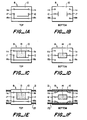
- Figure 1 provides a schematic diagram of the method and apparatus of the invention.
- Figure 1 is divided into sections a-f to show individual steps in making a self-limiting heater of the invention.
- Figures 1A and 1B provide top and bottom views respectively of a heater 8 formed on a substrate 10.
- Figures 1A and 1B show a first, second, third and fourth conductive pads (numerals 11a, 11b, 18a and 18b) secured to the substrate 10.
- the conductive pads 11 a and 11b are common, as are the conductive pads 18a and 18b.
- a conductive pad 17 common to conductive pad 18a (and 18b) and a conductive pad 17 on the bottom of the substrate 10.
- Figure 1c provides a top view of the next step and shows a resistive heating component 13 that has a zero temperature coefficient of resistance which is printed onto the substrate 10 and that makes electrical contact with the conductive pads 11a, 11b and 12.
- Figure 1d provides the next bottom view and shows a temperature-responsive component 14 that has a positive temperature coefficient of resistance which is bonded onto the substrate 10 between conductive pads 12 and 17.
- Figures 1e and 1f show bus bar conductors 21 and 22 which make electrical contact with the conductor pads 11 a, 11 band 18a, 18b, respectively.
- Four Monel pins may be plasma welded to the bus bar conductors 21 and 22 to make electrical contact with the conductor pads 11a, 11 and 18a and 18b.
- the heater 8 is adapted to be connected to a power supply so that current can pass from bus bar conductor 21 through the conductor pads 11a, b; then through the ZTC component 13 and out through conductor pad 12; and through the PTC component 14 and out through conductor pads 17, 18a, b to bus bar conductor 22.
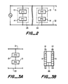
- Figure 2 provides an electrical circuit diagram that corresponds to the heater 8.
- the ZTC component 13 and PTC component 14 are connected in electrical series and the combined resistance of this module 24 is 10 ohms to 100K ohms.
- a plurality of such modules 24 is connected in parallel.
- Figures 3a and 3b provide a circuit diagram and view respectively of a different embodiment of the invention.
- Figure 3a shows a series connection of PTC components 13
- Figure 3b shows the resultant heater, the series connection being provided along an electrical lead 26. It has been found that the series connection of PTC components 13 optimizes the power requirements of the heater.
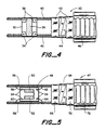
- FIG. 4 illustrates a constant wattage PTC heater 30.
- a resistor pattern 36 was screened on the substrate and connected to the pins #4 by way of a conductive thick film 38. The module resistance was 21K ohms.
- Eight modules were spaced evenly per foot and the Monel pins plasma welded to 14AWG nickel-clad copper stranded wire 40.
- the insulation as shown, was glass (42)/ mica (44)/glass (42) and the insulated cable was sheathed in a stainless steel sheath 46.
- FIG. 5 illustrates a self-regulating PTC heater 47.
- a substrate 48 was provided and nickel cermet gluing PTC chips 50 and 52 to monel pins (54) and the substrate 48.
- the PTC chips 50 and 52 were connected in electrical series.
- Four monel pins were brazed to the substrate; two pins were connected to PTC chips and 14AWG nickel clad copper bus bars 56 using electrical leads 58 and 60, and two pins only to the substrate 48 and bus bars 56 by way of electrical leads 62 and 64.
- the heater 47 was enclosed by a primary braid 66, mica tape 68, a secondary braid 70 and an outside sheath 72.
Abstract
Description
- This invention relates to electrical strip heaters.
- Many elongate electrical heaters, e.g. for heating pipes, tanks and other apparatus in the chemical process industry, comprise two (or more) relatively low resistance conductors which are connected to the power source and run the length of the heater, with a plurality of heating elements connected in parallel with each other between the conductors (also referred to in the art as electrodes.) In conventional conductive polymer strip heaters, the heating elements are in the form of a continuous strip of conductive polymer in which the conductors are embedded. In other conventional heaters, known as zone heaters, the heating elements are one or more resistive metallic heating wires. In zone heaters, the heating wires are wrapped around the conductors, which are insulated except at spaced- apart points where they are connected to the heating wires. The heating wires contact the conductors alternately and make multiple wraps around the conductors between the connection points. For many uses, elongate heaters are preferably self-regulating. This is achieved, in conventional conductive polymer heaters, by using a continuous strip of conductive polymer which exhibits PTC behavior. It has also been proposed to make zone heaters self-regulating by connecting the heating wire(s) to one or both of the conductors through a connecting element composed of a ceramic PTC material.
- Elongate heaters of various kinds, and conductive polymers for use in such heaters, are disclosed in U. S. Patents Nos. 2,952,761, 2,978,665, 3,243,753, 3,351,882, 3,571,777, 3,757,086, 3,793,716, 3,823,217, 3,858,144, 3,861,029, 3,950,604, 4,017,715, 4,072,848, 4,085,286, 4,117,312, 4,177,376, 4,177,446, 4,188,276, 4,237,441, 4,242,573, 4,246,468, 4,250,400, 4,252,692, 4,255,698, 4,271,350, 4,272,471, 4,304,987, 4,309,596, 4,309,597, 4,314,230, 4,314,231, 4,315,237, 4,317,027, 4,318,881, 4,329,551, 4,330,704, 4,334,351, 4,352,083, 4,361,799, 4,388,607, 4,398,084, 4,413,301, 4,425,397, 4,426,339, 4,426,633, 4,427,877, 4,435,639, 4,429,216 and 4,442,139; J. Applied Polymer Science 19, 813-815 (1975), Klason and Kubat; Polymer Engineering and Science 18, 649-653 (1978), Narkis et al; German OLS 2,634,999, 2,746,602, 2,821,799, and European Application Publication Nos. 38,713, 38,714, 38,718, 63,440, 67,679, 68,688, 74,281, 87,884, 92,406, 96,492, 0123540 (Application No. 84 302717.8), 0119807 (Application No. 84301650.2), 0133748 (Application No. 84 304502.2) and 0136039 (corresponding to U.S. Serial No. 524,958).
- US-A-4,072,848 discloses a self-regulating heater comprising a pair of flexible elongate parallel conductors which are connectable to a power supply, and a plurality of rigid heating modules connected in parallel with each other between the conductors and in direct.physical contact with the conductors.
- We have now discovered that substantial improvements and advantages can be provided in the performance and application of elongate self-regulating electrical heaters comprising a pair of flexible elongate parallel conductors which are connectable to a power supply.
- In accordance with the present invention, there is provided a self-regulating heater comprising
- (1) a pair of flexible elongate parallel conductors which are connectable to a power supply; and
- (2) a plurality of rigid heating modules connected in parallel with each other between the conductors, each of said heating modules comprising
- (a) a rigid insulating substrate;
- (b) a resistive heating component which has been deposited on the substrate and which generates heat when the conductors are connected to a suitable power supply; and
- (c) a temperature-responsive component which is thermally coupled to the heating component and which has an electrical property which varies so that, when the heater is connected to the power supply, the heat generated by the module decreased substantially as the temperature of the module approaches an elevated temperature; characterised in that the modules are physically spaced apart from each of the conductors, in that electrical leads physically and electrically connect the modules to the elongate conductors, and in that the portions of each of the leads which are not connected either to a module or to a conductor have a tension and torsion modulus of elasticity less than 6.89 x 10" NT/M2 and an aspect ratio greater than 0.5, where the aspect ratio is defined as length/diameter of the lead and the diameter is an equivalent diameter; wherein the quantity

- I = length of lead;
- d = equivalent diameter of lead;
- E = modulus of elasticity of the elongate parallel conductors;
- D = equivalent diameter of the elongate parallel conductors; and
- F = minimum force required to break the bond between lead to module.
- An important feature of the present invention is the use of leads, preferably wires, to connect the modules to the elongate conductors; if the modules are in direct physical contact with the conductors the differences in thermal expansion coefficients of the materials, and the lack of flexibility, cause serious problems. The leads should of course be flexible by comparison with the substrate. Preferably the heater is sufficiently flexible to be wrapped several times around a pipe having a diameter of 1.27 cm, without damage to the heater.
- The heating component and the temperature-responsive component may both be provided by a single component which has a positive temperature coefficient of resistance or alternatively, the heating component can have a substantially zero temperature coefficient of resistance and the temperature-responsive component can be a separate component which has a positive temperature coefficient of resistance.
- In this specification, a material is defined as having a "positive temperature coefficient of resistance" if it increases in resistivity, in the temperature range of operation, sufficiently to render the heater self-regulating; preferably the material has an R14 value of at least 2.5 or an R,oo value of at least 10, and preferably an R30 value of at least 6, where R14 is the ratio of the resistivities at the end and beginning of the 14°C range showing the sharpest increase in resistivity; Rloo is the ratio of the resistivities at the end and beginning of the 100°C range showing the sharpest increase in resistivity; and R30 is the ratio of the resistivities at the end and the beginning of the 30°C range showing the sharpest increase in resistivity. A material is defined as a ZTC material if it is not a PTC material in the temperature range of operation.
- In one emodiment of the invention there is provided a self-limiting heater and which comprises
- (a) a zero temperature coefficient of resistance heating component which has been deposited on the substrate;
- (b) a separate positive temperature coefficient of resistance component secured to the substrate; and
- (c) a series electrical connection between the zero temperature coefficient of resistance component and the positive temperature coefficient of resistance component.
- The rigid insulating substrate may be composed of any suitable material or materials eg. alumina, porcelainized metal, glass or pressed fibrous material. The insulating substrate serves the important function of distributing the heat generated by the heating element. This provides a number of advantages, including lengthening the stability and life of the heating element. At the same time, the insulating substrate aids in safety, since it absorbs and distributes mechanical shock and electrical stresses. The substrate preferably has dimensions from 2.54 cm to 12.7 cm length, preferably 0.635 cm to 3.81 cm length, 0.0254 cm to 0.254 cm thickness, preferable 0.0508 cm to 0.1524 cm thickness, and 0.254 cm to 3.048 cm width, preferably 0.508 cm to 2.54 cm width. For heating relatively broad substrates, however, the module can be wider, for example at least 2.54 cm wide e.g. 2.54 cm to 30.48 cm wide, especially, depending on the substrate, 5.08 cm to 15.24 cm wide.
- The resistive heating component may comprise a conductive polymer, a ceramic or other resistive material which is, or can be formulated as, a composition which is deposited e.g. printed onto the substrate. After the resistive material has been deposited onto the substrate, it can be treated (e.g. heated to evaporate a solvent or to cause a physical and/or chemical change) so that it adheres firmly to the substrate. Preferred resistive materials include Ru02-based ceramics.
- The temperature-responsive component preferably comprises a material which has a positive temperature coefficient of resistance. ff this component is separate from the heating component, it is preferably also secured to, e.g. deposited on, particularly printed onto, the substrate, on the same side or on the opposite side thereof.
- As indicated above, an important feature of the invention is the use of leads, preferably wires, foils or springy clips, to connect the modules to the elongate conductors. The leads should be flexible by comparison with the substrate. The leads preferably have an aspect ratio greater than 1.0, where the aspect ratio is defined as

- A useful equation may be employed to provide indication of the flexibility of a modular heater of the invention, namely,

- E is the modulus of elasticity of the elongate conductors NT/M2 ;
- D is the equivalent diameter of the elongate conductors NT/M2; and
- F is the minimum force required to break the bond (electrical continuity) between the module and the elongate conductor. F is measured in the following way. A sample consisting of one module connected to one elongate conductor is taken. Either a push or pull test is conducted in an Instron machine. The length of the elongate conductor extends 2.54cm on either side of the module length. The module is held stationary in the Instron machine, and one end of the elongate wire is connected to the movable jaws of the machine. The other end of the elongate conductor and the module are connected to a multimeter to monitor the electrical integrity of the connection. The elongate conductor is pulled perpendicular to the module and the force at which the electrical continuity is lost is recorded as the bond force F.
- The heater preferably comprises two to twenty modules per linear foot of the heater. The heater advantageously further comprises an insulating jacket which comprises mica tape sandwiched between two layers of glass fibers. The heater preferably is adapted to be connected to a constant voltage source.
- Attention is now directed to Figure 1 which provides a schematic diagram of the method and apparatus of the invention. Figure 1 is divided into sections a-f to show individual steps in making a self-limiting heater of the invention. In particular, Figures 1A and 1B provide top and bottom views respectively of a
heater 8 formed on asubstrate 10. Figures 1A and 1B show a first, second, third and fourth conductive pads (numerals 11a, 11b, 18a and 18b) secured to thesubstrate 10. Here, the conductive pads 11 a and 11b are common, as are theconductive pads 18a and 18b. Also shown is aconductive pad 17 common to conductive pad 18a (and 18b) and aconductive pad 17 on the bottom of thesubstrate 10. - Figure 1c provides a top view of the next step and shows a
resistive heating component 13 that has a zero temperature coefficient of resistance which is printed onto thesubstrate 10 and that makes electrical contact with theconductive pads 11a, 11b and 12. Figure 1d provides the next bottom view and shows a temperature-responsive component 14 that has a positive temperature coefficient of resistance which is bonded onto thesubstrate 10 betweenconductive pads - Finally, Figures 1e and 1f show
bus bar conductors band 18a, 18b, respectively. Four Monel pins (not shown) may be plasma welded to thebus bar conductors conductor pads 11a, 11 and 18a and 18b. - In operation, the
heater 8 is adapted to be connected to a power supply so that current can pass frombus bar conductor 21 through the conductor pads 11a, b; then through theZTC component 13 and out throughconductor pad 12; and through thePTC component 14 and out throughconductor pads 17, 18a, b tobus bar conductor 22. - Attention is now directed to Figure 2 which provides an electrical circuit diagram that corresponds to the
heater 8. TheZTC component 13 andPTC component 14 are connected in electrical series and the combined resistance of thismodule 24 is 10 ohms to 100K ohms. A plurality ofsuch modules 24 is connected in parallel. - Figures 3a and 3b provide a circuit diagram and view respectively of a different embodiment of the invention. In particular, Figure 3a shows a series connection of
PTC components 13 and Figure 3b shows the resultant heater, the series connection being provided along anelectrical lead 26. It has been found that the series connection ofPTC components 13 optimizes the power requirements of the heater. - Attention is now directed to Figure 4 which illustrates a constant
wattage PTC heater 30. Analumina substrate 32 having d 0.9525cm width, a 1.27cm length and 0.1016cm thickness was provided with 0.081cm holes at each corner. The holes were metallized with tungsten and plated with nickel Four Monel pins (numeral 34), 0.3175cm long, were inserted through each hole and brazed to the nickel plating using silver braze. Aresistor pattern 36 was screened on the substrate and connected to the pins #4 by way of a conductivethick film 38. The module resistance was 21K ohms. Eight modules were spaced evenly per foot and the Monel pins plasma welded to 14AWG nickel-clad copper strandedwire 40. The insulation, as shown, was glass (42)/ mica (44)/glass (42) and the insulated cable was sheathed in astainless steel sheath 46. - Attention is now directed to Figure 5 which illustrates a self-regulating
PTC heater 47. Asubstrate 48 was provided and nickel cermet gluingPTC chips substrate 48. The PTC chips 50 and 52 were connected in electrical series. Four monel pins were brazed to the substrate; two pins were connected to PTC chips and 14AWG nickel clad copper bus bars 56 usingelectrical leads substrate 48 andbus bars 56 by way ofelectrical leads heater 47 was enclosed by aprimary braid 66,mica tape 68, asecondary braid 70 and anoutside sheath 72.
Claims (10)

Priority Applications (1)
| Application Number | Priority Date | Filing Date | Title |
|---|---|---|---|
| AT85305153T ATE58272T1 (en) | 1984-07-19 | 1985-07-18 | BUILDING BLOCK ELECTRIC RADIATOR. |
Applications Claiming Priority (2)
| Application Number | Priority Date | Filing Date | Title |
|---|---|---|---|
| US06/632,776 US4638150A (en) | 1984-07-19 | 1984-07-19 | Modular electrical heater |
| US632776 | 1984-07-19 |
Publications (2)
| Publication Number | Publication Date |
|---|---|
| EP0175453A1 EP0175453A1 (en) | 1986-03-26 |
| EP0175453B1 true EP0175453B1 (en) | 1990-11-07 |
Family
ID=24536893
Family Applications (1)
| Application Number | Title | Priority Date | Filing Date |
|---|---|---|---|
| EP85305153A Expired - Lifetime EP0175453B1 (en) | 1984-07-19 | 1985-07-18 | Modular electrical heater |
Country Status (7)
| Country | Link |
|---|---|
| US (1) | US4638150A (en) |
| EP (1) | EP0175453B1 (en) |
| JP (1) | JPS6139390A (en) |
| AT (1) | ATE58272T1 (en) |
| CA (1) | CA1241689A (en) |
| DE (1) | DE3580435D1 (en) |
| IN (1) | IN166176B (en) |
Families Citing this family (10)
| Publication number | Priority date | Publication date | Assignee | Title |
|---|---|---|---|---|
| US4849611A (en) * | 1985-12-16 | 1989-07-18 | Raychem Corporation | Self-regulating heater employing reactive components |
| US5521357A (en) * | 1992-11-17 | 1996-05-28 | Heaters Engineering, Inc. | Heating device for a volatile material with resistive film formed on a substrate and overmolded body |
| WO1996008613A1 (en) * | 1994-09-14 | 1996-03-21 | Sekisui Kaseihin Kogyo Kabushiki Kaisha | Heater and production method thereof |
| WO2000070916A1 (en) | 1999-05-14 | 2000-11-23 | Asuk Technologies, Llc | Electrical heating devices and resettable fuses |
| JP2003507843A (en) * | 1999-08-12 | 2003-02-25 | ゼネラル・エレクトリック・カンパニイ | Welding of lamp lead to strand |
| US7090727B2 (en) * | 2001-08-17 | 2006-08-15 | Micron Technology, Inc. | Heated gas line body feedthrough for vapor and gas delivery systems and methods for employing same |
| KR100965758B1 (en) * | 2003-05-22 | 2010-06-24 | 주성엔지니어링(주) | Showerhead Assembly of Plasma Enhanced Chemical Vapor Deposition for Liquid Crystal Display Device |
| US7626146B2 (en) * | 2005-08-09 | 2009-12-01 | Watlow Electric Manufacturing Company | Modular heater systems |
| US8563086B2 (en) | 2009-07-22 | 2013-10-22 | Korea Institute Research and Business Foundation | Nano pattern formation |
| US8592732B2 (en) * | 2009-08-27 | 2013-11-26 | Korea University Research And Business Foundation | Resistive heating device for fabrication of nanostructures |
Family Cites Families (16)
| Publication number | Priority date | Publication date | Assignee | Title |
|---|---|---|---|---|
| DE1565315A1 (en) * | 1965-03-27 | 1970-01-15 | Bedco Electronics Ltd | Electric heating element |
| US3757086A (en) * | 1972-10-05 | 1973-09-04 | W Indoe | Electrical heating cable |
| US3976854A (en) * | 1974-07-31 | 1976-08-24 | Matsushita Electric Industrial Co., Ltd. | Constant-temperature heater |
| NL7504083A (en) * | 1975-04-07 | 1976-10-11 | Philips Nv | SELF-REGULATING HEATING ELEMENT. |
| NL7511173A (en) * | 1975-09-23 | 1977-03-25 | Philips Nv | SELF-REGULATING HEATING ELEMENT. |
| NL7603997A (en) * | 1976-04-15 | 1977-10-18 | Philips Nv | ELECTRICAL HEATING DEVICE CONTAINING A RESISTANCE BODY OF PTC MATERIAL. |
| US4117312A (en) * | 1976-07-22 | 1978-09-26 | Thermon Manufacturing Company | Self-limiting temperature electrical heating cable |
| NL7701813A (en) * | 1977-02-21 | 1978-08-23 | Philips Nv | HEATING ELEMENT WITH A PTC RESISTANCE BODY. |
| US4100673A (en) * | 1977-05-05 | 1978-07-18 | Leavines Joseph E | Method of making high temperature parallel resistance pipe heater |
| US4246468A (en) * | 1978-01-30 | 1981-01-20 | Raychem Corporation | Electrical devices containing PTC elements |
| US4250400A (en) * | 1979-11-19 | 1981-02-10 | The Scott & Fetzer Company | Flexible temperature self regulating heating cable |
| DE3175202D1 (en) * | 1980-04-21 | 1986-10-02 | Raychem Corp | Conductive polymer compositions containing fillers |
| US4485297A (en) * | 1980-08-28 | 1984-11-27 | Flexwatt Corporation | Electrical resistance heater |
| GB2098438B (en) * | 1981-05-06 | 1984-10-17 | Isopad Ltd | Electrical heating tapes |
| US4449039A (en) * | 1981-09-14 | 1984-05-15 | Nippondenso Co., Ltd. | Ceramic heater |
| US4459473A (en) * | 1982-05-21 | 1984-07-10 | Raychem Corporation | Self-regulating heaters |
-
1984
- 1984-07-19 US US06/632,776 patent/US4638150A/en not_active Expired - Lifetime
-
1985
- 1985-07-18 EP EP85305153A patent/EP0175453B1/en not_active Expired - Lifetime
- 1985-07-18 AT AT85305153T patent/ATE58272T1/en not_active IP Right Cessation
- 1985-07-18 CA CA000487048A patent/CA1241689A/en not_active Expired
- 1985-07-18 DE DE8585305153T patent/DE3580435D1/en not_active Expired - Fee Related
- 1985-07-19 JP JP16103485A patent/JPS6139390A/en active Pending
- 1985-09-12 IN IN714/MAS/85A patent/IN166176B/en unknown
Also Published As
| Publication number | Publication date |
|---|---|
| ATE58272T1 (en) | 1990-11-15 |
| CA1241689A (en) | 1988-09-06 |
| DE3580435D1 (en) | 1990-12-13 |
| US4638150A (en) | 1987-01-20 |
| JPS6139390A (en) | 1986-02-25 |
| IN166176B (en) | 1990-03-24 |
| EP0175453A1 (en) | 1986-03-26 |
Similar Documents
| Publication | Publication Date | Title |
|---|---|---|
| EP0334824B1 (en) | Flat electrical resistance heating element | |
| JP2704430B2 (en) | Electric heating cable and method of assembling the same | |
| EP0286217A1 (en) | Thick film electrically resistive tracks | |
| EP0175453B1 (en) | Modular electrical heater | |
| EP1518250A1 (en) | STABLE HIGH TEMPERATURE SENSOR/HEATER SYSTEM AND METHOD WITH TUNGSTEN ON AlN | |
| EP0475458B1 (en) | Elongated parallel, constant wattage heating cable | |
| JPS5952521B2 (en) | electrical resistance device | |
| EP0293735B1 (en) | Continuous flexible electric conductor capable of functioning as an electric switch | |
| WO2009140652A2 (en) | Heating cable with a heating element positioned in the middle of bus wires | |
| KR940006521B1 (en) | Electric heater | |
| EP0287898B1 (en) | Flexible, elongated thermistor heating cable | |
| GB2163330A (en) | Elongate electrical assemblies | |
| EP0320862B1 (en) | Positive temperature coefficient thermistor heating pad | |
| EP0591348A1 (en) | Circuit protection devices. | |
| GB2236236A (en) | Electric heating cable | |
| CN220755080U (en) | Thick film heater | |
| EP0209224A2 (en) | Sheet heaters | |
| KR200283298Y1 (en) | Heating substance | |
| RU25134U1 (en) | FLEXIBLE ELECTRIC HEATING ELEMENT | |
| SU996138A1 (en) | Microwelding electrode | |
| SU1067620A1 (en) | Resistive electric heater | |
| JPH09312193A (en) | Planar heater | |
| RU2014760C1 (en) | Electric heating panel | |
| WO2001065891A2 (en) | Electrical heating | |
| JPS61290683A (en) | Terminal processing of heatsensitive wire |
Legal Events
| Date | Code | Title | Description |
|---|---|---|---|
| PUAI | Public reference made under article 153(3) epc to a published international application that has entered the european phase |
Free format text: ORIGINAL CODE: 0009012 |
|
| 17P | Request for examination filed |
Effective date: 19850724 |
|
| AK | Designated contracting states |
Kind code of ref document: A1 Designated state(s): AT BE CH DE FR GB IT LI NL SE |
|
| RAP1 | Party data changed (applicant data changed or rights of an application transferred) |
Owner name: RAYCHEM CORPORATION (A DELAWARE CORPORATION) |
|
| 17Q | First examination report despatched |
Effective date: 19880614 |
|
| GRAA | (expected) grant |
Free format text: ORIGINAL CODE: 0009210 |
|
| AK | Designated contracting states |
Kind code of ref document: B1 Designated state(s): AT BE CH DE FR GB IT LI NL SE |
|
| PG25 | Lapsed in a contracting state [announced via postgrant information from national office to epo] |
Ref country code: SE Effective date: 19901107 Ref country code: NL Effective date: 19901107 Ref country code: LI Effective date: 19901107 Ref country code: IT Free format text: LAPSE BECAUSE OF FAILURE TO SUBMIT A TRANSLATION OF THE DESCRIPTION OR TO PAY THE FEE WITHIN THE PRESCRIBED TIME-LIMIT;WARNING: LAPSES OF ITALIAN PATENTS WITH EFFECTIVE DATE BEFORE 2007 MAY HAVE OCCURRED AT ANY TIME BEFORE 2007. THE CORRECT EFFECTIVE DATE MAY BE DIFFERENT FROM THE ONE RECORDED. Effective date: 19901107 Ref country code: CH Effective date: 19901107 Ref country code: BE Effective date: 19901107 Ref country code: AT Effective date: 19901107 |
|
| REF | Corresponds to: |
Ref document number: 58272 Country of ref document: AT Date of ref document: 19901115 Kind code of ref document: T |
|
| REF | Corresponds to: |
Ref document number: 3580435 Country of ref document: DE Date of ref document: 19901213 |
|
| ET | Fr: translation filed | ||
| REG | Reference to a national code |
Ref country code: CH Ref legal event code: PL |
|
| NLV1 | Nl: lapsed or annulled due to failure to fulfill the requirements of art. 29p and 29m of the patents act | ||
| PG25 | Lapsed in a contracting state [announced via postgrant information from national office to epo] |
Ref country code: GB Effective date: 19910718 |
|
| PGFP | Annual fee paid to national office [announced via postgrant information from national office to epo] |
Ref country code: FR Payment date: 19910721 Year of fee payment: 7 |
|
| PLBE | No opposition filed within time limit |
Free format text: ORIGINAL CODE: 0009261 |
|
| STAA | Information on the status of an ep patent application or granted ep patent |
Free format text: STATUS: NO OPPOSITION FILED WITHIN TIME LIMIT |
|
| 26N | No opposition filed | ||
| GBPC | Gb: european patent ceased through non-payment of renewal fee | ||
| PG25 | Lapsed in a contracting state [announced via postgrant information from national office to epo] |
Ref country code: DE Effective date: 19920401 |
|
| PG25 | Lapsed in a contracting state [announced via postgrant information from national office to epo] |
Ref country code: FR Effective date: 19930331 |
|
| REG | Reference to a national code |
Ref country code: FR Ref legal event code: ST |