EP0174914A2 - Linear displacement-electrical signal transducer, particularly for automatic levelling devices for motor vehicle suspensions - Google Patents
Linear displacement-electrical signal transducer, particularly for automatic levelling devices for motor vehicle suspensions Download PDFInfo
- Publication number
- EP0174914A2 EP0174914A2 EP85830066A EP85830066A EP0174914A2 EP 0174914 A2 EP0174914 A2 EP 0174914A2 EP 85830066 A EP85830066 A EP 85830066A EP 85830066 A EP85830066 A EP 85830066A EP 0174914 A2 EP0174914 A2 EP 0174914A2
- Authority
- EP
- European Patent Office
- Prior art keywords
- rotor
- stator
- transducer
- transducer according
- members
- Prior art date
- Legal status (The legal status is an assumption and is not a legal conclusion. Google has not performed a legal analysis and makes no representation as to the accuracy of the status listed.)
- Granted
Links
- 239000000725 suspension Substances 0.000 title claims description 7
- 238000006073 displacement reaction Methods 0.000 claims abstract description 7
- 239000006096 absorbing agent Substances 0.000 claims description 12
- 230000005355 Hall effect Effects 0.000 claims description 4
- 239000000463 material Substances 0.000 claims description 3
- 230000003287 optical effect Effects 0.000 claims description 3
- 239000004677 Nylon Substances 0.000 claims description 2
- 239000002184 metal Substances 0.000 claims description 2
- 229920001778 nylon Polymers 0.000 claims description 2
- 238000004804 winding Methods 0.000 claims 1
- 230000002596 correlated effect Effects 0.000 description 2
- 230000000875 corresponding effect Effects 0.000 description 2
- 239000012780 transparent material Substances 0.000 description 2
- 239000004020 conductor Substances 0.000 description 1
- 230000003247 decreasing effect Effects 0.000 description 1
- 230000000694 effects Effects 0.000 description 1
- 230000012447 hatching Effects 0.000 description 1
- 238000004519 manufacturing process Methods 0.000 description 1
- 230000011664 signaling Effects 0.000 description 1
- 239000000126 substance Substances 0.000 description 1
Images


Classifications
-
- B—PERFORMING OPERATIONS; TRANSPORTING
- B60—VEHICLES IN GENERAL
- B60G—VEHICLE SUSPENSION ARRANGEMENTS
- B60G15/00—Resilient suspensions characterised by arrangement, location or type of combined spring and vibration damper, e.g. telescopic type
- B60G15/02—Resilient suspensions characterised by arrangement, location or type of combined spring and vibration damper, e.g. telescopic type having mechanical spring
- B60G15/06—Resilient suspensions characterised by arrangement, location or type of combined spring and vibration damper, e.g. telescopic type having mechanical spring and fluid damper
- B60G15/067—Resilient suspensions characterised by arrangement, location or type of combined spring and vibration damper, e.g. telescopic type having mechanical spring and fluid damper characterised by the mounting on the vehicle body or chassis of the spring and damper unit
- B60G15/068—Resilient suspensions characterised by arrangement, location or type of combined spring and vibration damper, e.g. telescopic type having mechanical spring and fluid damper characterised by the mounting on the vehicle body or chassis of the spring and damper unit specially adapted for MacPherson strut-type suspension
-
- B—PERFORMING OPERATIONS; TRANSPORTING
- B60—VEHICLES IN GENERAL
- B60G—VEHICLE SUSPENSION ARRANGEMENTS
- B60G17/00—Resilient suspensions having means for adjusting the spring or vibration-damper characteristics, for regulating the distance between a supporting surface and a sprung part of vehicle or for locking suspension during use to meet varying vehicular or surface conditions, e.g. due to speed or load
- B60G17/015—Resilient suspensions having means for adjusting the spring or vibration-damper characteristics, for regulating the distance between a supporting surface and a sprung part of vehicle or for locking suspension during use to meet varying vehicular or surface conditions, e.g. due to speed or load the regulating means comprising electric or electronic elements
- B60G17/019—Resilient suspensions having means for adjusting the spring or vibration-damper characteristics, for regulating the distance between a supporting surface and a sprung part of vehicle or for locking suspension during use to meet varying vehicular or surface conditions, e.g. due to speed or load the regulating means comprising electric or electronic elements characterised by the type of sensor or the arrangement thereof
- B60G17/01933—Velocity, e.g. relative velocity-displacement sensors
-
- G—PHYSICS
- G01—MEASURING; TESTING
- G01B—MEASURING LENGTH, THICKNESS OR SIMILAR LINEAR DIMENSIONS; MEASURING ANGLES; MEASURING AREAS; MEASURING IRREGULARITIES OF SURFACES OR CONTOURS
- G01B7/00—Measuring arrangements characterised by the use of electric or magnetic techniques
- G01B7/02—Measuring arrangements characterised by the use of electric or magnetic techniques for measuring length, width or thickness
- G01B7/026—Measuring arrangements characterised by the use of electric or magnetic techniques for measuring length, width or thickness for measuring length of cable, band or the like, which has been paid out, e.g. from a reel
-
- G—PHYSICS
- G01—MEASURING; TESTING
- G01D—MEASURING NOT SPECIALLY ADAPTED FOR A SPECIFIC VARIABLE; ARRANGEMENTS FOR MEASURING TWO OR MORE VARIABLES NOT COVERED IN A SINGLE OTHER SUBCLASS; TARIFF METERING APPARATUS; MEASURING OR TESTING NOT OTHERWISE PROVIDED FOR
- G01D5/00—Mechanical means for transferring the output of a sensing member; Means for converting the output of a sensing member to another variable where the form or nature of the sensing member does not constrain the means for converting; Transducers not specially adapted for a specific variable
- G01D5/12—Mechanical means for transferring the output of a sensing member; Means for converting the output of a sensing member to another variable where the form or nature of the sensing member does not constrain the means for converting; Transducers not specially adapted for a specific variable using electric or magnetic means
-
- G—PHYSICS
- G01—MEASURING; TESTING
- G01D—MEASURING NOT SPECIALLY ADAPTED FOR A SPECIFIC VARIABLE; ARRANGEMENTS FOR MEASURING TWO OR MORE VARIABLES NOT COVERED IN A SINGLE OTHER SUBCLASS; TARIFF METERING APPARATUS; MEASURING OR TESTING NOT OTHERWISE PROVIDED FOR
- G01D5/00—Mechanical means for transferring the output of a sensing member; Means for converting the output of a sensing member to another variable where the form or nature of the sensing member does not constrain the means for converting; Transducers not specially adapted for a specific variable
- G01D5/26—Mechanical means for transferring the output of a sensing member; Means for converting the output of a sensing member to another variable where the form or nature of the sensing member does not constrain the means for converting; Transducers not specially adapted for a specific variable characterised by optical transfer means, i.e. using infrared, visible, or ultraviolet light
- G01D5/32—Mechanical means for transferring the output of a sensing member; Means for converting the output of a sensing member to another variable where the form or nature of the sensing member does not constrain the means for converting; Transducers not specially adapted for a specific variable characterised by optical transfer means, i.e. using infrared, visible, or ultraviolet light with attenuation or whole or partial obturation of beams of light
- G01D5/34—Mechanical means for transferring the output of a sensing member; Means for converting the output of a sensing member to another variable where the form or nature of the sensing member does not constrain the means for converting; Transducers not specially adapted for a specific variable characterised by optical transfer means, i.e. using infrared, visible, or ultraviolet light with attenuation or whole or partial obturation of beams of light the beams of light being detected by photocells
- G01D5/347—Mechanical means for transferring the output of a sensing member; Means for converting the output of a sensing member to another variable where the form or nature of the sensing member does not constrain the means for converting; Transducers not specially adapted for a specific variable characterised by optical transfer means, i.e. using infrared, visible, or ultraviolet light with attenuation or whole or partial obturation of beams of light the beams of light being detected by photocells using displacement encoding scales
- G01D5/34776—Absolute encoders with analogue or digital scales
- G01D5/34784—Absolute encoders with analogue or digital scales with only analogue scales or both analogue and incremental scales
-
- B—PERFORMING OPERATIONS; TRANSPORTING
- B60—VEHICLES IN GENERAL
- B60G—VEHICLE SUSPENSION ARRANGEMENTS
- B60G2204/00—Indexing codes related to suspensions per se or to auxiliary parts
- B60G2204/10—Mounting of suspension elements
- B60G2204/11—Mounting of sensors thereon
-
- B—PERFORMING OPERATIONS; TRANSPORTING
- B60—VEHICLES IN GENERAL
- B60G—VEHICLE SUSPENSION ARRANGEMENTS
- B60G2204/00—Indexing codes related to suspensions per se or to auxiliary parts
- B60G2204/10—Mounting of suspension elements
- B60G2204/11—Mounting of sensors thereon
- B60G2204/112—Mounting of sensors thereon on dampers, e.g. fluid dampers
-
- B—PERFORMING OPERATIONS; TRANSPORTING
- B60—VEHICLES IN GENERAL
- B60G—VEHICLE SUSPENSION ARRANGEMENTS
- B60G2204/00—Indexing codes related to suspensions per se or to auxiliary parts
- B60G2204/10—Mounting of suspension elements
- B60G2204/12—Mounting of springs or dampers
- B60G2204/128—Damper mount on vehicle body or chassis
-
- B—PERFORMING OPERATIONS; TRANSPORTING
- B60—VEHICLES IN GENERAL
- B60G—VEHICLE SUSPENSION ARRANGEMENTS
- B60G2204/00—Indexing codes related to suspensions per se or to auxiliary parts
- B60G2204/40—Auxiliary suspension parts; Adjustment of suspensions
- B60G2204/41—Elastic mounts, e.g. bushings
-
- B—PERFORMING OPERATIONS; TRANSPORTING
- B60—VEHICLES IN GENERAL
- B60G—VEHICLE SUSPENSION ARRANGEMENTS
- B60G2400/00—Indexing codes relating to detected, measured or calculated conditions or factors
- B60G2400/25—Stroke; Height; Displacement
- B60G2400/252—Stroke; Height; Displacement vertical
-
- B—PERFORMING OPERATIONS; TRANSPORTING
- B60—VEHICLES IN GENERAL
- B60G—VEHICLE SUSPENSION ARRANGEMENTS
- B60G2401/00—Indexing codes relating to the type of sensors based on the principle of their operation
- B60G2401/14—Photo or light sensitive means, e.g. Infrared
-
- B—PERFORMING OPERATIONS; TRANSPORTING
- B60—VEHICLES IN GENERAL
- B60G—VEHICLE SUSPENSION ARRANGEMENTS
- B60G2401/00—Indexing codes relating to the type of sensors based on the principle of their operation
- B60G2401/17—Magnetic/Electromagnetic
- B60G2401/172—Hall effect
-
- B—PERFORMING OPERATIONS; TRANSPORTING
- B60—VEHICLES IN GENERAL
- B60G—VEHICLE SUSPENSION ARRANGEMENTS
- B60G2500/00—Indexing codes relating to the regulated action or device
- B60G2500/30—Height or ground clearance
-
- B—PERFORMING OPERATIONS; TRANSPORTING
- B60—VEHICLES IN GENERAL
- B60G—VEHICLE SUSPENSION ARRANGEMENTS
- B60G2600/00—Indexing codes relating to particular elements, systems or processes used on suspension systems or suspension control systems
- B60G2600/22—Magnetic elements
-
- Y—GENERAL TAGGING OF NEW TECHNOLOGICAL DEVELOPMENTS; GENERAL TAGGING OF CROSS-SECTIONAL TECHNOLOGIES SPANNING OVER SEVERAL SECTIONS OF THE IPC; TECHNICAL SUBJECTS COVERED BY FORMER USPC CROSS-REFERENCE ART COLLECTIONS [XRACs] AND DIGESTS
- Y10—TECHNICAL SUBJECTS COVERED BY FORMER USPC
- Y10S—TECHNICAL SUBJECTS COVERED BY FORMER USPC CROSS-REFERENCE ART COLLECTIONS [XRACs] AND DIGESTS
- Y10S280/00—Land vehicles
- Y10S280/01—Load responsive, leveling of vehicle
Definitions
- the present invention relates to an electrical transducer for relative linear displacements between two members, particularly for automatic levelling devices for motor vehicle suspensions.
- the object of the invention is to provide an electrical transducer which is simple and cheap to manufacture and highly reliable.
- a transducer according to the invention comprises a fixed part or stator 1 and a movable part or rotor 2 supported rotatably by the fixed part.
- the stator 1 has a tubular portion la ( Figures 2 and 3) and an outer radial flange lb.
- the rotor 2 is annular and is rotatable about the tubular portion of the stator.
- This rotor has a recess 2a which houses a coil spring 3 ( Figure 3) having one end fixed to the tubular portion la of the stator and its other end anchored to the rotor.
- annular seat lc for balls 4 intended to facilitate the relative sliding movement between the rotor and the stator ( Figure 3).
- a metal or nylon traction cable, indicated 5 has one end fixed to the rotor 2 at one point of the annular groove 2b (not visible in the drawings).
- a small pulley 6 On the upper part of the stator flange lb is mounted a small pulley 6 with its axis parallel to the plane of this flange, to ensure the return of the traction cable 5.
- the stator 1 is fixed to a first member while the free end of the traction cable 5 is fixed to a second member whose displacement relative to the first is to be detected.
- the stator is connected to one end of the cylinder C of a telescopic shock-absorber, while the traction cable 3 is connected to a washer P fixed to the shaft S of the shock-absorber.
- This shaft passes through the tubular portion la of the stator in a translatable manner.
- the circumference of the groove 2b in the rotor correspoonds to the maximum length of the relative linear displacement to be detected.
- the upper part of the rotor 2 carries a ring-sector 8 of opaque material and the stator 1 carries, in the upper part of the tubular portion la, two "forks" 9 and 10 the arms of which are positioned on opposite sides of the plane of the sector 8 and respectively accommodate a photoemitter and a photodetector which face each other.
- the photoemitter may be constituted, for example, by a light-emitting diode, while the photodetector may be constituted by a phototransistor.
- the outputs of the two photodetectors may be considered as the (two-bit digital) output of the transducer.
- the transducer shown in Figures 1 to 3, if used in an automatic levelling system of a motor vehicle for signalling any variations in the attitude thereof, may indicate, for example, whether the height of the body from the ground falls within a pre-established range (the extent of this range being correlated with the angular extent of the sector 8), or whether such a height is outside the pre-established range. In the latter case, the transducer can indicate whether the value of the height is above or below the pre-established range.
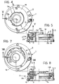
- FIGs 4 and 5 illustrate a simple variant of the transducer shown in Figures 1 to 3.
- a single fork, indicted 19 is used which carries a photoemitter 19a in its lower arm and two photodetectors 19b and 19c in radially offset positions ( Figure 5) in its upper arm.
- this "fork” there cooperates a ring 18 of transparent material, upon which opaque tracks such as those indicated T and T 2 in Figure 4 are deposited, for example by serigraphy. These tracks are at a radial distance from the axis of rotation of the rotor substantially equal to the radial distance separating this axis from the two photodetectors 19b, 19c.
- the transducer has two outputs (the outputs of the photodetectors) and is therefore a two-bit device.
- Figure 6 shows a further variant of the transducer according to the invention, in which a Hall-effect sensor 5 is fixed to the stator 1 and a magnet 30 in the form of a ring-sector is fixed to the rotor 2: in this case, the acceptable range of relative positions of the two members is defined by the intrinsic hysteresis of the sensor, while the extreme positions of this range are correlated to those conditions in which the magnet 30 is or is not in front of the sensor 50.
- FIGS 7 and 8 illustrate a variant of the transducer according to the invention with a five-bit output.
- five photoemitters 119 (which could be replaced by a single photoemitter of suitable size) are firmly connected to the stator 1 in radially adjacent positions and cooperate with five photodetectors 120 which face them in an ordered array.
- a ring 118 of transparent material fixed to the rotor 2.
- This ring has opaque and transparent sectors arranged according to a pre-established code in positions situated at radial distances from the axis of rotation of the rotor corresponding to the radial distances of the photodetectors 120. These opaque sectors are shown by hatching in Figure 6.
- the disc or ring 118, the photoemitters 119 and the photodetectors 120 together constitute a rotary optical encoder for detecting relative angular displacements between the rotor 2 and the stator 1.
- FIG. 9 shows a first "analog" version of the transducer according to the invention.
- a ring 38 carrying a track of resistive material, for example a thick-film resistor, indicated 39, on its upper surface is fixed to the stator 1.
- a sliding-contact member 40 is fixed to the rotor 2 in contact with the resistive track 39.
- This track and the contact member 40 together constitute a rotary potentiometer. If a potential difference is applied to the resistive element 39, the voltage between the brush 40 and one end of the resistive track 39 is a univocal function of the angular position of the rotor relative to the stator.
- FIGS 10 and 11 illustrate a second variant of an "analog" embodiment of the transducer according to the invention.
- an outwardly-facing Hall-effect sensor 50 is fixed to the stator 1.
- a magnet 51 in the form of a ring-sector is fixed to the rotor 2, facing the sensor 50.
- the magnet 51 which is constituted, for example, by a magnetoferrite, has a variable thickness in the radial direction of the rotor so that, from one of its ends to the other, its inner surface has a progressively increasing (or decreasing) radial spacing from the axis of rotation of the rotor. Consequently, when the rotor rotates relative to the stator, the signal output by the Hall-effect sensor 50 varies.
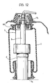
- Figure 12 shows a possible assembly of a transducer according to the invention, for detecting the degree of sliding of the shaft S relative to the cylinder C of a shock-absorber of a motor vehicle equipped with an automatic levelling system.
- variable-stiffness air springs such as that illustrated in Figure 12, arranged around the shock-absorber itself are used to effect the automatic levelling.
- the air spring comprises a flexible tubular casing I connected at its ends to two washers P1 and P2, of which the first, being fixed to the shaft S of the shock-absorber, is connected to the body, while the second, being fixed to the cylinder C of the shock-absorber, is connected to a.wheel.
- the transducer according to the invention is mounted within the casing I of the air spring: this casing therefore serves as a cover for the transducer.
- the traction cable 5 is connected to the upper washer by means of a very stiff spring 60.
- the electrical conductors for supplying and taking the signals from the transducer pass, for example, through at least one hole formed in the lower washer (in a manner not shown).
- the transducer may be mounted on the shock-asborber, as illustrated in Figure 1, or it may be mounted within an air spring with the stator rigid with one of the end washers and the traction cable connected to the other washer.
Abstract
Description
- The present invention relates to an electrical transducer for relative linear displacements between two members, particularly for automatic levelling devices for motor vehicle suspensions.
- The object of the invention is to provide an electrical transducer which is simple and cheap to manufacture and highly reliable.
- This object is achieved according to the invention by means of a transducer characterised in that it comprises:
- a fixed part or stator connectible to one of the two members,
- a movable part or rotor rotatably supported by the fixed part,
- a traction member having one end anchored to the other of the two members and its other end connected to the rotor in such a way as to cause its rotation in one sense relative to the stator when the members move away from each other,
- resilient return means which tend to rotate the rotor in the opposite sense of rotation when the two members move towards each other, and
- electrical sensor means for outputting electrical signals indicative of the angular position of the rotor relative to the stator.
- Further characteristics and advantages of the transducer according to the invention will be apparent from the detailed description which follows with reference to the appended drawings, provided purely by way of non-limiting example, in which:
- Figure 1 is a perspective view of a transducer according to the invention,
- Figure 2 is a perspective view of the transducer shown in Figure 1 in a first embodiment, without its upper covering element,
- Figure 3 is a partially-sectioned view taken on the line III-III of Figure 2,
- Figure 4 is a plan view of a variant of the sensor according to the invention,
- Figure 5 is a partially-sectioned view taken on the line V-V of Figure 4,
- Figure 6 is a plan view of a variant of the transducer,
- Figure 7 is a plan view of a further variant of the transducer according to the invention,
- Figure 8 is a partially-sectioned view taken on the line VIII-VIII of Figure 7,
- Figure 9 is a partially-sectioned elevational view of another variant of the transducer according to the invention,
- Figure 10 is a plan view of a further variant of the transducer according to the invention,
- Figure 11 is a partially-sectioned elevational view taken on line XI-XI of Figure 9, and
- Figure 12 is a sectional view of part of a motor vehicle suspension equipped with a transducer according to the invention.
- With reference to Figures 1 to 3, in a first embodiment a transducer according to the invention comprises a fixed part or
stator 1 and a movable part orrotor 2 supported rotatably by the fixed part. Thestator 1 has a tubular portion la (Figures 2 and 3) and an outer radial flange lb. Therotor 2 is annular and is rotatable about the tubular portion of the stator. This rotor has a recess 2a which houses a coil spring 3 (Figure 3) having one end fixed to the tubular portion la of the stator and its other end anchored to the rotor. - In the flange lb of the stator is formed an annular seat lc for
balls 4 intended to facilitate the relative sliding movement between the rotor and the stator (Figure 3). - A metal or nylon traction cable, indicated 5, has one end fixed to the
rotor 2 at one point of theannular groove 2b (not visible in the drawings). On the upper part of the stator flange lb is mounted asmall pulley 6 with its axis parallel to the plane of this flange, to ensure the return of thetraction cable 5. - During use, the
stator 1 is fixed to a first member while the free end of thetraction cable 5 is fixed to a second member whose displacement relative to the first is to be detected. In the application illustrated in Figure 1, the stator is connected to one end of the cylinder C of a telescopic shock-absorber, while thetraction cable 3 is connected to a washer P fixed to the shaft S of the shock-absorber. This shaft passes through the tubular portion la of the stator in a translatable manner. When the shock-absorber extends, that is lengthens, thetraction cable 5 causes a rotation of therotor 2 relative to thestator 1. When the shock-absorber contracts, however, thespring 3 tends to rotate therotor 2 in the opposite direction relative to the stator, and thetraction cable 5 is thus wound onto the rotor in theannular groove 2b. A relative displacement between the shaft S and the cylinder C causes a corresponding rotation of the rotor relative to the stator. - Conveniently, the circumference of the
groove 2b in the rotor correspoonds to the maximum length of the relative linear displacement to be detected. - In order to detect the relative rotation between the rotor and the stator in the embodiment shown in Figures 1 to 3, the upper part of the
rotor 2 carries a ring-sector 8 of opaque material and thestator 1 carries, in the upper part of the tubular portion la, two "forks" 9 and 10 the arms of which are positioned on opposite sides of the plane of thesector 8 and respectively accommodate a photoemitter and a photodetector which face each other. The photoemitter may be constituted, for example, by a light-emitting diode, while the photodetector may be constituted by a phototransistor. These are indicated 9a and 9b respectively in Figure 3. The outputs of the two photodetectors may be considered as the (two-bit digital) output of the transducer. - The transducer shown in Figures 1 to 3, if used in an automatic levelling system of a motor vehicle for signalling any variations in the attitude thereof, may indicate, for example, whether the height of the body from the ground falls within a pre-established range (the extent of this range being correlated with the angular extent of the sector 8), or whether such a height is outside the pre-established range. In the latter case, the transducer can indicate whether the value of the height is above or below the pre-established range.
- Figures 4 and 5 illustrate a simple variant of the transducer shown in Figures 1 to 3. According to this variant, instead of two photoemitter-photodetector "forks", a single fork, indicted 19, is used which carries a
photoemitter 19a in its lower arm and twophotodetectors ring 18 of transparent material, upon which opaque tracks such as those indicated T and T2 in Figure 4 are deposited, for example by serigraphy. These tracks are at a radial distance from the axis of rotation of the rotor substantially equal to the radial distance separating this axis from the twophotodetectors - Figure 6 shows a further variant of the transducer according to the invention, in which a Hall-
effect sensor 5 is fixed to thestator 1 and amagnet 30 in the form of a ring-sector is fixed to the rotor 2: in this case, the acceptable range of relative positions of the two members is defined by the intrinsic hysteresis of the sensor, while the extreme positions of this range are correlated to those conditions in which themagnet 30 is or is not in front of thesensor 50. - Figures 7 and 8 illustrate a variant of the transducer according to the invention with a five-bit output. "As apparent from Figure 8, in this variant five photoemitters 119 (which could be replaced by a single photoemitter of suitable size) are firmly connected to the
stator 1 in radially adjacent positions and cooperate with fivephotodetectors 120 which face them in an ordered array. Between thephotoemitters 119 and thephotodetectors 120 extends aring 118 of transparent material fixed to therotor 2. This ring has opaque and transparent sectors arranged according to a pre-established code in positions situated at radial distances from the axis of rotation of the rotor corresponding to the radial distances of thephotodetectors 120. These opaque sectors are shown by hatching in Figure 6. - In substance, the disc or
ring 118, thephotoemitters 119 and thephotodetectors 120 together constitute a rotary optical encoder for detecting relative angular displacements between therotor 2 and thestator 1. - Figure 9 shows a first "analog" version of the transducer according to the invention. In this version, a
ring 38 carrying a track of resistive material, for example a thick-film resistor, indicated 39, on its upper surface is fixed to thestator 1. A sliding-contact member 40 is fixed to therotor 2 in contact with theresistive track 39. This track and thecontact member 40 together constitute a rotary potentiometer. If a potential difference is applied to theresistive element 39, the voltage between thebrush 40 and one end of theresistive track 39 is a univocal function of the angular position of the rotor relative to the stator. - Figures 10 and 11 illustrate a second variant of an "analog" embodiment of the transducer according to the invention. In this variant, an outwardly-facing Hall-
effect sensor 50 is fixed to thestator 1. Amagnet 51 in the form of a ring-sector is fixed to therotor 2, facing thesensor 50. Themagnet 51, which is constituted, for example, by a magnetoferrite, has a variable thickness in the radial direction of the rotor so that, from one of its ends to the other, its inner surface has a progressively increasing (or decreasing) radial spacing from the axis of rotation of the rotor. Consequently, when the rotor rotates relative to the stator, the signal output by the Hall-effect sensor 50 varies. - Figure 12 shows a possible assembly of a transducer according to the invention, for detecting the degree of sliding of the shaft S relative to the cylinder C of a shock-absorber of a motor vehicle equipped with an automatic levelling system. In known manner, variable-stiffness air springs, such as that illustrated in Figure 12, arranged around the shock-absorber itself are used to effect the automatic levelling. In the embodiment shown in Figure 12, the air spring comprises a flexible tubular casing I connected at its ends to two washers P1 and P2, of which the first, being fixed to the shaft S of the shock-absorber, is connected to the body, while the second, being fixed to the cylinder C of the shock-absorber, is connected to a.wheel.
- Conveniently, the transducer according to the invention is mounted within the casing I of the air spring: this casing therefore serves as a cover for the transducer. The
traction cable 5 is connected to the upper washer by means of a verystiff spring 60. The electrical conductors for supplying and taking the signals from the transducer pass, for example, through at least one hole formed in the lower washer (in a manner not shown). - In some automatic levelling systems for motor vehicles, air springs are not always located around the respective shock-absorbers: in this case, the transducer may be mounted on the shock-asborber, as illustrated in Figure 1, or it may be mounted within an air spring with the stator rigid with one of the end washers and the traction cable connected to the other washer.
Claims (16)
Priority Applications (1)
| Application Number | Priority Date | Filing Date | Title |
|---|---|---|---|
| AT85830066T ATE57435T1 (en) | 1984-08-14 | 1985-03-13 | ELECTRICAL TRANSDUCER FOR LINEAR DISPLACEMENTS, PARTICULARLY FOR LEVEL CONTROLS ON MOTOR VEHICLE SUSPENSIONS. |
Applications Claiming Priority (2)
| Application Number | Priority Date | Filing Date | Title |
|---|---|---|---|
| IT6781884 | 1984-08-14 | ||
| IT67818/84A IT1179048B (en) | 1984-08-14 | 1984-08-14 | LINEAR MOVEMENT TRANSDUCER IN ELECTRIC SIGNALS PARTICULARLY FOR AUTOMATIC LEVELING DEVICES FOR SUSPENSIONS OF A VEHICLE |
Publications (3)
| Publication Number | Publication Date |
|---|---|
| EP0174914A2 true EP0174914A2 (en) | 1986-03-19 |
| EP0174914A3 EP0174914A3 (en) | 1987-05-27 |
| EP0174914B1 EP0174914B1 (en) | 1990-10-10 |
Family
ID=11305515
Family Applications (1)
| Application Number | Title | Priority Date | Filing Date |
|---|---|---|---|
| EP85830066A Expired - Lifetime EP0174914B1 (en) | 1984-08-14 | 1985-03-13 | Linear displacement-electrical signal transducer, particularly for automatic levelling devices for motor vehicle suspensions |
Country Status (5)
| Country | Link |
|---|---|
| US (1) | US4718683A (en) |
| EP (1) | EP0174914B1 (en) |
| AT (1) | ATE57435T1 (en) |
| DE (1) | DE3580079D1 (en) |
| IT (1) | IT1179048B (en) |
Cited By (6)
| Publication number | Priority date | Publication date | Assignee | Title |
|---|---|---|---|---|
| AU611502B2 (en) * | 1987-12-21 | 1991-06-13 | Pitney-Bowes Inc. | Hall effect printwheel encoder |
| AU611503B2 (en) * | 1987-12-21 | 1991-06-13 | Pitney-Bowes Inc. | Hall effect encoder apparatus |
| GB2385423A (en) * | 2002-01-16 | 2003-08-20 | Ctex Seat Comfort Ltd | A component position indicating system |
| WO2007088053A2 (en) | 2006-02-02 | 2007-08-09 | Sensor-Technik Wiedemann Gmbh | Measuring arrangement comprising a magnet |
| EP1873480A1 (en) * | 2006-06-29 | 2008-01-02 | Katimex Cielker GmbH | Testing and/or mounting device |
| US7969146B2 (en) | 2006-05-12 | 2011-06-28 | Parker-Hannifin Corporation | Displacement measurement device |
Families Citing this family (13)
| Publication number | Priority date | Publication date | Assignee | Title |
|---|---|---|---|---|
| US4822063A (en) * | 1987-11-27 | 1989-04-18 | Ford Motor Company | Automotive suspension control system including suspension position sensor |
| US5575577A (en) * | 1993-04-30 | 1996-11-19 | Canon Denshi Kabushiki Kaisha | Recording apparatus having position detecting device |
| US5560118A (en) * | 1994-10-26 | 1996-10-01 | Plummer; Lew E. | Linear position transducer |
| DE10110738C5 (en) * | 2001-03-01 | 2008-06-05 | ZF Lemförder GmbH | Ball joint, device for controlling operating parameters of a motor vehicle, steering linkage, tie rod and method for producing a ball joint |
| EP1431118A3 (en) * | 2002-12-17 | 2010-03-17 | Saia-Burgess Murten AG | Actuator for headlamp |
| US20050077691A1 (en) * | 2003-10-14 | 2005-04-14 | Witters Allen L. | Suspension structure with internal height sensor assembly |
| ITUD20070020A1 (en) * | 2007-02-02 | 2008-08-03 | C P G Internat S P A | DEVICE TO DETECT THE STRETCH OF A RIBBON |
| DE202010008058U1 (en) * | 2010-07-13 | 2011-10-19 | Kht Fahrzeugteile Gmbh | Linkage between a suspension and a rotation angle sensor connected to a control unit |
| DE102011089518A1 (en) * | 2011-12-22 | 2013-04-04 | Continental Automotive Gmbh | Apparatus and method for determining a position of an element |
| US9101519B2 (en) | 2013-02-07 | 2015-08-11 | Dallas Smith Corporation | Leveling ramp for a wheelchair |
| KR101898375B1 (en) * | 2016-01-29 | 2018-09-13 | 성균관대학교산학협력단 | Apparatus for measuring displacement of 6-axis |
| KR102554919B1 (en) * | 2016-12-15 | 2023-07-11 | 현대자동차주식회사 | Suspension apparatus able to adjusting vehucle height |
| US10131196B2 (en) * | 2017-01-12 | 2018-11-20 | GM Global Technology Operations LLC | Spring-damper assembly |
Citations (6)
| Publication number | Priority date | Publication date | Assignee | Title |
|---|---|---|---|---|
| US3160836A (en) * | 1960-07-01 | 1964-12-08 | Guerin Engineering Inc | Electrohydraulic actuator |
| US3888118A (en) * | 1973-03-02 | 1975-06-10 | Soiltest Inc | Method and apparatus for determining road roughness |
| US4121504A (en) * | 1977-01-21 | 1978-10-24 | Inovec, Inc. | Cylinder positioning systems |
| FR2467720A1 (en) * | 1979-10-19 | 1981-04-30 | Tokico Ltd | APPARATUS FOR ADJUSTING THE HEIGHT OF A VEHICLE |
| US4286386A (en) * | 1977-09-06 | 1981-09-01 | Long Irvin E | Electro-mechanical displacement measuring device |
| US4293837A (en) * | 1980-07-23 | 1981-10-06 | The Singer Company | Hall effect potentiometer |
Family Cites Families (6)
| Publication number | Priority date | Publication date | Assignee | Title |
|---|---|---|---|---|
| US1068290A (en) * | 1912-08-29 | 1913-07-22 | Paul Willmann | Spring-controlled mechanism. |
| US1114362A (en) * | 1913-03-18 | 1914-10-20 | Friedrich Huttenlocher | Indicator mechanism. |
| NL123252C (en) * | 1957-11-28 | |||
| CH374207A (en) * | 1958-09-25 | 1963-12-31 | Contraves Ag | Automatic measuring device for the current relative position of two mutually movable device parts |
| EP0033204A3 (en) * | 1980-01-26 | 1982-03-10 | Lucas Industries Plc | Suspension systems for vehicles |
| IT1129862B (en) * | 1980-11-17 | 1986-06-11 | Olivetti & Co Spa | OPTICAL TRANSDUCER |
-
1984
- 1984-08-14 IT IT67818/84A patent/IT1179048B/en active
-
1985
- 1985-03-13 DE DE8585830066T patent/DE3580079D1/en not_active Expired - Lifetime
- 1985-03-13 EP EP85830066A patent/EP0174914B1/en not_active Expired - Lifetime
- 1985-03-13 AT AT85830066T patent/ATE57435T1/en not_active IP Right Cessation
- 1985-06-13 US US06/744,437 patent/US4718683A/en not_active Expired - Fee Related
Patent Citations (6)
| Publication number | Priority date | Publication date | Assignee | Title |
|---|---|---|---|---|
| US3160836A (en) * | 1960-07-01 | 1964-12-08 | Guerin Engineering Inc | Electrohydraulic actuator |
| US3888118A (en) * | 1973-03-02 | 1975-06-10 | Soiltest Inc | Method and apparatus for determining road roughness |
| US4121504A (en) * | 1977-01-21 | 1978-10-24 | Inovec, Inc. | Cylinder positioning systems |
| US4286386A (en) * | 1977-09-06 | 1981-09-01 | Long Irvin E | Electro-mechanical displacement measuring device |
| FR2467720A1 (en) * | 1979-10-19 | 1981-04-30 | Tokico Ltd | APPARATUS FOR ADJUSTING THE HEIGHT OF A VEHICLE |
| US4293837A (en) * | 1980-07-23 | 1981-10-06 | The Singer Company | Hall effect potentiometer |
Cited By (12)
| Publication number | Priority date | Publication date | Assignee | Title |
|---|---|---|---|---|
| AU611502B2 (en) * | 1987-12-21 | 1991-06-13 | Pitney-Bowes Inc. | Hall effect printwheel encoder |
| AU611503B2 (en) * | 1987-12-21 | 1991-06-13 | Pitney-Bowes Inc. | Hall effect encoder apparatus |
| GB2385423A (en) * | 2002-01-16 | 2003-08-20 | Ctex Seat Comfort Ltd | A component position indicating system |
| US6768321B2 (en) | 2002-01-16 | 2004-07-27 | Ctex Seat Comfort Limited | Component position indicating apparatus |
| GB2385423B (en) * | 2002-01-16 | 2005-12-07 | Ctex Seat Comfort Ltd | Component position indicating apparatus |
| EP1335188A3 (en) * | 2002-01-16 | 2007-04-04 | Ctex Seat Comfort Ltd | Component position indicating apparatus |
| WO2007088053A2 (en) | 2006-02-02 | 2007-08-09 | Sensor-Technik Wiedemann Gmbh | Measuring arrangement comprising a magnet |
| WO2007088053A3 (en) * | 2006-02-02 | 2008-05-22 | Sensor Technik Wiedemann Gmbh | Measuring arrangement comprising a magnet |
| US8183855B2 (en) | 2006-02-02 | 2012-05-22 | Sensor-Technik Wiedemann Gmbh | Measuring arrangement comprising a magnet |
| EP1979716B1 (en) | 2006-02-02 | 2016-07-13 | Sensor-Technik Wiedemann GmbH | Measuring arrangement comprising a magnet |
| US7969146B2 (en) | 2006-05-12 | 2011-06-28 | Parker-Hannifin Corporation | Displacement measurement device |
| EP1873480A1 (en) * | 2006-06-29 | 2008-01-02 | Katimex Cielker GmbH | Testing and/or mounting device |
Also Published As
| Publication number | Publication date |
|---|---|
| ATE57435T1 (en) | 1990-10-15 |
| IT8467818A0 (en) | 1984-08-14 |
| EP0174914A3 (en) | 1987-05-27 |
| DE3580079D1 (en) | 1990-11-15 |
| EP0174914B1 (en) | 1990-10-10 |
| IT8467818A1 (en) | 1986-02-14 |
| IT1179048B (en) | 1987-09-16 |
| US4718683A (en) | 1988-01-12 |
Similar Documents
| Publication | Publication Date | Title |
|---|---|---|
| EP0174914B1 (en) | Linear displacement-electrical signal transducer, particularly for automatic levelling devices for motor vehicle suspensions | |
| US5491633A (en) | Position sensor for electromechanical suspension | |
| JP2537571B2 (en) | Steering axis direction and speed detector | |
| US5757180A (en) | Disk type of absolute-position magnetic encoder for rotary devices | |
| US5231876A (en) | Method and apparatus for wind speed and direction measurement | |
| CA1302543C (en) | Hall effect encoder apparatus | |
| JP2003516534A (en) | Device for measuring the angle and / or angular velocity of a rotating body and / or the torque acting on this rotating body | |
| FR2419506A1 (en) | MAGNETIC ROTARY ENCODER FOR THE DETECTION OF THE ABSOLUTE VALUES OF AN ANGULAR DISPLACEMENT | |
| JPH0530543U (en) | Bearing hub device | |
| JPH09178468A (en) | Angular sensor | |
| CN107850462A (en) | Rotary encoder | |
| US5585560A (en) | Sealed movement sensor | |
| EP0449671B1 (en) | Bearing with a magnetic field sensor | |
| US6528990B1 (en) | Magnetostrictive linear displacement transducer for a vehicle steering system | |
| AU731528B2 (en) | Measuring device for the contactless detection of a rotational angle | |
| US6236119B1 (en) | Device for determining the angular position of the steering wheel in a motor vehicle | |
| JPH0680957U (en) | Pack seal | |
| US5734160A (en) | Automobile steering angle sensor with a humidity moving member and a spiral shape resistance body | |
| EP1452434B1 (en) | Throttle position detecting apparatus | |
| US6501263B1 (en) | Rotary position sensor | |
| GB2284918A (en) | Inflation pressure sensor for a vehicle pneumatic tyre | |
| US6426618B1 (en) | Magnetostrictive linear displacement transducer for a vehicle steering system | |
| US4055090A (en) | Sensor | |
| EP1111628B1 (en) | Potentiometric position sensor subassembly | |
| JPH0526487Y2 (en) |
Legal Events
| Date | Code | Title | Description |
|---|---|---|---|
| PUAI | Public reference made under article 153(3) epc to a published international application that has entered the european phase |
Free format text: ORIGINAL CODE: 0009012 |
|
| AK | Designated contracting states |
Kind code of ref document: A2 Designated state(s): AT BE CH DE FR GB IT LI LU NL SE |
|
| PUAL | Search report despatched |
Free format text: ORIGINAL CODE: 0009013 |
|
| AK | Designated contracting states |
Kind code of ref document: A3 Designated state(s): AT BE CH DE FR GB IT LI LU NL SE |
|
| 17P | Request for examination filed |
Effective date: 19871113 |
|
| 17Q | First examination report despatched |
Effective date: 19890314 |
|
| GRAA | (expected) grant |
Free format text: ORIGINAL CODE: 0009210 |
|
| RAP1 | Party data changed (applicant data changed or rights of an application transferred) |
Owner name: MARELLI AUTRONICA S.P.A. |
|
| AK | Designated contracting states |
Kind code of ref document: B1 Designated state(s): AT BE CH DE FR GB IT LI LU NL SE |
|
| REF | Corresponds to: |
Ref document number: 57435 Country of ref document: AT Date of ref document: 19901015 Kind code of ref document: T |
|
| ITF | It: translation for a ep patent filed |
Owner name: JACOBACCI & PERANI S.P.A. |
|
| REF | Corresponds to: |
Ref document number: 3580079 Country of ref document: DE Date of ref document: 19901115 |
|
| ET | Fr: translation filed | ||
| PG25 | Lapsed in a contracting state [announced via postgrant information from national office to epo] |
Ref country code: GB Effective date: 19910313 Ref country code: AT Effective date: 19910313 |
|
| PG25 | Lapsed in a contracting state [announced via postgrant information from national office to epo] |
Ref country code: SE Effective date: 19910314 |
|
| PG25 | Lapsed in a contracting state [announced via postgrant information from national office to epo] |
Ref country code: LU Free format text: LAPSE BECAUSE OF NON-PAYMENT OF DUE FEES Effective date: 19910331 Ref country code: LI Effective date: 19910331 Ref country code: CH Effective date: 19910331 Ref country code: BE Effective date: 19910331 |
|
| PLBE | No opposition filed within time limit |
Free format text: ORIGINAL CODE: 0009261 |
|
| STAA | Information on the status of an ep patent application or granted ep patent |
Free format text: STATUS: NO OPPOSITION FILED WITHIN TIME LIMIT |
|
| BERE | Be: lapsed |
Owner name: MARELLI AUTRONICA S.P.A. Effective date: 19910331 |
|
| PG25 | Lapsed in a contracting state [announced via postgrant information from national office to epo] |
Ref country code: NL Effective date: 19911001 |
|
| 26N | No opposition filed | ||
| GBPC | Gb: european patent ceased through non-payment of renewal fee | ||
| NLV4 | Nl: lapsed or anulled due to non-payment of the annual fee | ||
| PG25 | Lapsed in a contracting state [announced via postgrant information from national office to epo] |
Ref country code: FR Effective date: 19911129 |
|
| REG | Reference to a national code |
Ref country code: CH Ref legal event code: PL |
|
| PG25 | Lapsed in a contracting state [announced via postgrant information from national office to epo] |
Ref country code: DE Effective date: 19920101 |
|
| REG | Reference to a national code |
Ref country code: FR Ref legal event code: ST |
|
| EUG | Se: european patent has lapsed |
Ref document number: 85830066.8 Effective date: 19911009 |