EP0173394B1 - Floor cleaning machine - Google Patents
Floor cleaning machine Download PDFInfo
- Publication number
- EP0173394B1 EP0173394B1 EP85201315A EP85201315A EP0173394B1 EP 0173394 B1 EP0173394 B1 EP 0173394B1 EP 85201315 A EP85201315 A EP 85201315A EP 85201315 A EP85201315 A EP 85201315A EP 0173394 B1 EP0173394 B1 EP 0173394B1
- Authority
- EP
- European Patent Office
- Prior art keywords
- lever
- motor
- cleaning machine
- floor cleaning
- brush
- Prior art date
- Legal status (The legal status is an assumption and is not a legal conclusion. Google has not performed a legal analysis and makes no representation as to the accuracy of the status listed.)
- Expired - Lifetime
Links
- 238000004140 cleaning Methods 0.000 title claims abstract description 24
- 230000001419 dependent effect Effects 0.000 claims description 4
- 230000001276 controlling effect Effects 0.000 abstract description 4
- 230000001105 regulatory effect Effects 0.000 abstract description 2
- 239000007788 liquid Substances 0.000 description 5
- 230000001680 brushing effect Effects 0.000 description 2
- 230000005355 Hall effect Effects 0.000 description 1
- 229960003832 ambazone Drugs 0.000 description 1
- MLMFUKWWZIZRHX-UHFFFAOYSA-N chembl2103762 Chemical compound NC(=N)NN=C1C=CC(=NNC(N)=S)C=C1 MLMFUKWWZIZRHX-UHFFFAOYSA-N 0.000 description 1
- 239000004020 conductor Substances 0.000 description 1
- 230000003247 decreasing effect Effects 0.000 description 1
- 238000010586 diagram Methods 0.000 description 1
- 238000005265 energy consumption Methods 0.000 description 1
- 239000012528 membrane Substances 0.000 description 1
- 238000000034 method Methods 0.000 description 1
- 239000004065 semiconductor Substances 0.000 description 1
- 238000000926 separation method Methods 0.000 description 1
Images


Classifications
-
- A—HUMAN NECESSITIES
- A47—FURNITURE; DOMESTIC ARTICLES OR APPLIANCES; COFFEE MILLS; SPICE MILLS; SUCTION CLEANERS IN GENERAL
- A47L—DOMESTIC WASHING OR CLEANING; SUCTION CLEANERS IN GENERAL
- A47L11/00—Machines for cleaning floors, carpets, furniture, walls, or wall coverings
- A47L11/40—Parts or details of machines not provided for in groups A47L11/02 - A47L11/38, or not restricted to one of these groups, e.g. handles, arrangements of switches, skirts, buffers, levers
- A47L11/4036—Parts or details of the surface treating tools
- A47L11/4038—Disk shaped surface treating tools
-
- A—HUMAN NECESSITIES
- A47—FURNITURE; DOMESTIC ARTICLES OR APPLIANCES; COFFEE MILLS; SPICE MILLS; SUCTION CLEANERS IN GENERAL
- A47L—DOMESTIC WASHING OR CLEANING; SUCTION CLEANERS IN GENERAL
- A47L11/00—Machines for cleaning floors, carpets, furniture, walls, or wall coverings
- A47L11/02—Floor surfacing or polishing machines
- A47L11/10—Floor surfacing or polishing machines motor-driven
- A47L11/14—Floor surfacing or polishing machines motor-driven with rotating tools
- A47L11/16—Floor surfacing or polishing machines motor-driven with rotating tools the tools being disc brushes
- A47L11/161—Floor surfacing or polishing machines motor-driven with rotating tools the tools being disc brushes with supply of cleaning agents
-
- A—HUMAN NECESSITIES
- A47—FURNITURE; DOMESTIC ARTICLES OR APPLIANCES; COFFEE MILLS; SPICE MILLS; SUCTION CLEANERS IN GENERAL
- A47L—DOMESTIC WASHING OR CLEANING; SUCTION CLEANERS IN GENERAL
- A47L11/00—Machines for cleaning floors, carpets, furniture, walls, or wall coverings
- A47L11/29—Floor-scrubbing machines characterised by means for taking-up dirty liquid
- A47L11/30—Floor-scrubbing machines characterised by means for taking-up dirty liquid by suction
- A47L11/302—Floor-scrubbing machines characterised by means for taking-up dirty liquid by suction having rotary tools
- A47L11/305—Floor-scrubbing machines characterised by means for taking-up dirty liquid by suction having rotary tools the tools being disc brushes
-
- A—HUMAN NECESSITIES
- A47—FURNITURE; DOMESTIC ARTICLES OR APPLIANCES; COFFEE MILLS; SPICE MILLS; SUCTION CLEANERS IN GENERAL
- A47L—DOMESTIC WASHING OR CLEANING; SUCTION CLEANERS IN GENERAL
- A47L11/00—Machines for cleaning floors, carpets, furniture, walls, or wall coverings
- A47L11/40—Parts or details of machines not provided for in groups A47L11/02 - A47L11/38, or not restricted to one of these groups, e.g. handles, arrangements of switches, skirts, buffers, levers
- A47L11/4002—Installations of electric equipment
-
- A—HUMAN NECESSITIES
- A47—FURNITURE; DOMESTIC ARTICLES OR APPLIANCES; COFFEE MILLS; SPICE MILLS; SUCTION CLEANERS IN GENERAL
- A47L—DOMESTIC WASHING OR CLEANING; SUCTION CLEANERS IN GENERAL
- A47L11/00—Machines for cleaning floors, carpets, furniture, walls, or wall coverings
- A47L11/40—Parts or details of machines not provided for in groups A47L11/02 - A47L11/38, or not restricted to one of these groups, e.g. handles, arrangements of switches, skirts, buffers, levers
- A47L11/4011—Regulation of the cleaning machine by electric means; Control systems and remote control systems therefor
Definitions
- the present invention relates to floor cleaning machines as defined as defined in the preamble of the accompanying Claim 1 and which are used for the cleaning of hard surfaces of large floor areas, such as e.g. in hotels, factories, office buildings, shopping centres and the like.
- a machine of this kind is disclosed in US-A-4218 798.
- such machines comprise a movable body supported by a pair of drive wheels and one or more caster wheels, the body carrying a brushing means, reservoirs for storing fresh and spent cleaning liquid, means for dosing fresh cleaning liquid onto the floor and a squeegee/vacuum pick-up system for recovering spent cleaning liquid from the floor.
- the brushing means normally comprises one or more rotatable brushes, a motor for driving the brushes and a means for lifting the brushes off the floor when large areas are traversed without any cleaning action being required.
- a number of conventional floor cleaning machines also include an option/for adjustment of the brush height with respect to the floor.
- adjustment of the brush height has to be done manually which severely limits the easy controllability during operation.
- the present invention provides a floor cleaning machine comprising a motor-driven movable body carrying a scrubber assembly which comprises a brush head housing one or more rotatable brushes, a motor for driving the brushes, a lever capable of lifting and lowering the brush head, a motor for moving the lever between a lifted and a lowered position in which the brushes engage the floor
- the scrubber assembly comprises a sensing device sensitive to the brush pressure which sends an output signal dependent upon the brush pressure , control means capable of comparing the output signal of the brush pressure sensing device with an operator-set value of the brush pressure, said control means being further capable of electrically controlling the operation of the lever motor to maintain the brush pressure at the operator-set value.
- control means comprises an electronic device which controls the lever motor by way of pulse width modulation.
- Pulse width modulation is a well-known method of controlling the motor voltage allowing easy electronic adjustment thereof to an operator-set value.
- the control means operates the lever motor on the basis of the feed-back output signal of the sensing device, which is proportional to the instant brush pressure.
- the sensing device will not measure the brush pressure directly, but by way of a related physical quantity proportional to the brush pressure, such as the deformation of parts or portions of parts of the scrubber assembly which are under a stress proportional to the brush pressure, or the instant power consumption of the lever motor.
- a preferred brush pressure sensing device consists of an ammeter which measures the amperage of the lever motor. Being proportional to the torque of the lever motor, this amperage is proportional to the brush pressure, accordingly providing a suitable feed back to the control means.
- the brush pressure sensing device comprises a deformation-sensitive component suitably attached to the surface of or incorporated in a stress-deformable portion of the lever or spring.
- the deformation-sensitive component may be any electrical or electronic device suitable for the purpose. Preferably it consists of a Hall element.
- a Hall element is a device which is based on the Hall effect whereby a transverse electromotive force is produced in a current-carrying conductor or semi-conductor subjected to a magnetic field.
- a deformation-dependent resistance strain gauge
- the lever is tensioned by an extension spring counter-acting the lever motor.
- the lever motor is a stepper motor.
- the brush pressure is proportional to the extension of the spring which in turn is linear to the number of steps of the stepper motor.
- a deformation-sensitive component may be incorporated in or connected to the extension spring for measuring the deformation thereof, which is proportional to the brush pressure.
- an automatic floor cleaning machine comprising a housing or body (1), a steering and controlling means (2), a scrubber assembly (3) and a squeegee (4).
- the body (1) has been drawn cut-open for illustration of the interior. It comprises a cover (5) for housing tank, battery, pump and motor parts.
- a storage tank (6) comprises a first reservoir(7) for storing fresh cleaning liquid and a second reservoir (8) for storing spent cleaning liquid.
- the two reservoirs may have a fixed separation wall, it is preferred that they are separated by way of a flexible membrane.
- the cleaning machine is supported on main drive wheels (9) and one or more caster wheels (10).
- the driving motor means for wheels (9) is battery-operated enabling ready manoeuverability over a wide area. Although the use of a battery is preferred, if so desired the motors may also be energized from an external electrical source through a cord, thereby eliminating battery (11).
- a brush head (12) houses two rotatable brushes (13) which are driven by motor means (14).
- the brush head (12) is carried by lever (15) comprising two arms (16) and (17) pivotably mounted on body (1) around pin pivot (18).
- elastic bearings (19) are mounted between the brush head and the lever arms.
- gear block (20) and lever (15) are spring-tensioned relative to each other by means of an extension spring (21) mounted between and to pegs (22) and (23).
- a peg stop (24) on gear block (20) is co-operable with arm (16) for preventing unrestricted backward movement of gear block (20) relative to lever (15).
- Pinion (25) is co-operable with gear block (20) for transmitting the drive-force of motor means (26) to the tension-force of spring (21).
- Motor means (26) is electrically connected to an electronic control unit (ECU) (27).
- ECU electronice control unit
- Clockwise or anti-clockwise rotation of pinion (25) results in a forward or backward pivoting movement of gear block (20) and, as a result, in an increased or decreased tension in extension spring (21).
- Proportional to the spring tension is the pressure exerted by lever (15) onto brush head (12) and accordingly, by the brushes onto the floor.
- a brush pressure sensing device (28) is attached to the lower portion of the lever arm (16).
- the sensoring device is of the type which is deformation-sensitive, such as a Hall element or a deformation-dependent resistance. With increasing brush pressure the lower portion of the lever arm (16) is proportionally deformed resulting in a proportional fed-back output signal of device (28) to the ECU (27), which on the basis thereof controls the operation, direction and power output of the lever motor means.
- the deformation of the extension spring (21) is measured to which purpose similar deformation-sensitive components may be used.
- FIG 3 a preferred control circuit for motor means (26) is illustrated.
- the ECU (27) controls the switches (29) and (30) which open and close the energizing circuit of the lever motor means and may establish inversal of the motor current. When no action is required the switches are in the closed position, motor means (26) being short-circuited and remaining in the instant position corresponding to the brush pressure as set by the operator. When the output signal of the brush pressure sensoring device (28) no longer corresponds to the, operator-set value, the ECU opens the appropriate switch (29) or (30) until the operator-set value is reached.
- the sensoring device comprises an ammeter which measures the amperage of the lever motor means (26). On a time-interval basis one of the switches (29) or (30) corresponding to lowering of lever (15), is opened and the amperage is measured which is necessary to maintain lever (15) in position. When the amperage does not correspond to the operator-set value, the ECU opens the appropriate switch (29) or (30) until the operator-set amperage is reached.
Landscapes
- Motor Or Generator Current Collectors (AREA)
- Vehicle Cleaning, Maintenance, Repair, Refitting, And Outriggers (AREA)
- Cleaning Of Streets, Tracks, Or Beaches (AREA)
- Pinball Game Machines (AREA)
- Electric Vacuum Cleaner (AREA)
- Cleaning In General (AREA)
Abstract
Description
- The present invention relates to floor cleaning machines as defined as defined in the preamble of the accompanying
Claim 1 and which are used for the cleaning of hard surfaces of large floor areas, such as e.g. in hotels, factories, office buildings, shopping centres and the like. A machine of this kind is disclosed in US-A-4218 798. In general such machines comprise a movable body supported by a pair of drive wheels and one or more caster wheels, the body carrying a brushing means, reservoirs for storing fresh and spent cleaning liquid, means for dosing fresh cleaning liquid onto the floor and a squeegee/vacuum pick-up system for recovering spent cleaning liquid from the floor. - The brushing means normally comprises one or more rotatable brushes, a motor for driving the brushes and a means for lifting the brushes off the floor when large areas are traversed without any cleaning action being required.
- A number of conventional floor cleaning machines also include an option/for adjustment of the brush height with respect to the floor. In general adjustment of the brush height has to be done manually which severely limits the easy controllability during operation.
- In view of uniform cleaning, wear of the brushes and energy consumption, it is often more advantageous to control not so much the brush heigth, but the brush pressure. In US patent No. 4,218,798 a control system has been disclosed whereby the brush pressure is operator-adjustable. Brush-pressure control is achieved by means of a hydraulic/pneumatic actuator system whereby the pressure level is adjustable by way of a pressure regulator.
- It is an object of the present invention to provide an electric brush-pressure regulating system. It is a further object to provide such a system for automatic control of the brush pressure which is instantly operator-adjustable.
- Accordingly, in its broadest aspect the present invention provides a floor cleaning machine comprising a motor-driven movable body carrying a scrubber assembly which comprises a brush head housing one or more rotatable brushes, a motor for driving the brushes, a lever capable of lifting and lowering the brush head, a motor for moving the lever between a lifted and a lowered position in which the brushes engage the floor characterized in that the scrubber assembly comprises a sensing device sensitive to the brush pressure which sends an output signal dependent upon the brush pressure , control means capable of comparing the output signal of the brush pressure sensing device with an operator-set value of the brush pressure, said control means being further capable of electrically controlling the operation of the lever motor to maintain the brush pressure at the operator-set value.
- In a first preferred aspect of the invention the control means comprises an electronic device which controls the lever motor by way of pulse width modulation. Pulse width modulation is a well-known method of controlling the motor voltage allowing easy electronic adjustment thereof to an operator-set value.
- Preferably, the control means operates the lever motor on the basis of the feed-back output signal of the sensing device, which is proportional to the instant brush pressure. In general the sensing device will not measure the brush pressure directly, but by way of a related physical quantity proportional to the brush pressure, such as the deformation of parts or portions of parts of the scrubber assembly which are under a stress proportional to the brush pressure, or the instant power consumption of the lever motor.
- A preferred brush pressure sensing device consists of an ammeter which measures the amperage of the lever motor. Being proportional to the torque of the lever motor, this amperage is proportional to the brush pressure, accordingly providing a suitable feed back to the control means.
- In a further preferred aspect of the invention the brush pressure sensing device comprises a deformation-sensitive component suitably attached to the surface of or incorporated in a stress-deformable portion of the lever or spring. The deformation-sensitive component may be any electrical or electronic device suitable for the purpose. Preferably it consists of a Hall element. A Hall element is a device which is based on the Hall effect whereby a transverse electromotive force is produced in a current-carrying conductor or semi-conductor subjected to a magnetic field. Instead of a Hall element a deformation-dependent resistance (strain gauge) may also advantageously be used.
- In a further aspect of the invention the lever is tensioned by an extension spring counter-acting the lever motor. Preferably the lever motor is a stepper motor. The brush pressure is proportional to the extension of the spring which in turn is linear to the number of steps of the stepper motor.
Suitably also, a deformation-sensitive component may be incorporated in or connected to the extension spring for measuring the deformation thereof, which is proportional to the brush pressure. - The invention will now be further illustrated with reference to the accompanying drawings in which:
- Figure 1 is a perspective view of an automatic cleaning machine according to the present invention;
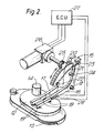
- Figure 2 is a perspective enlarged view of a preferred embodiment of the scrubber assembly according to the present invention; and
- Figure 3 is a circuit diagram showing a preferred control circuit for the lever motor means.
- Referring now to Figure 1 an automatic floor cleaning machine is shown, comprising a housing or body (1), a steering and controlling means (2), a scrubber assembly (3) and a squeegee (4). The body (1) has been drawn cut-open for illustration of the interior. It comprises a cover (5) for housing tank, battery, pump and motor parts. A storage tank (6) comprises a first reservoir(7) for storing fresh cleaning liquid and a second reservoir (8) for storing spent cleaning liquid. Although the two reservoirs may have a fixed separation wall, it is preferred that they are separated by way of a flexible membrane.
- The cleaning machine is supported on main drive wheels (9) and one or more caster wheels (10). The driving motor means for wheels (9) is battery-operated enabling ready manoeuverability over a wide area. Although the use of a battery is preferred, if so desired the motors may also be energized from an external electrical source through a cord, thereby eliminating battery (11).
- A preferred embodiment of the scrubber assembly (3) is shown in more detailed form in figure 2. A brush head (12) houses two rotatable brushes (13) which are driven by motor means (14). The brush head (12) is carried by lever (15) comprising two arms (16) and (17) pivotably mounted on body (1) around pin pivot (18). To allow small variations in position of brush head (12) with respect to lever (15), elastic bearings (19) are mounted between the brush head and the lever arms. Between the two arms (16) and (17) a gear block (20) is pivotably mounted about pin pivot (18). Gear block (20) and lever (15) are spring-tensioned relative to each other by means of an extension spring (21) mounted between and to pegs (22) and (23). A peg stop (24) on gear block (20) is co-operable with arm (16) for preventing unrestricted backward movement of gear block (20) relative to lever (15).
- Pinion (25) is co-operable with gear block (20) for transmitting the drive-force of motor means (26) to the tension-force of spring (21). Motor means (26) is electrically connected to an electronic control unit (ECU) (27). Clockwise or anti-clockwise rotation of pinion (25) results in a forward or backward pivoting movement of gear block (20) and, as a result, in an increased or decreased tension in extension spring (21). Proportional to the spring tension is the pressure exerted by lever (15) onto brush head (12) and accordingly, by the brushes onto the floor.
- By moving the gear block to its fully backward position the brush head is lifted off the floor due to cooperation of the peg stop (24) and lever arm (16). Accordingly control of the operation of lever motor means (26) gives full control of the brush pressure, and lifting or lowering of the brush head (12).
- A brush pressure sensing device (28) is attached to the lower portion of the lever arm (16). The sensoring device is of the type which is deformation-sensitive, such as a Hall element or a deformation-dependent resistance. With increasing brush pressure the lower portion of the lever arm (16) is proportionally deformed resulting in a proportional fed-back output signal of device (28) to the ECU (27), which on the basis thereof controls the operation, direction and power output of the lever motor means.
- In an alternative embodiment of the invention the deformation of the extension spring (21) is measured to which purpose similar deformation-sensitive components may be used.
- In figure 3 a preferred control circuit for motor means (26) is illustrated. The ECU (27) controls the switches (29) and (30) which open and close the energizing circuit of the lever motor means and may establish inversal of the motor current. When no action is required the switches are in the closed position, motor means (26) being short-circuited and remaining in the instant position corresponding to the brush pressure as set by the operator. When the output signal of the brush pressure sensoring device (28) no longer corresponds to the, operator-set value, the ECU opens the appropriate switch (29) or (30) until the operator-set value is reached.
- In an alternative embodiment of the invention the sensoring device comprises an ammeter which measures the amperage of the lever motor means (26). On a time-interval basis one of the switches (29) or (30) corresponding to lowering of lever (15), is opened and the amperage is measured which is necessary to maintain lever (15) in position. When the amperage does not correspond to the operator-set value, the ECU opens the appropriate switch (29) or (30) until the operator-set amperage is reached.
Claims (8)
- A floor cleaning machine comprising a motor-driven movable body (1) carrying a scrubber assembly (3) which comprises a brush head (12) housing one or more rotatable brushes (13), a motor (14) for driving the brushes (13), a lever (15) capable of lifting and lowering the brush head (12), and a motor (26) for moving the lever (15) between a lifted and a lowered position in which the brushes engage the floor, characterized in that the scrubber assembly (3) comprises a sensing device (28) sensitive to the brush pressure which sends an output signal dependent upon the brush pressure , control means (27) capable of comparing the output signal of the brush pressure sensing device (28) with an operator-set value of the brush pressure, said control means (27) being further capable of electrically controlling the operation of the lever motor (26) to maintain the brush pressure at the operator-set value.
- A floor cleaning machine according to claim 1 which comprises an extension spring (21) counter-acting the lever motor (26).
- A floor cleaning machine according to claim 2 in which the lever motor (26) is a stepper motor.
- A floor cleaning machine according to any one of the preceding claims wherein the control means (27) comprises an electronic device which controls the lever motor by way of pulse width modulation.
- A floor cleaning machine according to claim 1 wherein the brush pressure sensing device (28) consists of an ammeter capable of measuring the amperage of the lever motor.
- A floor cleaning machine according to claim 1 wherein the brush pressure sensing device (28) comprises a deformation-sensitive component suitably attached to the surface of or incorporated in a stress-deformable portion (19) of the lever (15) or spring (21).
- A floor cleaning machine according to claim 6 wherein the deformation-sensitive component comprises a Hall element.
- A floor cleaning machine according to claim 6 wherein the deformation-sensitive component comprises a strain gage.
Priority Applications (1)
| Application Number | Priority Date | Filing Date | Title |
|---|---|---|---|
| AT85201315T ATE69147T1 (en) | 1984-08-28 | 1985-08-16 | FLOOR CLEANING MACHINE. |
Applications Claiming Priority (2)
| Application Number | Priority Date | Filing Date | Title |
|---|---|---|---|
| GB848421713A GB8421713D0 (en) | 1984-08-28 | 1984-08-28 | Floor-cleaning machine |
| GB8421713 | 1984-08-28 |
Publications (3)
| Publication Number | Publication Date |
|---|---|
| EP0173394A2 EP0173394A2 (en) | 1986-03-05 |
| EP0173394A3 EP0173394A3 (en) | 1987-01-21 |
| EP0173394B1 true EP0173394B1 (en) | 1991-11-06 |
Family
ID=10565909
Family Applications (1)
| Application Number | Title | Priority Date | Filing Date |
|---|---|---|---|
| EP85201315A Expired - Lifetime EP0173394B1 (en) | 1984-08-28 | 1985-08-16 | Floor cleaning machine |
Country Status (7)
| Country | Link |
|---|---|
| US (1) | US4674142A (en) |
| EP (1) | EP0173394B1 (en) |
| JP (1) | JPS6172114A (en) |
| AT (1) | ATE69147T1 (en) |
| CA (1) | CA1257953A (en) |
| DE (1) | DE3584598D1 (en) |
| GB (1) | GB8421713D0 (en) |
Cited By (1)
| Publication number | Priority date | Publication date | Assignee | Title |
|---|---|---|---|---|
| US7448114B2 (en) | 2005-05-05 | 2008-11-11 | Tennant Company | Floor sweeping and scrubbing machine |
Families Citing this family (53)
| Publication number | Priority date | Publication date | Assignee | Title |
|---|---|---|---|---|
| US4679271A (en) * | 1986-03-14 | 1987-07-14 | Tennant Company | Automatic tool force compensator for a surface maintenance machine |
| US5264525A (en) * | 1986-08-28 | 1993-11-23 | National Starch And Chemical Investment Holding Corporation | Initiator compositions for two part acrylic adhesives |
| US4757566A (en) * | 1987-07-27 | 1988-07-19 | Tennant Company | Control of torque in floor maintenance tools by drive motor load |
| US4805258A (en) * | 1987-09-22 | 1989-02-21 | Tennant Trend Inc. | Battery powered walk behind floor burnisher |
| JP2807883B2 (en) * | 1987-11-17 | 1998-10-08 | アマノ株式会社 | Floor polishing machine |
| CN2041603U (en) * | 1988-08-16 | 1989-07-26 | 张朝吟 | Universal abrader |
| GB8907481D0 (en) * | 1989-04-03 | 1989-05-17 | Unilever Plc | Floor-cleaning machine |
| JPH0456457U (en) * | 1990-09-14 | 1992-05-14 | ||
| USD333018S (en) | 1990-10-15 | 1993-02-02 | Windsor Industries, Inc. | Floor polisher |
| US5177828A (en) * | 1991-08-20 | 1993-01-12 | Windsor Industries, Inc. | Missing pad detector for a floor polishing tool |
| US5265300A (en) * | 1992-01-13 | 1993-11-30 | Aar Corp. | Floor scrubber |
| DE69229670T2 (en) * | 1992-04-01 | 2000-01-27 | Penguin Wax Co. Ltd., Osaka | Soil treatment machine |
| CA2098151A1 (en) * | 1992-06-11 | 1993-12-12 | Russell S. Gurstein | Air cooled floor polishing machine |
| GB2283905B (en) * | 1993-11-17 | 1998-02-25 | Briscoe William A | Brush pressure system |
| GB2290021A (en) * | 1994-06-10 | 1995-12-13 | Briscoe William A | Brush pressure control system for floor cleaning machine |
| ATE171356T1 (en) * | 1993-11-17 | 1998-10-15 | Briscoe William A | BRUSH PRESSURE SYSTEM |
| JP3202474B2 (en) * | 1994-02-28 | 2001-08-27 | アマノ株式会社 | Floor polishing machine with pad pressure adjustment function |
| EP0678272A1 (en) * | 1994-04-20 | 1995-10-25 | Diethelm & Co. AG | Floor cleaning machines in particular surfacing or polishing machines |
| RU2151539C1 (en) * | 1994-06-10 | 2000-06-27 | Уильям Энтони Брискоу | Brush pressure regulating system |
| GB2305360A (en) * | 1995-09-06 | 1997-04-09 | William Anthony Briscoe | Brush pressure system for a floor cleaning machine |
| US5922968A (en) * | 1995-09-06 | 1999-07-13 | Briscoe; William Anthony | Brush pressure system |
| GB9703528D0 (en) * | 1996-09-04 | 1997-04-09 | Briscoe William A | Surface working apparatus |
| US5780088A (en) * | 1997-01-17 | 1998-07-14 | David R. Zittel | Electric motor driven abrasive roller peeler and cleaning machine |
| US6163915A (en) * | 1997-09-04 | 2000-12-26 | Minuteman International, Inc. | Control system for floor care machine |
| US6042656A (en) * | 1997-10-17 | 2000-03-28 | Nilfisk-Advance, Inc. | Shutoff control methods for surface treating machines |
| USRE39581E1 (en) * | 1997-10-22 | 2007-04-24 | Alto U.S., Inc. | Brush head positioning system |
| US5943724A (en) * | 1998-01-13 | 1999-08-31 | Tennant Company | Electro-hydraulic brush down force control |
| US6227957B1 (en) | 1998-05-22 | 2001-05-08 | Nilfisk-Advance, Inc. | Battery powered, riding, floor burnishing machine |
| US6450867B1 (en) | 1998-05-22 | 2002-09-17 | Nilfisk-Advance, Inc. | Battery powered, riding, floor treating machine |
| DE19959440C2 (en) * | 1999-12-09 | 2001-12-13 | Georg Hefter Maschb | Movable trolley, in particular work or floor cleaning machine |
| US6614195B2 (en) | 2000-05-09 | 2003-09-02 | Tennant Company | Linear actuator control structure |
| US6763544B2 (en) | 2000-08-22 | 2004-07-20 | Alto Us, Inc. | Apparatus for treating a floor surface |
| US6557207B2 (en) | 2000-08-22 | 2003-05-06 | Alto U.S. Inc. | Squeegee assembly for a floor surface treatment apparatus |
| US6760947B2 (en) | 2000-08-22 | 2004-07-13 | Alto U.S. Inc. | Apparatus for treating a floor surface utilizing a handle mounted traverse switch |
| US6986397B2 (en) * | 2002-03-01 | 2006-01-17 | Floorstyle Products, Inc. | Power riding trailer for an implement |
| US20040200017A1 (en) * | 2003-04-10 | 2004-10-14 | Crane Joylon M. | Surface maintenance tool power control system |
| ITMI20031080A1 (en) * | 2003-05-29 | 2004-11-30 | Dulevo Int Spa | CONTROL DEVICE OF A REVOLVING BRUSH, |
| US8234749B2 (en) * | 2005-01-11 | 2012-08-07 | Nilfisk-Advance, Inc. | Orbital scrubber with stabilizer element |
| US20060150362A1 (en) * | 2005-01-11 | 2006-07-13 | Alto U.S. Inc. | Orbital scrubber |
| WO2007087598A1 (en) * | 2006-01-25 | 2007-08-02 | Johnsondiversey, Inc. | A device and method for adjusting the pressure between a floor cleaning implement and a floor |
| WO2010110796A1 (en) * | 2009-03-26 | 2010-09-30 | Nilfisk-Advance, Inc. | Flow and scrubbing pressure control system and methods for surface treating apparatus |
| EP2814371B1 (en) * | 2012-02-16 | 2018-06-06 | Tennant Company | Surface maintenance vehicle with compact cleaning head lift mechanism and suspension |
| CN103799928B (en) * | 2012-11-07 | 2016-09-07 | 芜湖爱瑞特环保科技有限公司 | A disc brush translation mechanism |
| ITMI20122256A1 (en) * | 2012-12-28 | 2014-06-29 | Sir Soc It Riduttori S R L | MECHANICAL ORGAN |
| ITMI20122257A1 (en) * | 2012-12-28 | 2014-06-29 | Sir Soc It Riduttori S R L | METHOD FOR THE CONTROL OF AN ACTUATOR |
| CN108042231B (en) * | 2018-01-30 | 2023-08-22 | 深圳市云顶信息技术有限公司 | electric toothbrush |
| CN109730588B (en) * | 2019-01-31 | 2024-04-09 | 深圳和而泰智能控制股份有限公司 | Floor wiping robot |
| CN110952488B (en) * | 2019-12-31 | 2021-08-13 | 福建龙马环卫装备股份有限公司 | An automatic control circuit for sweeping discs that can automatically adapt to various road conditions |
| CN111719482A (en) * | 2020-06-23 | 2020-09-29 | 北京京环装备设计研究院有限公司 | Control method, device and system of water tank truck |
| USD1000023S1 (en) * | 2020-10-14 | 2023-09-26 | Alfred Kaercher Se & Co. Kg | Machine for cleaning floors |
| USD1006355S1 (en) * | 2021-01-21 | 2023-11-28 | Alfred Kaercher Se & Co. Kg | Floor cleaning device |
| CN117490779B (en) * | 2024-01-03 | 2024-03-01 | 珠海格力电器股份有限公司 | Rolling brush detection method and device, cleaning device, electronic equipment and storage medium |
| DE102024135212A1 (en) * | 2024-11-28 | 2026-05-28 | Dr. Gansow Gmatic AG | scrubber-dryer |
Family Cites Families (9)
| Publication number | Priority date | Publication date | Assignee | Title |
|---|---|---|---|---|
| US2978719A (en) * | 1957-12-30 | 1961-04-11 | Advance Machine Co | Mobile floor treating machine |
| US3712399A (en) * | 1970-07-13 | 1973-01-23 | Dugard C Ltd | Battery power control device |
| US3818292A (en) * | 1972-11-17 | 1974-06-18 | Energy Dev Ass | Electronic accelerator control for electric vehicle |
| DE2303614C2 (en) * | 1973-01-25 | 1975-03-20 | Kleindienst & Co, Maschinenfabrik, 8900 Augsburg | Device for controlling the brush evasive movement in an arrangement for washing vehicles |
| DE2348899A1 (en) * | 1973-09-28 | 1975-04-10 | Kleindienst & Co | Pressure controlled brush for car wash - has two coaxial sections joined by torsion coupling and driven by single drive shaft |
| US4218798A (en) * | 1979-06-19 | 1980-08-26 | Clarke-Gravely Corporation | Floor treating machine |
| JPS57127482A (en) * | 1981-01-28 | 1982-08-07 | Shin Meiwa Ind Co Ltd | Washer for machine body |
| DD212180A1 (en) * | 1982-12-02 | 1984-08-08 | Oberlind Veb Elektroinstall | SWITCHING DEVICE FOR FLOOR VACUUM CLEANER |
| US4490873A (en) * | 1983-10-24 | 1985-01-01 | Stratton Harry M | Floating-brush assembly for use with floor-scrubbing and polishing machines |
-
1984
- 1984-08-28 GB GB848421713A patent/GB8421713D0/en active Pending
-
1985
- 1985-08-16 DE DE8585201315T patent/DE3584598D1/en not_active Expired - Fee Related
- 1985-08-16 EP EP85201315A patent/EP0173394B1/en not_active Expired - Lifetime
- 1985-08-16 AT AT85201315T patent/ATE69147T1/en not_active IP Right Cessation
- 1985-08-21 CA CA000489146A patent/CA1257953A/en not_active Expired
- 1985-08-21 US US06/767,877 patent/US4674142A/en not_active Expired - Fee Related
- 1985-08-26 JP JP60187169A patent/JPS6172114A/en active Granted
Cited By (2)
| Publication number | Priority date | Publication date | Assignee | Title |
|---|---|---|---|---|
| US7448114B2 (en) | 2005-05-05 | 2008-11-11 | Tennant Company | Floor sweeping and scrubbing machine |
| US7665174B2 (en) | 2005-05-05 | 2010-02-23 | Tennant Company | Cleaning head for use in a floor cleaning machine |
Also Published As
| Publication number | Publication date |
|---|---|
| EP0173394A3 (en) | 1987-01-21 |
| DE3584598D1 (en) | 1991-12-12 |
| JPS6172114A (en) | 1986-04-14 |
| EP0173394A2 (en) | 1986-03-05 |
| GB8421713D0 (en) | 1984-10-03 |
| JPH0414207B2 (en) | 1992-03-12 |
| US4674142A (en) | 1987-06-23 |
| ATE69147T1 (en) | 1991-11-15 |
| CA1257953A (en) | 1989-08-01 |
Similar Documents
| Publication | Publication Date | Title |
|---|---|---|
| US4674142A (en) | Floor cleaning machine | |
| EP0928846B1 (en) | Electro-hydraulic brush down force control | |
| EP3641524B1 (en) | Speed control assembly | |
| US5673450A (en) | Brush pressure system | |
| US4506405A (en) | Floor treating machine | |
| FI86593C (en) | GOLVRENINGSMASKIN MED FOERBAETTRAD KONTROLL FOER BORSTTRYCKET. | |
| EP0301437B1 (en) | Control of torque in floor maintenance tools by drive motor load | |
| US4667364A (en) | Floor-cleaning machine | |
| US20090020356A1 (en) | Steering device for floor cleaning machine | |
| CA1259460A (en) | Floor cleaning machine | |
| EP0502451B1 (en) | Electronic torque wrench and overshoot compensation circuit therefor | |
| WO2003002017B1 (en) | Automatic electric toothbrush | |
| WO2002094077A1 (en) | Control system for a floor maintenance appliance | |
| EP1009274A1 (en) | System for adjusting the brush pressure | |
| WO1997008984A1 (en) | Brush pressure system | |
| EP1983876B1 (en) | A device and method for adjusting the pressure between a floor cleaning implement and a floor | |
| EP1600095B1 (en) | Back EMF actuator control | |
| US4330007A (en) | Potentiometer and switch control arrangement | |
| JP2688977B2 (en) | Field hardness detection device for agricultural machinery | |
| GB1581231A (en) | Wheelchairs | |
| WO1981003209A1 (en) | Potentiometer and switch control arrangement | |
| GB2290021A (en) | Brush pressure control system for floor cleaning machine | |
| JPS6240204A (en) | Working machine lifting/falling apparatus of tractor | |
| JPH01152168U (en) |
Legal Events
| Date | Code | Title | Description |
|---|---|---|---|
| PUAI | Public reference made under article 153(3) epc to a published international application that has entered the european phase |
Free format text: ORIGINAL CODE: 0009012 |
|
| AK | Designated contracting states |
Kind code of ref document: A2 Designated state(s): AT BE CH DE FR GB IT LI NL SE |
|
| PUAL | Search report despatched |
Free format text: ORIGINAL CODE: 0009013 |
|
| AK | Designated contracting states |
Kind code of ref document: A3 Designated state(s): AT BE CH DE FR GB IT LI NL SE |
|
| 17P | Request for examination filed |
Effective date: 19870102 |
|
| 17Q | First examination report despatched |
Effective date: 19880812 |
|
| GRAA | (expected) grant |
Free format text: ORIGINAL CODE: 0009210 |
|
| AK | Designated contracting states |
Kind code of ref document: B1 Designated state(s): AT BE CH DE FR GB IT LI NL SE |
|
| PG25 | Lapsed in a contracting state [announced via postgrant information from national office to epo] |
Ref country code: BE Effective date: 19911106 Ref country code: AT Effective date: 19911106 |
|
| REF | Corresponds to: |
Ref document number: 69147 Country of ref document: AT Date of ref document: 19911115 Kind code of ref document: T |
|
| REF | Corresponds to: |
Ref document number: 3584598 Country of ref document: DE Date of ref document: 19911212 |
|
| ET | Fr: translation filed | ||
| ITF | It: translation for a ep patent filed | ||
| PLBE | No opposition filed within time limit |
Free format text: ORIGINAL CODE: 0009261 |
|
| STAA | Information on the status of an ep patent application or granted ep patent |
Free format text: STATUS: NO OPPOSITION FILED WITHIN TIME LIMIT |
|
| 26N | No opposition filed | ||
| PGFP | Annual fee paid to national office [announced via postgrant information from national office to epo] |
Ref country code: FR Payment date: 19930713 Year of fee payment: 9 |
|
| PGFP | Annual fee paid to national office [announced via postgrant information from national office to epo] |
Ref country code: CH Payment date: 19930714 Year of fee payment: 9 |
|
| PGFP | Annual fee paid to national office [announced via postgrant information from national office to epo] |
Ref country code: SE Payment date: 19930719 Year of fee payment: 9 |
|
| PGFP | Annual fee paid to national office [announced via postgrant information from national office to epo] |
Ref country code: DE Payment date: 19930721 Year of fee payment: 9 |
|
| PGFP | Annual fee paid to national office [announced via postgrant information from national office to epo] |
Ref country code: GB Payment date: 19930729 Year of fee payment: 9 |
|
| PGFP | Annual fee paid to national office [announced via postgrant information from national office to epo] |
Ref country code: NL Payment date: 19930831 Year of fee payment: 9 |
|
| PG25 | Lapsed in a contracting state [announced via postgrant information from national office to epo] |
Ref country code: GB Effective date: 19940816 |
|
| PG25 | Lapsed in a contracting state [announced via postgrant information from national office to epo] |
Ref country code: SE Effective date: 19940817 |
|
| PG25 | Lapsed in a contracting state [announced via postgrant information from national office to epo] |
Ref country code: LI Effective date: 19940831 Ref country code: CH Effective date: 19940831 |
|
| EAL | Se: european patent in force in sweden |
Ref document number: 85201315.0 |
|
| PG25 | Lapsed in a contracting state [announced via postgrant information from national office to epo] |
Ref country code: NL Effective date: 19950301 |
|
| GBPC | Gb: european patent ceased through non-payment of renewal fee |
Effective date: 19940816 |
|
| NLV4 | Nl: lapsed or anulled due to non-payment of the annual fee | ||
| PG25 | Lapsed in a contracting state [announced via postgrant information from national office to epo] |
Ref country code: FR Effective date: 19950428 |
|
| REG | Reference to a national code |
Ref country code: CH Ref legal event code: PL |
|
| PG25 | Lapsed in a contracting state [announced via postgrant information from national office to epo] |
Ref country code: DE Effective date: 19950503 |
|
| EUG | Se: european patent has lapsed |
Ref document number: 85201315.0 |
|
| REG | Reference to a national code |
Ref country code: FR Ref legal event code: ST |