EP0173372A2 - Sitting furniture, in particular a swivel-chair - Google Patents
Sitting furniture, in particular a swivel-chair Download PDFInfo
- Publication number
- EP0173372A2 EP0173372A2 EP85201214A EP85201214A EP0173372A2 EP 0173372 A2 EP0173372 A2 EP 0173372A2 EP 85201214 A EP85201214 A EP 85201214A EP 85201214 A EP85201214 A EP 85201214A EP 0173372 A2 EP0173372 A2 EP 0173372A2
- Authority
- EP
- European Patent Office
- Prior art keywords
- seat
- sitting furniture
- furniture according
- clamping
- bar
- Prior art date
- Legal status (The legal status is an assumption and is not a legal conclusion. Google has not performed a legal analysis and makes no representation as to the accuracy of the status listed.)
- Granted
Links
Images


Classifications
-
- A—HUMAN NECESSITIES
- A47—FURNITURE; DOMESTIC ARTICLES OR APPLIANCES; COFFEE MILLS; SPICE MILLS; SUCTION CLEANERS IN GENERAL
- A47C—CHAIRS; SOFAS; BEDS
- A47C1/00—Chairs adapted for special purposes
- A47C1/02—Reclining or easy chairs
- A47C1/031—Reclining or easy chairs having coupled concurrently adjustable supporting parts
- A47C1/032—Reclining or easy chairs having coupled concurrently adjustable supporting parts the parts being movably-coupled seat and back-rest
- A47C1/03261—Reclining or easy chairs having coupled concurrently adjustable supporting parts the parts being movably-coupled seat and back-rest characterised by elastic means
- A47C1/03288—Reclining or easy chairs having coupled concurrently adjustable supporting parts the parts being movably-coupled seat and back-rest characterised by elastic means with resilient blocks
-
- A—HUMAN NECESSITIES
- A47—FURNITURE; DOMESTIC ARTICLES OR APPLIANCES; COFFEE MILLS; SPICE MILLS; SUCTION CLEANERS IN GENERAL
- A47C—CHAIRS; SOFAS; BEDS
- A47C1/00—Chairs adapted for special purposes
- A47C1/02—Reclining or easy chairs
- A47C1/031—Reclining or easy chairs having coupled concurrently adjustable supporting parts
- A47C1/032—Reclining or easy chairs having coupled concurrently adjustable supporting parts the parts being movably-coupled seat and back-rest
- A47C1/03255—Reclining or easy chairs having coupled concurrently adjustable supporting parts the parts being movably-coupled seat and back-rest with a central column, e.g. rocking office chairs
Definitions
- the invention relates to a sitting furniture according to the preamble of claim l.Such a sitting furniture is known from laid-open German Patent Application No.3,315,273 of applicant.This known sitting furniture has been found useful in practice.
- the object of the present invention is to provide a further development of this known sitting furniture.
- this object is achieved by the provisions shown in claim 1.It is thus possible to integrate the rotary spring in the frame of the sitting furniture, making a corresponding area for mounting a spring underneath of this seat superfluous.
- Under rotary spring is understood in this connection an element, that will oppose a twisting of two construction elements with respect to each other by elastic resistance, and will create return force, wchich increases with increasing displacement-angle.
- the action of the rotary spring may be supported by a corresponding seat-guide in the area of the front seat end.
- the seat-guide is made according to claim 5, in order to obtain in the working position and in the rest-position always an ergonomically advantageous seat-position.
- the seat-position is preferably provided according to claim 6, as an about horizontal, or even sligtly forward sloping seat-position is advantageous during work, while a backward sloping seat-position in the rest-position prevents slipping of the user from the sitting furniture and thus is experienced as pleasant.
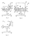
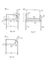
- FIGS 1-3 show schematically a swivel-chair 10 according to the invention, with a turn-cross 11 of customary construction, that is connected with a box-like, internally hollow cross-support 13 by means of a column 12, serving for height adjustment, the support 13 serving for the incorpor- poration of a blocking-device.
- a frame 15 is connected, having at both sides of the seat each a horizontal section 16 ending in a mounting 17, and a section 18, rising under an angle of about 45 0 , the latter ending in a mounting 19.
- the mountings 19 serve for turnable hinging an uphol stered back-piece 22, which is connected at its lower end with a seat-piece 24 by means of a hinge-joint 23.
- a bar 25 is running transverse to the seat 24 at its front segment, both ends of bar 25 being hinged in the mountings 17 longitudinally displaceable by means of seat-guides.
- a rotary spring is located, which aims to turn the back-piece in the direction of arrow 26 (Fig.1), when the chair is not occupied and the blocking-device is disengaged.Thus the chair is pulled in its working position, and this so long until the cross-bar 25 bumps against a cam in mounting 17.This working position is shown in Fig.l.
- the back-piece 22 turns in the direction of the clock (with reference to Fig.l or 3) by a pressure of the shoulders at 27 against it, then the seat-piece 24 is shifted forward, until the cross-bar 25 bumps against its front cam in mounting 17, and at the same time the rotary springs in the mountings 19 are pressed together, thus tightened.
- This is the relaxation position of the swivel-chair 10, which also in the foolowing will be referred to as relaxation position and which is shown in Fig.3. If the seat is not blocked in this relaxation position, then it wll return automatically after disburdening to the working position according to Fig.l, while the rotary springs in the mountings 19 be partially released.
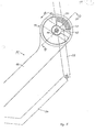
- Figs.4 and 5 show the frame 15 of the swivel-chair 10 with its horizontal section 16, its mounting 17, the rising section 18 and its mounting 19.
- the seat 24 and the back-piece 22 are shown in dash-dotted lines schematically in their working position (similar to Fig.l).
- a seat-guide 30 in the form of an oblique longitudinal hole 31, which guides the cross-bar 25, so that the seat 24 when shifted forward, that is in the direction of arrow 33, is lifted, whereby a corresponding opposite force is created.
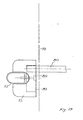
- a rotary spring 35 is positioned in mounting 19 .
- a mounting 37 is attached to the back 22 by means of two screws 36, 36' according to Fig.9 said mounting 37 extending into a free space 39 by means of a catch 38, said free space comprising a shaped piece 40 of an elastomer, e.g.
- the shaped piece 40 rests with one end against a radially extending wall 42 of the mounting 19, connected with the rising section 18, while its other end lies against the catch 38.
- the catch 38 turns correspondingly in the free space 39 and presses the shaped piece elastically together and against the wall 42, so that the opposite force, described above, is created in the direction of the aroow 26.
- the mounting 19 is attached rotably to the mounting 37 by means of a screw 44.
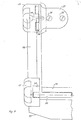
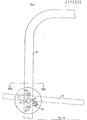
- a blocking-device 45 is positioned in the cross-support 13, said blocking device being released by means of an operating handle 46, the end of which is presented in Fig.2 at 47, while an operating handle for the adjustment in height is shown there at 48.
- the handle 46 is rotably hinged at a.bearing-frame 49.
- the bearing-frame 49 is attached at the cross-support 13.Thus when the operating handle 47 (Fig.2) is pulled upward by the user, the handle 46 in Fig.8 will turn around the bearing-frame 49 against the direction of the clock, so that its interior, free end 46', with reference to Fig.8, will go downward.
- the end 46' is positioned between two clamping-elements 52, 53, which according to Figs.4 and 6 are each hinged at the bearing-frames 56, 57 by means of two turned offwelds 52', 52" and 53', 53" respectively and corresponding shafts 54, 55.
- the bearing-frames 56, 57 are attached to cross-support 13, comp. in particular Fig.8.
- Fig.4 narrows the intermediate area between the.clamping-elements 52, 53 downward, and the free end 46' of the operating handle 46 is dimensioned in such a manner, that on turning it downward the ends of the clamping-elements 52, 53 located there are forced away from each other
- the clamping-element 52 is turned in the direction of the clock and the clamping-element 53 against the direction of the clock around the shafts 54 and 55 respectively.
- a spring-device 60 Between the upper ends of the clamping-elements 52, 53 is a spring-device 60, here in the shape of a block of a suitable elastomer.
- the spring-device 60 presses these ends apart into their blocking-position, while on activation of the handle 46 these ends are turned in the direction towards each other - against the force of the spring-device 60 - whereby the blocking is released.
- each one of the two clamping-elements 52, 53 has a rectangularly shaped free space 61, through which extends a bar 62 of polygonal cross-section.
- this cross-section is of square shape.
- the bar 62 is connected with a mounting 64 by means of a shaft 63, which in turn is attached to the seat 24, and actually the shaft 63 runs through a longitudinal hole 64' of mounting 64, so that a displacement in height of the seat 24 has no effect on the movements of the bar 62.
- the clamping-element 52 blocks in blocked position a movement of the bar 62 towards the left, while the clamping-element 53 blocks a movement of the bar 62 towards the right. If however the operating handle 46 is turned, so that its handle-end 46' moves downward, then the blocking is released.
- the clamping-elements 52 and 53 are advantageously hardened in the area of their free spaces 61.A blocking of seat 24 in any desired positione is possible by them, and thus a blocking in both directions of displacement.
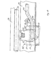
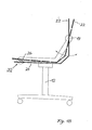
- Figs.10 to 17 show a second example of the invention in the form of a desk-chair 70 (visitors chair) with a four legged frame 71, consisting of two about U-shaped frames 72, 73 and a cross-connection 74.
- the frames 72, 73 may have an about oval side-view, but may be also e.g. circlecylindrical, square, etc.Two mountings 75, 76 are attached to each one of the frames 72, 73.
- the mounting 76 serves for connecting a back 77, which is connected with a seat 79 by means of a hinge 78.
- the mounting 76 comprises, just as the mounting 13 of Figs.l to 9, a rotary spring in the sense of the definition given in the introduction.
- the mounting 75 is similarly composed as the mounting 17 of Figs.l to 9,"and serves here as well for the longitudinal guidance of the seat 79 and to its lifting on forward displacement. If the seat 79 is shifted into its relaxation position (rest position) according to Fig.12, then the rotary spring in the mounting 76 is put under tension, so that on release of the cair 70 it will move back its parts into their working position according to Fig.10.
- a cross-bar 80 is provided at the bottom side of the seat 79, which is connected to the seat 79 and both ends of which are each positioned movable in an inclined longitudinal hole 83 of the mounting 75.
- the mounting 75 is' attached as shown to frames 72 and 73 respectively by means of two screws 84, 84'.
- the frames 72, 73 are further provided with a hole 85 each in the area of the mounting 75, in order to allow the introduction of the cross-bar 80 during assembly
- a mounting part 90 is attached to the back 77 by means of two screws 88, 89, said mounting part 90 showing a catch 93 in the shape of a sector of a circle, which extends into a corresponding free space 94 of the mounting 76.
- This free space 94 is provided with a radially extending cross-wall 95 against which one end of a part 96 of an elastomeric material is resting, the other end of which is resting against the catch 93.
- the catch 93 is moved in the direc tion of the clock, then it presses the part 96 elastically together, so that a corresponding opposite force is created, which tends to turn the back part 77 in the direction of the arrow 99 (Fig.14) into its working position (Fig.10).
- a screw 102 For attachment of the mounting 76 (which according to Fig.15 fits on the frame 73) and of the mounting part 90 on the frame 73 (respectively on the other side on frame 72) serves a screw 102, which is screwed into a screw-thread case 103 welded in into the frame 73 (72 respectively), which keeps the mounting part 90 at the mounting 76, and allows a turning of the mounting part 79 with respect to the mounting 76.
- Fig.18 shows schematically the modification of the inclination of the seat 24 in various seat-positions.
- the working position according to Fig.1 is shown in full lines, in which the back 22 is about vertical.
- the seat 24 has an bout horizontal position, or is slightly inclined forward, as this is ergonomically favourable during work.
- the seat-guide 30 When reverting to the rest position, presented with dashed lines, the seat-guide 30 causes, that the seat 24 assumes a slight inclination backward, in order to prevent a slipping out from the sitting furniture.Thus one obtains continuously an ergonomically favourable working position.
- the seat-guide 30 causes only a slight lifting herein.
- a chair is thus obtained with very simple means, having outstanding use properties and an aesthetically pleasant, light and elegant appearance.
Abstract
Description
- The invention relates to a sitting furniture according to the preamble of claim l.Such a sitting furniture is known from laid-open German Patent Application No.3,315,273 of applicant.This known sitting furniture has been found useful in practice.
- The object of the present invention is to provide a further development of this known sitting furniture.
- According to the invention this object is achieved by the provisions shown in claim 1.It is thus possible to integrate the rotary spring in the frame of the sitting furniture, making a corresponding area for mounting a spring underneath of this seat superfluous.Under rotary spring is understood in this connection an element, that will oppose a twisting of two construction elements with respect to each other by elastic resistance, and will create return force, wchich increases with increasing displacement-angle.The action of the rotary spring may be supported by a corresponding seat-guide in the area of the front seat end.
- Preferably the seat-guide is made according to claim 5, in order to obtain in the working position and in the rest-position always an ergonomically advantageous seat-position.To that end the seat-position is preferably provided according to claim 6, as an about horizontal, or even sligtly forward sloping seat-position is advantageous during work, while a backward sloping seat-position in the rest-position prevents slipping of the user from the sitting furniture and thus is experienced as pleasant.
- Further details and advantageous additional developments of the invention will follow from the embodiments as described hereafter and shown in the drawings, which should not be considered in any way as a limitation of the invention as well as the sub-claims.It is shown in :
- Fig.1 as first embod-iment of the invention a swivel-chair in side-view and in working position,
- Fig.2 the chair according to Fig.1 in front-view,
- Fig.3 a presentation corresponding with Fig.l, in which the chair is in its relaxation position (rest-position),
- Fig.4 a section, seen along the line IV-IV of Fig.2, at an enlarged scale; this section corresponds about with the excised section A, shown with dash-dotted lines in Fig.l,
- Fig.5 a view corresponding about with the excised section B, shown with dash-dotted lines in Fig.l,
- Fig.6 a top view of the blicking-device, seen along the arrows VI-VI of Fig.4,
- Fig.7 a front view, corresponding about with the excised section D of Fig.2,
- Fig.8 a section, seen along the line VIII-VIII of Fig.4, and corresponding about with the excised section E of Fig.2,
- Fig.9 a section seen along the line IX-IX of Fig.5,
- Fig.10 as second embodiment a side-view of a desk-chair according to the invention in working position,
- Fig.11 a front view of the desk-chair of Fig.10,
- Fig.12 a side-view corresponding with Fig.10, but in relaxation position (rest position),
- Fig.13 a section, seen along the line XIII-XIII of Fig.16, which shows the seat-guidance by means of a sloping longitudinal hole,
- Fig.14 a section, seen along the line XIV-XIV of Fig.16, through the rotary spring,
- Fig.15 a section, seen along the line XV-XV of Fig.14,
- Fig.16 a front view corresponding about with the excised section H, shown with dash-dotted lines in Fig.11,
- Fig.17 a top view, seen along the line XVII-XVII of Fig.13, and this on a mounting accepting the seat-guide, and
- Fig.18 a schematic presentation of the change of the slope of the seat while changing from the working position to the rest-position.
- In the description hereafter identical or similar functioning parts are usually indicated with the same reference number and are usually described only once.
- The Figures 1-3 show schematically a swivel-
chair 10 according to the invention, with a turn-cross 11 of customary construction, that is connected with a box-like, internallyhollow cross-support 13 by means of acolumn 12, serving for height adjustment, thesupport 13 serving for the incorpor- poration of a blocking-device. - At the cross-support 13 a
frame 15 is connected, having at both sides of the seat each ahorizontal section 16 ending in amounting 17, and asection 18, rising under an angle of about 450, the latter ending in amounting 19. - The
mountings 19 serve for turnable hinging an uphol stered back-piece 22, which is connected at its lower end with a seat-piece 24 by means of a hinge-joint 23.A bar 25 is running transverse to theseat 24 at its front segment, both ends ofbar 25 being hinged in themountings 17 longitudinally displaceable by means of seat-guides.In both mountings 19 a rotary spring is located, which aims to turn the back-piece in the direction of arrow 26 (Fig.1), when the chair is not occupied and the blocking-device is disengaged.Thus the chair is pulled in its working position, and this so long until thecross-bar 25 bumps against a cam in mounting 17.This working position is shown in Fig.l. - When on the other hand the back-
piece 22 turns in the direction of the clock (with reference to Fig.l or 3) by a pressure of the shoulders at 27 against it, then the seat-piece 24 is shifted forward, until thecross-bar 25 bumps against its front cam in mounting 17, and at the same time the rotary springs in themountings 19 are pressed together, thus tightened.This is the relaxation position of the swivel-chair 10, which also in the foolowing will be referred to as relaxation position and which is shown in Fig.3.If the seat is not blocked in this relaxation position, then it wll return automatically after disburdening to the working position according to Fig.l, while the rotary springs in themountings 19 be partially released. - Figs.4 and 5 show the
frame 15 of the swivel-chair 10 with itshorizontal section 16, itsmounting 17, the risingsection 18 and its mounting 19.In addition theseat 24 and the back-piece 22 are shown in dash-dotted lines schematically in their working position (similar to Fig.l). - In
mounting 17 is a seat-guide 30 in the form of an obliquelongitudinal hole 31, which guides thecross-bar 25, so that theseat 24 when shifted forward, that is in the direction ofarrow 33, is lifted, whereby a corresponding opposite force is created. - In mounting 19 a rotary spring 35 is positioned.To this end a
mounting 37 is attached to theback 22 by means of twoscrews 36, 36' according to Fig.9 said mounting 37 extending into afree space 39 by means of acatch 38, said free space comprising ashaped piece 40 of an elastomer, e.g. rubber.According to Fig.5 theshaped piece 40 rests with one end against a radially extendingwall 42 of themounting 19, connected with the risingsection 18, while its other end lies against the catch 38.When in Fig.5 theback 22 is turned in the direction of the clock, the thecatch 38 turns correspondingly in thefree space 39 and presses the shaped piece elastically together and against thewall 42, so that the opposite force, described above, is created in the direction of thearoow 26. - As the Figures 5 and 9 show in addition, the
mounting 19 is attached rotably to themounting 37 by means of ascrew 44. - A blocking-
device 45 is positioned in thecross-support 13, said blocking device being released by means of anoperating handle 46, the end of which is presented in Fig.2 at 47, while an operating handle for the adjustment in height is shown there at 48.Thehandle 46 is rotably hinged at a.bearing-frame 49.The bearing-frame 49 is attached at the cross-support 13.Thus when the operating handle 47 (Fig.2) is pulled upward by the user, thehandle 46 in Fig.8 will turn around the bearing-frame 49 against the direction of the clock, so that its interior, free end 46', with reference to Fig.8, will go downward. - The end 46' is positioned between two clamping-
elements frames offwelds 52', 52" and 53', 53" respectively andcorresponding shafts 54, 55.The bearing-frames cross-support 13, comp. in particular Fig.8. - According to Fig.4 narrows the intermediate area between the.clamping-
elements operating handle 46 is dimensioned in such a manner, that on turning it downward the ends of the clamping-elements element 52 is turned in the direction of the clock and the clamping-element 53 against the direction of the clock around theshafts - Between the upper ends of the clamping-
elements handle 46 these ends are turned in the direction towards each other - against the force of the spring-device 60 - whereby the blocking is released. - According to Fig.8 each one of the two clamping-
elements bar 62 of polygonal cross-section. In the example this cross-section is of square shape.As Figs. 4 and 6 show, thebar 62 is connected with amounting 64 by means of ashaft 63, which in turn is attached to theseat 24, and actually theshaft 63 runs through a longitudinal hole 64' of mounting 64, so that a displacement in height of theseat 24 has no effect on the movements of thebar 62. - As shown in Fig.4, the clamping-
element 52 blocks in blocked position a movement of thebar 62 towards the left, while the clamping-element 53 blocks a movement of thebar 62 towards the right.If however theoperating handle 46 is turned, so that its handle-end 46' moves downward, then the blocking is released.The clamping-elements seat 24 in any desired positione is possible by them, and thus a blocking in both directions of displacement. - The Figs.10 to 17 show a second example of the invention in the form of a desk-chair 70 (visitors chair) with a four legged
frame 71, consisting of two aboutU-shaped frames frames mountings frames 72, 73.Themounting 76 serves for connecting aback 77, which is connected with aseat 79 by means of ahinge 78. - The
mounting 76 comprises, just as themounting 13 of Figs.l to 9, a rotary spring in the sense of the definition given in the introduction.Themounting 75 is similarly composed as themounting 17 of Figs.l to 9,"and serves here as well for the longitudinal guidance of theseat 79 and to its lifting on forward displacement.If theseat 79 is shifted into its relaxation position (rest position) according to Fig.12, then the rotary spring in themounting 76 is put under tension, so that on release of the cair 70 it will move back its parts into their working position according to Fig.10. - In addition a
cross-bar 80 is provided at the bottom side of theseat 79, which is connected to theseat 79 and both ends of which are each positioned movable in an inclinedlongitudinal hole 83 of the mounting 75.Themounting 75 is' attached as shown to frames 72 and 73 respectively by means of twoscrews frames hole 85 each in the area of themounting 75, in order to allow the introduction of thecross-bar 80 during assembly - The construction of the
mounting 76 with the rotary spring follows from the Figures 14-16.According to Figs.15 and 16 amounting part 90 is attached to theback 77 by means of twoscrews part 90 showing acatch 93 in the shape of a sector of a circle, which extends into a correspondingfree space 94 of the mounting 76.Thisfree space 94 is provided with a radially extendingcross-wall 95 against which one end of apart 96 of an elastomeric material is resting, the other end of which is resting against the catch 93.If now in Fig.14 thecatch 93 is moved in the direc tion of the clock, then it presses thepart 96 elastically together, so that a corresponding opposite force is created, which tends to turn theback part 77 in the direction of the arrow 99 (Fig.14) into its working position (Fig.10). - For attachment of the mounting 76 (which according to Fig.15 fits on the frame 73) and of the
mounting part 90 on the frame 73 (respectively on the other side on frame 72) serves ascrew 102, which is screwed into a screw-thread case 103 welded in into the frame 73 (72 respectively), which keeps the mountingpart 90 at themounting 76, and allows a turning of the mountingpart 79 with respect to themounting 76. - In the second example according to Figures 10-17 no blocking-device is shown.Such an arrangement could however be provided if needed also for this embodiment.
- Fig.18 shows schematically the modification of the inclination of the
seat 24 in various seat-positions.The working position according to Fig.1 is shown in full lines, in which theback 22 is about vertical.Theseat 24 has an bout horizontal position, or is slightly inclined forward, as this is ergonomically favourable during work. - When reverting to the rest position, presented with dashed lines, the seat-
guide 30 causes, that theseat 24 assumes a slight inclination backward, in order to prevent a slipping out from the sitting furniture.Thus one obtains continuously an ergonomically favourable working position. The seat-guide 30 causes only a slight lifting herein. - According to the invention a chair is thus obtained with very simple means, having outstanding use properties and an aesthetically pleasant, light and elegant appearance.
- Within the scope of the prsent invention numerous variations and modifications are of course possible for those versed in the art, without going beyond the limits set by the specification and the claims.
Claims (17)
Priority Applications (1)
| Application Number | Priority Date | Filing Date | Title |
|---|---|---|---|
| AT85201214T ATE50127T1 (en) | 1984-08-08 | 1985-07-19 | SEATING FURNITURE, ESPECIALLY SWIVEL CHAIR. |
Applications Claiming Priority (2)
| Application Number | Priority Date | Filing Date | Title |
|---|---|---|---|
| DE3429186 | 1984-08-08 | ||
| DE3429186A DE3429186A1 (en) | 1984-08-08 | 1984-08-08 | SEAT, IN PARTICULAR OFFICE CHAIR |
Publications (3)
| Publication Number | Publication Date |
|---|---|
| EP0173372A2 true EP0173372A2 (en) | 1986-03-05 |
| EP0173372A3 EP0173372A3 (en) | 1986-12-03 |
| EP0173372B1 EP0173372B1 (en) | 1990-02-07 |
Family
ID=6242600
Family Applications (1)
| Application Number | Title | Priority Date | Filing Date |
|---|---|---|---|
| EP85201214A Revoked EP0173372B1 (en) | 1984-08-08 | 1985-07-19 | Sitting furniture, in particular a swivel-chair |
Country Status (6)
| Country | Link |
|---|---|
| US (1) | US4732424A (en) |
| EP (1) | EP0173372B1 (en) |
| JP (1) | JPS61247418A (en) |
| AT (1) | ATE50127T1 (en) |
| CA (1) | CA1236764A (en) |
| DE (2) | DE3429186A1 (en) |
Cited By (3)
| Publication number | Priority date | Publication date | Assignee | Title |
|---|---|---|---|---|
| EP0539377A1 (en) * | 1990-04-10 | 1993-05-05 | Charles O. Perry | High density stacking flex chair |
| US5383712A (en) * | 1988-04-25 | 1995-01-24 | Perry; Charles O. | Flexible chair |
| US6224159B1 (en) | 1999-05-12 | 2001-05-01 | Charles Owen Perry | Flexible chair which can be disassembled to a flat configuration |
Families Citing this family (37)
| Publication number | Priority date | Publication date | Assignee | Title |
|---|---|---|---|---|
| DE3844102A1 (en) * | 1988-12-28 | 1990-07-05 | Sondergeld Horst Dipl Designer | SEAT FOR AN OFFICE CHAIR OD. DGL. |
| US5338094A (en) * | 1988-04-25 | 1994-08-16 | Perry Charles O | Flexible reclining chair |
| WO1989010080A1 (en) * | 1988-04-25 | 1989-11-02 | Perry Charles O | Reclining chair |
| DE3838999A1 (en) * | 1988-11-18 | 1990-05-23 | Roeder Gmbh | CHAIR, ESPECIALLY WORK OR OFFICE CHAIR |
| US4979778A (en) * | 1989-01-17 | 1990-12-25 | Brayton International, Inc. | Synchrotilt chair |
| DE4027730A1 (en) * | 1990-09-01 | 1992-03-12 | Braeutigam Moebel Product Mark | Seat unit with incline or height adjustable seat - has non-metal spring elements forming adjustment elements |
| JPH0825414B2 (en) * | 1991-12-05 | 1996-03-13 | タカタ株式会社 | Restraint protection sheet for infants |
| DE19634665A1 (en) * | 1996-08-28 | 1998-03-05 | Jungjohann Thomas | Seating furniture element, in particular upholstered furniture element, with a coupled backrest and seat adjustment |
| DE19639741C2 (en) * | 1996-09-06 | 1998-07-09 | Thomas Jungjohann | Seating furniture element, in particular upholstered furniture element, with a coupled backrest and seat adjustment |
| US6334648B1 (en) * | 1997-03-21 | 2002-01-01 | Girsberger Holding Ag | Vehicle seat |
| US5979984A (en) * | 1997-10-24 | 1999-11-09 | Steelcase Development Inc. | Synchrotilt chair with forwardly movable seat |
| ES2161117B1 (en) * | 1998-11-10 | 2002-06-16 | Figueras Int Seating Sa | ARMCHAIR WITH BACKREST AND FOLDING FOOTBALL. |
| US6709058B1 (en) | 1999-04-09 | 2004-03-23 | Humanscale Corp. | Ergonomic chair |
| US6293616B1 (en) * | 2000-01-10 | 2001-09-25 | Ford Global Technologies, Inc. | Modular rail for roof and windshield |
| US6722735B2 (en) * | 2001-04-16 | 2004-04-20 | Ditto Sales, Inc. | Chair with synchronously moving seat and seat back |
| AU2003281505A1 (en) * | 2002-07-23 | 2004-02-09 | Okamura Corporation | Chair |
| US7341233B2 (en) * | 2003-09-19 | 2008-03-11 | L & P Property Management Company | Horizontal adjustment mechanism for use on a chair seat |
| US6969116B2 (en) * | 2003-12-30 | 2005-11-29 | Hni Technologies Inc. | Chair with backward and forward passive tilt capabilities |
| JP2007537003A (en) * | 2004-05-13 | 2007-12-20 | ヒューマンスケール コーポレイション | Chair with column base with membrane panel |
| US7325873B2 (en) * | 2004-06-12 | 2008-02-05 | Steelcase Inc. | Seating unit |
| US7159942B2 (en) * | 2004-08-26 | 2007-01-09 | L & P Property Management Company | Seat slide adjustment mechanism |
| DE202005001166U1 (en) * | 2005-01-24 | 2005-03-31 | Bock 1 Gmbh & Co Kg | Synchronous mechanism for an office chair comprises a base support arranged on a chair column, a seat or seat support and a backrest support |
| US7478880B2 (en) | 2005-03-08 | 2009-01-20 | L&P Property Management Company | Multi-purpose adjustment chair mechanism |
| USD623449S1 (en) | 2005-05-13 | 2010-09-14 | Humanscale Corporation | Mesh backrest for a chair |
| US8061775B2 (en) * | 2005-06-20 | 2011-11-22 | Humanscale Corporation | Seating apparatus with reclining movement |
| GB0517384D0 (en) * | 2005-08-26 | 2005-10-05 | Birkbeck Hilary R | Variable configuration seating |
| US20070222266A1 (en) * | 2006-03-21 | 2007-09-27 | Ditto Sales, Inc. | Nestable and stackable chair |
| USD661135S1 (en) | 2006-06-20 | 2012-06-05 | Humanscale Corporation | Pair of armrests for a chair or the like |
| US7896439B2 (en) * | 2006-08-30 | 2011-03-01 | Itoki Corporation | Chair |
| JP2011092475A (en) * | 2009-10-30 | 2011-05-12 | Itoki Corp | Rocking chair |
| JP2011092474A (en) * | 2009-10-30 | 2011-05-12 | Itoki Corp | Rocking chair |
| EP2348226A1 (en) * | 2010-01-22 | 2011-07-27 | Stoll Giroflex AG | Elastomer torsion spring element, device for transferring force with same and seat device with a device for transferring force |
| US20130175841A1 (en) * | 2012-01-11 | 2013-07-11 | James W. Finck | Reclining seat assembly |
| US9504326B1 (en) | 2012-04-10 | 2016-11-29 | Humanscale Corporation | Reclining chair |
| US9801471B2 (en) | 2014-04-17 | 2017-10-31 | Hni Technologies Inc. | Chair and chair control assemblies, systems, and methods |
| DE112019007468T5 (en) * | 2019-06-17 | 2022-02-24 | Quali Co., Ltd. | Adjustable chair |
| NL2026485B1 (en) | 2020-09-16 | 2022-05-16 | Npk Design B V | Adjustable chair |
Citations (6)
| Publication number | Priority date | Publication date | Assignee | Title |
|---|---|---|---|---|
| US3337266A (en) * | 1966-02-01 | 1967-08-22 | Belvedere Products Inc | Compensating back chair |
| US3536358A (en) * | 1968-12-11 | 1970-10-27 | Peter F Masucci | Slideable seat construction |
| GB1343305A (en) * | 1971-04-01 | 1974-01-10 | Werner P G | Adjustable resiliently hinged device for chairs and the like |
| US3934932A (en) * | 1971-10-28 | 1976-01-27 | J.E. Ekornes Fabrikker A/S | Adjustable chair |
| WO1983003957A1 (en) * | 1982-05-19 | 1983-11-24 | Ami | Articulated seat |
| DE3315237A1 (en) * | 1983-04-27 | 1984-10-31 | Angela 4592 Lindern Uredat-Neuhoff | Seating furniture, in particular an office chair |
Family Cites Families (8)
| Publication number | Priority date | Publication date | Assignee | Title |
|---|---|---|---|---|
| US601035A (en) * | 1898-03-22 | Adjustable chair | ||
| GB224687A (en) * | 1923-10-17 | 1924-11-20 | David Edward Turner | Improvements in tip-up chairs and the like |
| US2400588A (en) * | 1943-11-19 | 1946-05-21 | Reconstruction Finance Corp | Seat |
| US2611421A (en) * | 1950-12-13 | 1952-09-23 | American Airmotive Corp | Adjustable seat and back rest chair construction |
| FR1466417A (en) * | 1965-12-01 | 1967-01-20 | Publicite Francaise | Mechanical locking device and its applications, in particular to adjustable seats |
| BE799878A (en) * | 1973-01-24 | 1973-09-17 | Lusch Ferdinand | ADJUSTABLE LONG CHAIR |
| DE3036993A1 (en) * | 1980-10-01 | 1982-05-13 | Wilkhahn Wilkening + Hahne GmbH + Co, 3252 Bad Münder | WORK SEAT |
| US4504090A (en) * | 1982-10-20 | 1985-03-12 | Goldman Paul R | Swivel, tilt and recline arm chair |
-
1984
- 1984-08-08 DE DE3429186A patent/DE3429186A1/en not_active Withdrawn
-
1985
- 1985-07-19 EP EP85201214A patent/EP0173372B1/en not_active Revoked
- 1985-07-19 DE DE8585201214T patent/DE3575853D1/en not_active Revoked
- 1985-07-19 AT AT85201214T patent/ATE50127T1/en not_active IP Right Cessation
- 1985-08-06 CA CA000488127A patent/CA1236764A/en not_active Expired
- 1985-08-07 JP JP60173957A patent/JPS61247418A/en active Pending
-
1987
- 1987-05-01 US US07/052,136 patent/US4732424A/en not_active Expired - Fee Related
Patent Citations (6)
| Publication number | Priority date | Publication date | Assignee | Title |
|---|---|---|---|---|
| US3337266A (en) * | 1966-02-01 | 1967-08-22 | Belvedere Products Inc | Compensating back chair |
| US3536358A (en) * | 1968-12-11 | 1970-10-27 | Peter F Masucci | Slideable seat construction |
| GB1343305A (en) * | 1971-04-01 | 1974-01-10 | Werner P G | Adjustable resiliently hinged device for chairs and the like |
| US3934932A (en) * | 1971-10-28 | 1976-01-27 | J.E. Ekornes Fabrikker A/S | Adjustable chair |
| WO1983003957A1 (en) * | 1982-05-19 | 1983-11-24 | Ami | Articulated seat |
| DE3315237A1 (en) * | 1983-04-27 | 1984-10-31 | Angela 4592 Lindern Uredat-Neuhoff | Seating furniture, in particular an office chair |
Cited By (5)
| Publication number | Priority date | Publication date | Assignee | Title |
|---|---|---|---|---|
| US5383712A (en) * | 1988-04-25 | 1995-01-24 | Perry; Charles O. | Flexible chair |
| USRE36335E (en) * | 1988-04-25 | 1999-10-12 | Perry; Charles O. | Flexible chair |
| EP0539377A1 (en) * | 1990-04-10 | 1993-05-05 | Charles O. Perry | High density stacking flex chair |
| EP0539377A4 (en) * | 1990-04-10 | 1993-06-16 | Charles O. Perry | High density stacking flex chair |
| US6224159B1 (en) | 1999-05-12 | 2001-05-01 | Charles Owen Perry | Flexible chair which can be disassembled to a flat configuration |
Also Published As
| Publication number | Publication date |
|---|---|
| EP0173372B1 (en) | 1990-02-07 |
| DE3429186A1 (en) | 1986-02-20 |
| DE3575853D1 (en) | 1990-03-15 |
| US4732424A (en) | 1988-03-22 |
| CA1236764A (en) | 1988-05-17 |
| EP0173372A3 (en) | 1986-12-03 |
| ATE50127T1 (en) | 1990-02-15 |
| JPS61247418A (en) | 1986-11-04 |
Similar Documents
| Publication | Publication Date | Title |
|---|---|---|
| EP0173372A2 (en) | Sitting furniture, in particular a swivel-chair | |
| US4695093A (en) | Work chair | |
| DE60215709T2 (en) | office chair | |
| DE2820063C2 (en) | chair | |
| EP0079530B1 (en) | Lockable rocking device for seats of sitting furniture | |
| US6135556A (en) | Seat adjustment mechanism | |
| EP0638265B1 (en) | Office chair | |
| US20140117736A1 (en) | Adjustable armrest for a seating unit | |
| DE8529359U1 (en) | Seating | |
| CA2724761A1 (en) | Back rest for a stool or a chair, and stool or chair provided with such a back rest | |
| DE2930268C2 (en) | chair | |
| EP1039815B1 (en) | Chair with adjustment mechanism | |
| DE19848074A1 (en) | Seat with movable seat surface having adjustable tilt angle on pivot point, between foot and seat surface, and back rest | |
| EP0622995A1 (en) | Resilient chair support | |
| DE19709481C2 (en) | Movable armrest especially for computer workstations | |
| DE3744363A1 (en) | CHAIR, ESPECIALLY WORK OR OFFICE CHAIR | |
| EP1774871A1 (en) | Device for adjusting a seating furniture to the body weight and the centre of gravity of a person | |
| DE4406225A1 (en) | Chair with rigid base element and upholstered seat | |
| US20020041118A1 (en) | Chair tilting mechanism and a chair incorporating such a mechanism | |
| CA1324313C (en) | Rocking chair | |
| JP6909355B2 (en) | Seat module and tilt mechanism | |
| DE4027730C2 (en) | ||
| DE102005002431B3 (en) | Seat has a base, seating part which can move forward or backward on base and adjustable rest for the feet and/or shins of user tilted using an adjustment plate | |
| CH657510A5 (en) | WORK CHAIR. | |
| DE3348491C2 (en) | Adjustable chair that can be adjusted to your height |
Legal Events
| Date | Code | Title | Description |
|---|---|---|---|
| PUAI | Public reference made under article 153(3) epc to a published international application that has entered the european phase |
Free format text: ORIGINAL CODE: 0009012 |
|
| AK | Designated contracting states |
Kind code of ref document: A2 Designated state(s): AT BE CH DE FR GB IT LI LU NL SE |
|
| PUAL | Search report despatched |
Free format text: ORIGINAL CODE: 0009013 |
|
| AK | Designated contracting states |
Kind code of ref document: A3 Designated state(s): AT BE CH DE FR GB IT LI LU NL SE |
|
| 17P | Request for examination filed |
Effective date: 19870522 |
|
| 17Q | First examination report despatched |
Effective date: 19880621 |
|
| GRAA | (expected) grant |
Free format text: ORIGINAL CODE: 0009210 |
|
| AK | Designated contracting states |
Kind code of ref document: B1 Designated state(s): AT BE CH DE FR GB IT LI LU NL SE |
|
| PG25 | Lapsed in a contracting state [announced via postgrant information from national office to epo] |
Ref country code: SE Effective date: 19900207 Ref country code: AT Effective date: 19900207 |
|
| REF | Corresponds to: |
Ref document number: 50127 Country of ref document: AT Date of ref document: 19900215 Kind code of ref document: T |
|
| REF | Corresponds to: |
Ref document number: 3575853 Country of ref document: DE Date of ref document: 19900315 |
|
| ITF | It: translation for a ep patent filed |
Owner name: FUMERO BREVETTI S.N.C. |
|
| ET | Fr: translation filed | ||
| REG | Reference to a national code |
Ref country code: CH Ref legal event code: PL |
|
| PG25 | Lapsed in a contracting state [announced via postgrant information from national office to epo] |
Ref country code: LI Free format text: LAPSE BECAUSE OF NON-PAYMENT OF DUE FEES Effective date: 19900731 Ref country code: CH Free format text: LAPSE BECAUSE OF NON-PAYMENT OF DUE FEES Effective date: 19900731 |
|
| PLBI | Opposition filed |
Free format text: ORIGINAL CODE: 0009260 |
|
| 26 | Opposition filed |
Opponent name: TEUFEL KARL-HEINZ Effective date: 19901005 |
|
| NLR1 | Nl: opposition has been filed with the epo |
Opponent name: KARL-HEINZ TEUFEL. |
|
| PGFP | Annual fee paid to national office [announced via postgrant information from national office to epo] |
Ref country code: BE Payment date: 19910619 Year of fee payment: 7 |
|
| PGFP | Annual fee paid to national office [announced via postgrant information from national office to epo] |
Ref country code: LU Payment date: 19910627 Year of fee payment: 7 |
|
| ITTA | It: last paid annual fee | ||
| EPTA | Lu: last paid annual fee | ||
| PGFP | Annual fee paid to national office [announced via postgrant information from national office to epo] |
Ref country code: GB Payment date: 19920708 Year of fee payment: 8 |
|
| PG25 | Lapsed in a contracting state [announced via postgrant information from national office to epo] |
Ref country code: LU Free format text: LAPSE BECAUSE OF NON-PAYMENT OF DUE FEES Effective date: 19920719 |
|
| PGFP | Annual fee paid to national office [announced via postgrant information from national office to epo] |
Ref country code: FR Payment date: 19920723 Year of fee payment: 8 |
|
| PG25 | Lapsed in a contracting state [announced via postgrant information from national office to epo] |
Ref country code: BE Effective date: 19920731 |
|
| PGFP | Annual fee paid to national office [announced via postgrant information from national office to epo] |
Ref country code: NL Payment date: 19920731 Year of fee payment: 8 |
|
| PGFP | Annual fee paid to national office [announced via postgrant information from national office to epo] |
Ref country code: DE Payment date: 19920929 Year of fee payment: 8 |
|
| BERE | Be: lapsed |
Owner name: CIRKEL B.V. Effective date: 19920731 |
|
| RDAG | Patent revoked |
Free format text: ORIGINAL CODE: 0009271 |
|
| STAA | Information on the status of an ep patent application or granted ep patent |
Free format text: STATUS: PATENT REVOKED |
|
| 27W | Patent revoked |
Effective date: 19921207 |
|
| GBPR | Gb: patent revoked under art. 102 of the ep convention designating the uk as contracting state |
Free format text: 921207 |
|
| REG | Reference to a national code |
Ref country code: CH Ref legal event code: PL |
|
| NLR2 | Nl: decision of opposition |