EP0173218A2 - Table à rouleaux de prise d'un installation d'échauffement de lingot de forge - Google Patents
Table à rouleaux de prise d'un installation d'échauffement de lingot de forge Download PDFInfo
- Publication number
- EP0173218A2 EP0173218A2 EP85110412A EP85110412A EP0173218A2 EP 0173218 A2 EP0173218 A2 EP 0173218A2 EP 85110412 A EP85110412 A EP 85110412A EP 85110412 A EP85110412 A EP 85110412A EP 0173218 A2 EP0173218 A2 EP 0173218A2
- Authority
- EP
- European Patent Office
- Prior art keywords
- roller table
- removal roller
- blocks
- block
- rollers
- Prior art date
- Legal status (The legal status is an assumption and is not a legal conclusion. Google has not performed a legal analysis and makes no representation as to the accuracy of the status listed.)
- Granted
Links
Images


Classifications
-
- F—MECHANICAL ENGINEERING; LIGHTING; HEATING; WEAPONS; BLASTING
- F27—FURNACES; KILNS; OVENS; RETORTS
- F27D—DETAILS OR ACCESSORIES OF FURNACES, KILNS, OVENS, OR RETORTS, IN SO FAR AS THEY ARE OF KINDS OCCURRING IN MORE THAN ONE KIND OF FURNACE
- F27D99/00—Subject matter not provided for in other groups of this subclass
-
- B—PERFORMING OPERATIONS; TRANSPORTING
- B21—MECHANICAL METAL-WORKING WITHOUT ESSENTIALLY REMOVING MATERIAL; PUNCHING METAL
- B21J—FORGING; HAMMERING; PRESSING METAL; RIVETING; FORGE FURNACES
- B21J1/00—Preparing metal stock or similar ancillary operations prior, during or post forging, e.g. heating or cooling
- B21J1/06—Heating or cooling methods or arrangements specially adapted for performing forging or pressing operations
-
- B—PERFORMING OPERATIONS; TRANSPORTING
- B65—CONVEYING; PACKING; STORING; HANDLING THIN OR FILAMENTARY MATERIAL
- B65G—TRANSPORT OR STORAGE DEVICES, e.g. CONVEYORS FOR LOADING OR TIPPING, SHOP CONVEYOR SYSTEMS OR PNEUMATIC TUBE CONVEYORS
- B65G13/00—Roller-ways
- B65G13/02—Roller-ways having driven rollers
- B65G13/04—Roller-ways having driven rollers all rollers driven
-
- C—CHEMISTRY; METALLURGY
- C21—METALLURGY OF IRON
- C21D—MODIFYING THE PHYSICAL STRUCTURE OF FERROUS METALS; GENERAL DEVICES FOR HEAT TREATMENT OF FERROUS OR NON-FERROUS METALS OR ALLOYS; MAKING METAL MALLEABLE, e.g. BY DECARBURISATION OR TEMPERING
- C21D9/00—Heat treatment, e.g. annealing, hardening, quenching or tempering, adapted for particular articles; Furnaces therefor
- C21D9/0006—Details, accessories not peculiar to any of the following furnaces
- C21D9/0012—Rolls; Roll arrangements
-
- F—MECHANICAL ENGINEERING; LIGHTING; HEATING; WEAPONS; BLASTING
- F27—FURNACES; KILNS; OVENS; RETORTS
- F27B—FURNACES, KILNS, OVENS, OR RETORTS IN GENERAL; OPEN SINTERING OR LIKE APPARATUS
- F27B9/00—Furnaces through which the charge is moved mechanically, e.g. of tunnel type; Similar furnaces in which the charge moves by gravity
- F27B9/14—Furnaces through which the charge is moved mechanically, e.g. of tunnel type; Similar furnaces in which the charge moves by gravity characterised by the path of the charge during treatment; characterised by the means by which the charge is moved during treatment
- F27B9/20—Furnaces through which the charge is moved mechanically, e.g. of tunnel type; Similar furnaces in which the charge moves by gravity characterised by the path of the charge during treatment; characterised by the means by which the charge is moved during treatment the charge moving in a substantially straight path tunnel furnace
- F27B9/24—Furnaces through which the charge is moved mechanically, e.g. of tunnel type; Similar furnaces in which the charge moves by gravity characterised by the path of the charge during treatment; characterised by the means by which the charge is moved during treatment the charge moving in a substantially straight path tunnel furnace being carried by a conveyor
- F27B9/2407—Furnaces through which the charge is moved mechanically, e.g. of tunnel type; Similar furnaces in which the charge moves by gravity characterised by the path of the charge during treatment; characterised by the means by which the charge is moved during treatment the charge moving in a substantially straight path tunnel furnace being carried by a conveyor the conveyor being constituted by rollers (roller hearth furnace)
-
- F—MECHANICAL ENGINEERING; LIGHTING; HEATING; WEAPONS; BLASTING
- F27—FURNACES; KILNS; OVENS; RETORTS
- F27B—FURNACES, KILNS, OVENS, OR RETORTS IN GENERAL; OPEN SINTERING OR LIKE APPARATUS
- F27B9/00—Furnaces through which the charge is moved mechanically, e.g. of tunnel type; Similar furnaces in which the charge moves by gravity
- F27B9/30—Details, accessories, or equipment peculiar to furnaces of these types
- F27B9/38—Arrangements of devices for charging
-
- F—MECHANICAL ENGINEERING; LIGHTING; HEATING; WEAPONS; BLASTING
- F27—FURNACES; KILNS; OVENS; RETORTS
- F27D—DETAILS OR ACCESSORIES OF FURNACES, KILNS, OVENS, OR RETORTS, IN SO FAR AS THEY ARE OF KINDS OCCURRING IN MORE THAN ONE KIND OF FURNACE
- F27D3/00—Charging; Discharging; Manipulation of charge
- F27D2003/0001—Positioning the charge
- F27D2003/0002—Positioning the charge involving positioning devices, e.g. buffers, buffer zones
-
- F—MECHANICAL ENGINEERING; LIGHTING; HEATING; WEAPONS; BLASTING
- F27—FURNACES; KILNS; OVENS; RETORTS
- F27D—DETAILS OR ACCESSORIES OF FURNACES, KILNS, OVENS, OR RETORTS, IN SO FAR AS THEY ARE OF KINDS OCCURRING IN MORE THAN ONE KIND OF FURNACE
- F27D3/00—Charging; Discharging; Manipulation of charge
- F27D2003/0034—Means for moving, conveying, transporting the charge in the furnace or in the charging facilities
- F27D2003/0042—Means for moving, conveying, transporting the charge in the furnace or in the charging facilities comprising roller trains
- F27D2003/0043—Means for moving, conveying, transporting the charge in the furnace or in the charging facilities comprising roller trains at least one of them being driven separately
-
- F—MECHANICAL ENGINEERING; LIGHTING; HEATING; WEAPONS; BLASTING
- F27—FURNACES; KILNS; OVENS; RETORTS
- F27D—DETAILS OR ACCESSORIES OF FURNACES, KILNS, OVENS, OR RETORTS, IN SO FAR AS THEY ARE OF KINDS OCCURRING IN MORE THAN ONE KIND OF FURNACE
- F27D3/00—Charging; Discharging; Manipulation of charge
- F27D3/02—Skids or tracks for heavy objects
- F27D3/026—Skids or tracks for heavy objects transport or conveyor rolls for furnaces; roller rails
-
- F—MECHANICAL ENGINEERING; LIGHTING; HEATING; WEAPONS; BLASTING
- F27—FURNACES; KILNS; OVENS; RETORTS
- F27M—INDEXING SCHEME RELATING TO ASPECTS OF THE CHARGES OR FURNACES, KILNS, OVENS OR RETORTS
- F27M2001/00—Composition, conformation or state of the charge
- F27M2001/15—Composition, conformation or state of the charge characterised by the form of the articles
- F27M2001/1539—Metallic articles
- F27M2001/1547—Elongated articles, e.g. beams, rails
- F27M2001/1552—Billets, slabs
-
- F—MECHANICAL ENGINEERING; LIGHTING; HEATING; WEAPONS; BLASTING
- F27—FURNACES; KILNS; OVENS; RETORTS
- F27M—INDEXING SCHEME RELATING TO ASPECTS OF THE CHARGES OR FURNACES, KILNS, OVENS OR RETORTS
- F27M2003/00—Type of treatment of the charge
- F27M2003/02—Preheating, e.g. in a laminating line
Definitions
- the invention relates to a removal roller table for a forging block heating system, the at least first roller of which has a cam profile.
- Two consecutive blocks which leave a heating system and are sent to further processing (e.g. in a forging facility or press) via a removal roller table, tend to stick or weld to one another as a result of diffusion between the blocks (adhesion).
- Such welding begins at temperatures around 900 ° C.
- the object of the invention is to provide a device by means of which blocks which leave the heating system and which are glued to one another are separated from one another at a low error rate, without an interruption or disturbance of the work rhythm being effected by the separate operation of block breaking.
- two separate drives are expediently provided, one for the first rollers (e.g. for three first rollers), of which at least one should have the nook profile, and a second drive for the other rollers of the removal roller table.
- a common drive could also drive all the roles, between the first and the a translation gear would be provided for other roles.
- separate drives have the advantage that the speed of the first rollers can be set and controlled independently of the feed speed of the roller table.
- the speed of the first rollers can be optimized depending on the block dimensions and the adhesive forces by a corresponding control, so that the bearings of the rollers which are loaded by the force surges are largely protected.
- the speed of the first rollers advantageously corresponds approximately to two to three times the speed of the other rollers.
- the at least first roller is designed as a cylindrical roller, or roller with a profile deviating from the circular shape, onto which at least one round rod running in the direction of the roller axis is welded. This causes a strong impact per revolution of the roller on the block lying on it.
- roller profile can be formed spirally.
- the transition from the outer to the inner spiral diameter is relatively steep.
- the stick is raised abruptly, but does not fall very deeply after the stroke, but slowly descends in accordance with the spiral course. The consequence is protection of the roller bearings.
- a particularly advantageous development of the invention stipulates that gluing of two successive blocks is largely avoided even within the heating device, in that the slide rails in the area of the heating device on which the forging blocks rest are not flat, but rather have a vertically oriented zigzag shape.
- the induction coils can be tilted somewhat out of their horizontal position.
- forces act on the block ends due to the dead weight of the blocks, which separate the block end faces from one another by a wedge-shaped gap and allow oxygen to penetrate into this gap.
- the number of points depends on the block length. It is also important to ensure that the clear height of the coil is kept large enough to avoid damaging the upper inner wall.
- two light barriers are aligned on the removal roller table, through which it can be registered whether there is a block in their area.
- the first of the two light barriers is arranged in the area of the rollers with a cam profile, and the second is approximately one block behind. The two light barriers automatically determine whether two successive blocks are still sticking to each other despite the separation attempts and are being transported together through the removal roller table.
- a control device by means of which the movement of the forging blocks in the forging block heating system is controlled.
- the light barriers deliver signals to the control device, which include whether a single block leaves the heating system or whether several blocks stick together. If it is a single block, the control device issues a control command to the removal roller table, which forwards the block for further processing. The subsequent block is pushed back into the heating system by appropriate actuation of the recoil device and remains there so that it does not cool down until the subsequent block column pushes the block further or until the further processing system is free again.
- a control signal is sent to a comb bar for tipping the blocks or to a reject switch so that the blocks stuck together can be separated from the work process. If, however, a block breaker is also available in addition to the system components mentioned, this is actuated by the control device. If three or more blocks sticking to each other pass the rollers with the cam profile without being separated, the control device shuts down the entire system and the operator can correct the fault.
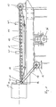
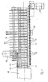
- the removal roller table according to FIGS. 1 and 2 consists of a plurality of rollers 10, 11 arranged in one plane.
- a heating device 12 is indicated, which may be an induction coil, for example.
- a further processing system e.g. a forging device or press
- the rollers 10 of the removal roller table are driven by a drive 13, a chain 14 and sprockets 15 located on each roller 10. Only the first roller 11 is independent of this drive 13. It is driven by a separate drive 16 via a chain 17 and its sprocket 18. The speed of the first roller 11 is approximately three times the speed of the other rollers 10.
- the first roller 11 has a cam profile.
- cam profiles can be seen in FIGS. 5 and 6.
- the role. 20 according to FIG. 5 is one that is derived from a cylindrical shape. It has on its circumference three flat surfaces 21 which are rotated relative to one another by 120 °. Between two of the flat surfaces 21 is welded onto the cylindrical surface 22 a round rod 23 running in the direction of the roll axis.
- the roller 24 according to FIG. 6 is one with an edge line 25 that is spiral in cross section.
- the inner and outer ends of the spiral edge line 25 are connected to one another by a flat transition surface 26.
- a cam 27 running along the roller axis is formed on the circumference of the roller 24.
- FIGS. 5 and 6 The direction of rotation of the rollers 20, 24 are shown in FIGS. 5 and 6 by an arrow 28. Furthermore, in both figures there is a block 29 above the roller 20, 24, the direction of movement of which is represented by an arrow 30.
- the block 29 located above it receives a powerful blow per revolution by the round rod 23 or the cam 27 and is lifted out of its horizontal position (shown in dashed lines). Since the subsequent block 31 tends to remain in its horizontal rest position, a force occurs on the adhesive surface 32 between the first block 29 and the subsequent block 31, through which, if the adhesive effect is not too strong, a gap 33 between the first block 29 and the subsequent block 31 is torn. Oxygen penetrates into the gap 33 and an oxide layer forms on the end faces of the blocks 29, 31, which prevents the blocks from being bonded or welded again.
- the removal roller table according to FIGS. 1 and 2 contains a comb bar 35 for separating (tipping) of reject blocks.
- the comb bar 35 is rotatably mounted about the shaft 36.
- the shaft 36 can be rotated by a drive 37.
- ends of the comb bar 35 located between the rollers 10 are raised. They also lift the blocks above, which slide laterally over the comb strip 35, which is inclined in this way.
- the rejection of reject blocks can also take place via a reject switch, as shown in FIG. 4.
- the reject switch is arranged at the end of the removal roller table. It consists of a slide 38 and a guide lever 40 which can be pivoted in the direction of the arrow 39. Depending on the position of the guide lever 40, the blocks slide straight ahead for further processing, or they are deflected sideways and fed to the reject bucket.
- the position of three light barriers 41 can be seen from FIG. 1, the distance from each other corresponding approximately to a block length.
- the light barriers 41 are reflection light scanners and combine both the transmitter and the receiver in one structural unit. Their output signal contains the information as to whether or not there is a block in the scanning area of the light barrier 41 or whether there is a block gap in the scanning area.
- a hold-down 42 is also shown, which is arranged approximately above the first roller 11 and limits the jumping up of the blocks.
- rollers 50, 51 are shown, in the surfaces of which there are circumferential grooves.
- the webs between two grooves of one roller engage in the grooves of the other roller.
- the axes of the two rollers 50, 51 can be guided relatively close to one another despite the relatively large outer diameter of the rollers.
- These rollers 50, 51 can be rollers with Act cam profile or rollers with a circular profile.
- the rollers 50, 51, which are interlocked in this way, are suitable for transporting short blocks.
- FIG. 7 shows the arrangement of three induction coils 45, 46, 47 connected in series.
- the coil axes of the three induction coils 45, 46, 47 are tilted against each other in the vertical direction.
Priority Applications (1)
| Application Number | Priority Date | Filing Date | Title |
|---|---|---|---|
| AT85110412T ATE37999T1 (de) | 1984-08-30 | 1985-08-20 | Entnahmerollgang einer schmiedeblockerwaermungsanlage. |
Applications Claiming Priority (2)
| Application Number | Priority Date | Filing Date | Title |
|---|---|---|---|
| DE3431819 | 1984-08-30 | ||
| DE3431819A DE3431819A1 (de) | 1984-08-30 | 1984-08-30 | Entnahmerollgang einer schmiedeblockerwaermungsanlage |
Publications (3)
| Publication Number | Publication Date |
|---|---|
| EP0173218A2 true EP0173218A2 (fr) | 1986-03-05 |
| EP0173218A3 EP0173218A3 (en) | 1986-10-22 |
| EP0173218B1 EP0173218B1 (fr) | 1988-10-19 |
Family
ID=6244223
Family Applications (1)
| Application Number | Title | Priority Date | Filing Date |
|---|---|---|---|
| EP85110412A Expired EP0173218B1 (fr) | 1984-08-30 | 1985-08-20 | Table à rouleaux de prise d'un installation d'échauffement de lingot de forge |
Country Status (3)
| Country | Link |
|---|---|
| EP (1) | EP0173218B1 (fr) |
| AT (1) | ATE37999T1 (fr) |
| DE (2) | DE3431819A1 (fr) |
Cited By (3)
| Publication number | Priority date | Publication date | Assignee | Title |
|---|---|---|---|---|
| ES2067365A2 (es) * | 1992-06-04 | 1995-03-16 | Forjas De Villalba S A | Sistema de aprovechamiento del calor de forja. |
| CN103466276A (zh) * | 2013-08-29 | 2013-12-25 | 苏州工业园区华福科技有限公司 | 拖板炉圆锭槽输送装置 |
| CN104493063A (zh) * | 2014-11-28 | 2015-04-08 | 芜湖银星汽车零部件有限公司 | 一种红打加工成型系统的输送加热装置 |
Citations (2)
| Publication number | Priority date | Publication date | Assignee | Title |
|---|---|---|---|---|
| DD122038A1 (fr) * | 1975-09-01 | 1976-09-12 | ||
| AT361759B (de) * | 1978-10-12 | 1981-03-25 | Wefoba | Verfahren und vorrichtung zur versorgung eines gesenkschmiedeautomaten |
-
1984
- 1984-08-30 DE DE3431819A patent/DE3431819A1/de active Granted
-
1985
- 1985-08-20 DE DE8585110412T patent/DE3565640D1/de not_active Expired
- 1985-08-20 AT AT85110412T patent/ATE37999T1/de not_active IP Right Cessation
- 1985-08-20 EP EP85110412A patent/EP0173218B1/fr not_active Expired
Patent Citations (2)
| Publication number | Priority date | Publication date | Assignee | Title |
|---|---|---|---|---|
| DD122038A1 (fr) * | 1975-09-01 | 1976-09-12 | ||
| AT361759B (de) * | 1978-10-12 | 1981-03-25 | Wefoba | Verfahren und vorrichtung zur versorgung eines gesenkschmiedeautomaten |
Cited By (5)
| Publication number | Priority date | Publication date | Assignee | Title |
|---|---|---|---|---|
| ES2067365A2 (es) * | 1992-06-04 | 1995-03-16 | Forjas De Villalba S A | Sistema de aprovechamiento del calor de forja. |
| CN103466276A (zh) * | 2013-08-29 | 2013-12-25 | 苏州工业园区华福科技有限公司 | 拖板炉圆锭槽输送装置 |
| CN103466276B (zh) * | 2013-08-29 | 2016-03-30 | 苏州工业园区华福科技有限公司 | 拖板炉圆锭槽输送装置 |
| CN104493063A (zh) * | 2014-11-28 | 2015-04-08 | 芜湖银星汽车零部件有限公司 | 一种红打加工成型系统的输送加热装置 |
| CN104493063B (zh) * | 2014-11-28 | 2017-01-18 | 芜湖银星汽车零部件有限公司 | 一种红打加工成型系统的输送加热装置 |
Also Published As
| Publication number | Publication date |
|---|---|
| ATE37999T1 (de) | 1988-11-15 |
| EP0173218A3 (en) | 1986-10-22 |
| DE3431819C2 (fr) | 1987-05-27 |
| EP0173218B1 (fr) | 1988-10-19 |
| DE3431819A1 (de) | 1986-03-13 |
| DE3565640D1 (en) | 1988-11-24 |
Similar Documents
| Publication | Publication Date | Title |
|---|---|---|
| DE3029458C2 (fr) | ||
| EP1251092B1 (fr) | Système à guider du matériau pour de machines de raccordement | |
| DE2608393C2 (de) | Förderanlage | |
| EP0453935B1 (fr) | Procédé et dispositif pour transporter des matériaux en feuilles superposées d'une table de réception vers une table d'alimentation dans une machine de coupe | |
| EP0780326A1 (fr) | Transporteur à accumulation avec au moins un moyen de transport sans fin | |
| DE1917062C3 (de) | Vorrichtung zum selbsttätigen Verteilen von Gegenständen | |
| EP1337450B1 (fr) | Aiguillage de transport destine a une voie de transport de materiau en forme de panneau, notamment une voie de transport de verre plat | |
| EP0173218B1 (fr) | Table à rouleaux de prise d'un installation d'échauffement de lingot de forge | |
| DE3201823A1 (de) | Verfahren und vorrichtung zur laermminderung beim quertransport rollfaehiger koerper | |
| DE2108798B2 (de) | Übergabe- und Zentriereinrichtung zu einem Aufzug | |
| EP0339488B1 (fr) | Dispositif pour individualiser des barres | |
| DE2952264C2 (fr) | ||
| WO2004050271A1 (fr) | Laminoir comprenant des moyens pour changer les cylindres | |
| DE19546887A1 (de) | Förderbahn für Paletten | |
| EP1026108B1 (fr) | Procédé et dispositif pour la formation d'empilement pour matériau de coupe | |
| EP0020287A1 (fr) | Dispositif pour le désempilage de couches empilées | |
| DE19953018B4 (de) | Einrichtung an kontinuierlich arbeitenden Bogenanlegern | |
| DE19712698C2 (de) | Anlage zum ausgerichteten Zuführen von Füllstreifen aus Dämmaterial im Zuge der Fertigung von Sandwichelementen | |
| DE1966372C3 (de) | Einrichtung zum Überführen von Lastenträgern für Schleppkreisförderer von einer ersten Antriebsschiene auf eine zweite. Ausscheidung aus: 1944345 | |
| DE3202443C2 (fr) | ||
| DE2064178B2 (de) | Querfoerderanlage fuer baumstaemme | |
| DE2263352C2 (de) | Hubbalkenförderer zum Vereinzeln und Positionieren von Walzband-Bunden | |
| DE2620908C2 (de) | Vorrichtung zum Palettieren von stehenden Fässern | |
| DE1962535B2 (de) | Zwischen zwei mit schwankender foerderleistung arbeitenden foerdermitteln angeordneter hubbalkenfoerderer | |
| DE2605564B2 (de) | Brennschneidanlage |
Legal Events
| Date | Code | Title | Description |
|---|---|---|---|
| PUAI | Public reference made under article 153(3) epc to a published international application that has entered the european phase |
Free format text: ORIGINAL CODE: 0009012 |
|
| AK | Designated contracting states |
Kind code of ref document: A2 Designated state(s): AT BE CH DE FR GB IT LI |
|
| PUAL | Search report despatched |
Free format text: ORIGINAL CODE: 0009013 |
|
| AK | Designated contracting states |
Kind code of ref document: A3 Designated state(s): AT BE CH DE FR GB IT LI |
|
| 17P | Request for examination filed |
Effective date: 19870422 |
|
| 17Q | First examination report despatched |
Effective date: 19880407 |
|
| RAP1 | Party data changed (applicant data changed or rights of an application transferred) |
Owner name: BBC BROWN BOVERI AKTIENGESELLSCHAFT |
|
| GRAA | (expected) grant |
Free format text: ORIGINAL CODE: 0009210 |
|
| AK | Designated contracting states |
Kind code of ref document: B1 Designated state(s): AT BE CH DE FR GB IT LI |
|
| REF | Corresponds to: |
Ref document number: 37999 Country of ref document: AT Date of ref document: 19881115 Kind code of ref document: T |
|
| RAP2 | Party data changed (patent owner data changed or rights of a patent transferred) |
Owner name: ASEA BROWN BOVERI AKTIENGESELLSCHAFT |
|
| GBT | Gb: translation of ep patent filed (gb section 77(6)(a)/1977) | ||
| REF | Corresponds to: |
Ref document number: 3565640 Country of ref document: DE Date of ref document: 19881124 |
|
| ITF | It: translation for a ep patent filed |
Owner name: DE DOMINICIS & MAYER S.R.L. |
|
| ET | Fr: translation filed | ||
| PLBE | No opposition filed within time limit |
Free format text: ORIGINAL CODE: 0009261 |
|
| STAA | Information on the status of an ep patent application or granted ep patent |
Free format text: STATUS: NO OPPOSITION FILED WITHIN TIME LIMIT |
|
| 26N | No opposition filed | ||
| BECN | Be: change of holder's name |
Effective date: 19881019 |
|
| PGFP | Annual fee paid to national office [announced via postgrant information from national office to epo] |
Ref country code: AT Payment date: 19900717 Year of fee payment: 6 |
|
| PGFP | Annual fee paid to national office [announced via postgrant information from national office to epo] |
Ref country code: CH Payment date: 19900726 Year of fee payment: 6 |
|
| PG25 | Lapsed in a contracting state [announced via postgrant information from national office to epo] |
Ref country code: AT Effective date: 19910820 |
|
| ITTA | It: last paid annual fee | ||
| PG25 | Lapsed in a contracting state [announced via postgrant information from national office to epo] |
Ref country code: LI Effective date: 19910831 Ref country code: CH Effective date: 19910831 |
|
| REG | Reference to a national code |
Ref country code: CH Ref legal event code: PL |
|
| PGFP | Annual fee paid to national office [announced via postgrant information from national office to epo] |
Ref country code: GB Payment date: 19920527 Year of fee payment: 8 |
|
| PGFP | Annual fee paid to national office [announced via postgrant information from national office to epo] |
Ref country code: FR Payment date: 19930708 Year of fee payment: 9 |
|
| PGFP | Annual fee paid to national office [announced via postgrant information from national office to epo] |
Ref country code: BE Payment date: 19930729 Year of fee payment: 9 |
|
| PG25 | Lapsed in a contracting state [announced via postgrant information from national office to epo] |
Ref country code: GB Effective date: 19930820 |
|
| GBPC | Gb: european patent ceased through non-payment of renewal fee |
Effective date: 19930820 |
|
| PG25 | Lapsed in a contracting state [announced via postgrant information from national office to epo] |
Ref country code: BE Effective date: 19940831 |
|
| BERE | Be: lapsed |
Owner name: ASEA BROWN BOVERI A.G. Effective date: 19940831 |
|
| PG25 | Lapsed in a contracting state [announced via postgrant information from national office to epo] |
Ref country code: FR Effective date: 19950428 |
|
| REG | Reference to a national code |
Ref country code: FR Ref legal event code: ST |
|
| PGFP | Annual fee paid to national office [announced via postgrant information from national office to epo] |
Ref country code: DE Payment date: 19960808 Year of fee payment: 12 |
|
| PG25 | Lapsed in a contracting state [announced via postgrant information from national office to epo] |
Ref country code: DE Free format text: LAPSE BECAUSE OF NON-PAYMENT OF DUE FEES Effective date: 19980501 |