EP0172592B1 - Method and printing device for the line-wise printing of a image composed of an assembly of image elements - Google Patents
Method and printing device for the line-wise printing of a image composed of an assembly of image elements Download PDFInfo
- Publication number
- EP0172592B1 EP0172592B1 EP85201234A EP85201234A EP0172592B1 EP 0172592 B1 EP0172592 B1 EP 0172592B1 EP 85201234 A EP85201234 A EP 85201234A EP 85201234 A EP85201234 A EP 85201234A EP 0172592 B1 EP0172592 B1 EP 0172592B1
- Authority
- EP
- European Patent Office
- Prior art keywords
- printing
- pixel
- printed
- line
- pixels
- Prior art date
- Legal status (The legal status is an assumption and is not a legal conclusion. Google has not performed a legal analysis and makes no representation as to the accuracy of the status listed.)
- Expired
Links
Images

Classifications
-
- B—PERFORMING OPERATIONS; TRANSPORTING
- B41—PRINTING; LINING MACHINES; TYPEWRITERS; STAMPS
- B41J—TYPEWRITERS; SELECTIVE PRINTING MECHANISMS, i.e. MECHANISMS PRINTING OTHERWISE THAN FROM A FORME; CORRECTION OF TYPOGRAPHICAL ERRORS
- B41J25/00—Actions or mechanisms not otherwise provided for
- B41J25/001—Mechanisms for bodily moving print heads or carriages parallel to the paper surface
- B41J25/006—Mechanisms for bodily moving print heads or carriages parallel to the paper surface for oscillating, e.g. page-width print heads provided with counter-balancing means or shock absorbers
-
- H—ELECTRICITY
- H04—ELECTRIC COMMUNICATION TECHNIQUE
- H04N—PICTORIAL COMMUNICATION, e.g. TELEVISION
- H04N1/00—Scanning, transmission or reproduction of documents or the like, e.g. facsimile transmission; Details thereof
- H04N1/04—Scanning arrangements, i.e. arrangements for the displacement of active reading or reproducing elements relative to the original or reproducing medium, or vice versa
- H04N1/19—Scanning arrangements, i.e. arrangements for the displacement of active reading or reproducing elements relative to the original or reproducing medium, or vice versa using multi-element arrays
- H04N1/191—Scanning arrangements, i.e. arrangements for the displacement of active reading or reproducing elements relative to the original or reproducing medium, or vice versa using multi-element arrays the array comprising a one-dimensional [1D] array
- H04N1/192—Simultaneously or substantially simultaneously scanning picture elements on one main scanning line
-
- H—ELECTRICITY
- H04—ELECTRIC COMMUNICATION TECHNIQUE
- H04N—PICTORIAL COMMUNICATION, e.g. TELEVISION
- H04N1/00—Scanning, transmission or reproduction of documents or the like, e.g. facsimile transmission; Details thereof
- H04N1/40—Picture signal circuits
- H04N1/40025—Circuits exciting or modulating particular heads for reproducing continuous tone value scales
- H04N1/40031—Circuits exciting or modulating particular heads for reproducing continuous tone value scales for a plurality of reproducing elements simultaneously
Definitions
- the invention relates to a method and a device for the linewise printing of an image composed of pixels in lines and columns.
- faster printing has been realized by providing a printing head with a plurality of single printing pixel elements spaced apart by linewise distances that are greater than the linewise pitch of pixels.
- the printing head then should be moved along the printing line, so that, in principle, for each line each pixel intended to be printed should be covered by at least one printing element.
- each of the printing elements may print a number of successive positions of each image line.
- Each pixel is assigned to one particular printing element and each pixel is covered by only one printing element for each particular color.
- the printing stroke corresponds to the distance between each pair of contiguous printing elements.
- the print control signal for each pixel corresponds to the intended pixel intensity.
- a disadvantage of the known method is that each position within a line is covered only by the same printing element.
- interference patterns arise in the printed image which disturb the optical density of the printed image.
- These interference patterns are characterized, for example, by a line pattern between successive strips of pixels which are printed by the same printing element, or by large differences in optical density which results in pattern of bands in the picture.
- the interference and/or band patterns arise as a result of geometrical and/or electrical inaccuracies in one or more printing elements of the printing head, and become all the more pronounced if a strip of successive pixels in successive image lines are printed by such a same printing element with an inaccuracy.
- this is realized by a method for printing an image composed of pixels in lines and columns by means of a printing head which comprises a plurality of single-pixel printing elements spaced apart by linewise distances that are greater than the linewise pitch of the pixels, in which method an actuation signal is generated for each pixel to be printed in a single colour and in which the said printing head is driven through temporally recurrent and spatially uniform linewise printing strokes that are larger than said linewise distances, so that in each pixel line printed there is at least one linewise strip formed of contiguous pixels which are each covered by at least two contiguous printing elements, allowing of selecting at choice which of said contiguous printing elements prints each a pixel or pixels in said strip so as to produce pixel lines in which a first pixel situated earlier in the line is printed by a printing element later in the succession, a second pixel situated later in the line is printed by a printing element earlier in the succession, and a third pixel still later in the line is again printed by said printing element
- the printing stroke is now greater than the distance between contiguous printing elements, the choice between two or more printing elements allows to distribute the effects of the inaccuracies.
- the first solution now is to give each line of pixels the same assignation. In case of a change of printing intensity between two printing elements, the subjective effect thereof could be more gradual.
- a second solution is to determine the assignation on a line by line basis. This also gives a geometrically blurring effect.
- a second aspect of the invention its object is realized in a method for printing an image composed of pixels in lines and columns by means of a printing head which comprises a plurality of single-pixel printing elements spaced apart by linewise distances that are greater than the linewise pitch of the pixels, in which method an actuation signal is generated for each pixel to be printed in a single colour and in which the said printing head is driven through temporally recurrent and spatially uniform linewise printing strokes that are larger than said linewise distances so that in each pixel line printed there is at least one linewise strip formed of contiguous pixels which are each covered by at least two contiguous printing elements, allowing of selecting at choice which of said contiguous printing elements each prints a pixel or pixels in said strip and which of said contiguous printing elements, together with another of said printing elements, will print twice a same pixel in said strip so as to produce pixel lines in which a first pixel situated earlier in the line is printed by a first printing element earlier in the succession, a second pixel situated later in the
- Figure 1a illustrates diagrammatically the relative movement of the printing head and the carrier
- Figure 1b illustrates the surface of a printing head which is brought into contact with a carrier
- Figure 2 shows an exemplary embodiment of a printing device
- Figure 3 shows a number of pixels in magnified format as printed by a conventional method
- Figures 4a to d incl
- Figure 4e shows a delta probability distribution pattern which is used in the first preferred embodiment of a method according to the invention
- Figure 4f depicts a manner of assigning weighting factors per position to the printing elements
- Figure 5 illustrates the operations carried out in a first preferred embodiment of a method according to the invention on the basis of a first flow chart
- Figures 6a to f incl. illustrate a second preferred embodiment of a method according to the invention
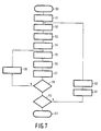
- Figure 7 illustrates the operations carried out in a second preferred embodiment of a method according to the invention on the basis of a second flow chart.
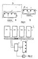
- FIG. 1a illustrates diagrammatically the relative movement of a printing head and the carrier in a preferred embodiment of a printing device in which a method according to the invention is used.
- This printing device embodies a printing head 2 which can be moved across a carrier, for example a paper 1.
- the paper moves in the direction of the arrow 5.
- the printing head 2 moves in the direction of the arrow 4 during the printing of an image line, and in the direction 4' during the return stroke of the printing head.
- the printing head embodies a number N(N ⁇ 2) of printing elements 6 which are disposed in a line, which line has substantially the same direction as the direction of motion of the printing head.
- the printing elements 6 are therefore placed perpendicular to the direction of movement of the paper.
- Figure 1b illustrates the surface of the printing head 2 which is brought into contact with the paper.
- the printing element 6, which are dot-shaped or line-shaped, are placed at a mutual distance dp from each other which is termed the "printing element pitch".
- the printing element pitch is larger than the distance between two successive pixels in the same image line.
- Each printing element is connected to a control line for the transmission of control signals for the activation of the printing element.
- the various control lines are assembled in a control bus 3.
- a Print stroke the printing head traverses a width b across the paper and prints an image line on the paper.
- the invention will be described by reference to a preferred embodiment in which the printing element 6 take the form of thermal printing elements.
- the printing device will therefore be described as a "thermal printing device".
- the printing elements embody a resistance element and a control signal takes the form of a current pulse. Under the influence of such a current pulse a printing element is heated up. This heat is transferred to the paper.
- the paper has been treated, for example, with a chemical substance which, as a result of heat being supplied, locally undergoes a change or, for example, a layer of wax paper is introduced between the printing head and the carrier.
- the use of colored wax paper makes color printing possible. It will be clear that other printing elements such as, for example, printing needles or ink-jet printers, can also be used in the application ofthe invention.
- each line is built up of an assembly of pixels which are printed by the dot-shaped or line-shaped printing elements.
- the printing elements are activated under the control of control signals and in each case between two successive series of control signals the printing head is moved to a small extent in the direction of the arrow 4.
- the printing stroke is substantially equal to the printing element pitch.
- FIG. 2 shows an example of a device for the printing of information.
- This device embodies a CPU 10, a read memory 11, for example a ROM, and a read/write memory 17, for example a RAM, and also an input/output interface 12, which are interconnected by means of a system bus 14 for the transmission of data and addresses.
- a system bus 14 for the transmission of data and addresses.
- a printing head control element 13 To the system bus 14 there is further connected a printing head control element 13, which in its turn is connected via the control bus 3 to the printing head 2.
- the printing head control element 13 is further connected to a motor 16 which is responsible for the movement of the printing head.
- the input/output interface 12 has a number of connection lines 15 over which the information to be printed (for example, originating from a teletext receiver) is supplied.
- the read memory 11 there are stored, inter alia, programs for the control of the printing head. These programs are performed in the known manner under the control of the CPU. Under control of the CPU and with the help of a program the information supplied via the input/output interface 12 is translated into control signals which are fed to the printing head control element via the system bus 14. Each control signal contains an intensity which is matched to the pixel print value of the pixel to be printed, and is then converted at this point into energy for the activation of a printing element. In the case of a thermal printer this energy takes the form of electrical current pulses. The duration and/or the current strength of these electrical current pulses is variable as a function of the pixel print value of the pixel to be printed. As a result of this the quantity of heat transferred to the paper varies.
- Figure 3 shows in enlarged format a number of image elements such as printed by a method in which the print stroke is equal to the element pitch. It is assumed that the printing head embodies four printing elements which are indicated by the capital letters A, B, C and D.
- a full printing stroke is made up of a number of substrokes (in this example, 5), and each printing element prints a pixel on the paper during such a substroke, which pixels lie on the same line. During one printing stroke a number of pixels are therefore printed.
- four successive printing strokes are illustrated.
- the assembly of pixels a, or respectively b, c, d are printed by the printing elements A, or respectively B, C, D.
- Figure 3 shows clearly the problem which occurs if dot-shaped pixels are printed with a printing head of this type.
- a image contains a large number of pixels in which each pixel contains a number of image half tones or color intensities.
- the pixel printed by a printing element does not have a pure geometrical round or square shape.
- the uniform shape of the geometrical pattern is often disturbed as depicted in the pixel assembly b, c and d.
- the invention now offers a number of methods of reducing the effect of the abovenamed faults in a printed image.
- the methods have in common that the printing stroke is greater than the element pitch.
- pixels are now covered by more than one printing element within the same line. If therefore in at least one strip of pixels which extends transversely to the printing line direction and which for each image line contains several pixels which are each covered by m (2 ⁇ ⁇ m ⁇ ⁇ N) printing elements, the possibility is created of causing that pixel to be printed by one or more of these m printing elements.
- the methods according to the invention are in the main to be distinguished in four embodiments, viz.:
- Figures 4a to e incl. illustrate exemplary embodiments of the methods 2, 3 and 4.
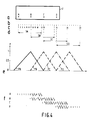
- Figure 4a shows a per se known printing head 2 of a thermal printing device.
- Figure 4b shows a row of 30 pixels which represent the 30 positions covered by the printing head 2 and
- Figure 4c gives numbers to the successive positions of the pixels in Figure 4b.
- Figure 4d illustrates the distance which is covered in this exemplary embodiment by the various printing elements during one complete printing stroke. From Figure 4 it can clearly be deduced that in this exemplary embodiment of a method according to the invention the printing stroke now comprises substantially twice the length of the printing element pitch. In relation to the usual printing stroke this therefore signifies a printing stroke which is substantially twice as large.
- the method according to the invention is not limited to a printing stroke which is substantially equal to twice the printing element pitch.
- the printing stroke may also describe a length of more than twice the printing element pitch.
- the printing stroke may also be only a fraction larger than the printing element pitch in a manner such that there is only a strip of two or more pixels which are covered by several printing elements.
- the end positions 1 to 6 incl. and 25 to 30 incl. are only serviced by one printing element because of technical limitations.
- a first control signal which, depending on the pixel print value, represents a quantity of energy or the time within which energy is supplied to a printing element (the quantity of energy which is supplied per unit time is then fixed in this latter instance).
- the quantity of energy (or time) stored in that first control signal should be distributed over one or more of the printing elements which cover the relevant position.
- the method according to the invention provides several options for this purpose, such as the determination per position of weighting factors for each printing element or for p of the m printing elements which cover the position, or the establishment of a fixed distribution pattern in which a series of positions to be printed are assigned to each printing element, which series of positions is then distributed over the path described by the relevant printing element.
- a boundary condition for the determination of that weighting factor (P ij ) is that the total sum of the weighting factors summed over all (p) printing elements (i) which cover a certain position (j) (where 2 ⁇ ⁇ p ⁇ ⁇ m, and m is the number of printing elements which cover the position j) must be a constant c for that position.
- the constant has a value 1 ⁇ ⁇ c ⁇ ⁇ 1.5 because the given pixel must of course be printed undiminished in that position.
- the weighting factors are predetermined or are, for example, determined by means of a probability distribution.
- a common probability distribution is, for example, a delta probability distribution or a sinusoidal probability distribution.
- Figure 4e shows a delta probability distribution for the positions 1 to 30 incl.
- PA represents the weighting factors for the positions 1 to 12 incl. for printing with printing element A.
- PB, PC and PD represent the weighting factors for the printing of the respective positions 7 to 18 incl., 13 to 24 incl. and 19 to 30 incl. by the respective printing elements B, C and D. From this Figure 4e it can be deduced that printing element A prints position 7.
- Position 10 is printed both by printing element A and by printing element B. For this position 10 the energy stored in the first control signal for this position is distributed equally over the two printing elements A and B.
- weighting factor which represents a portion of the energy is assigned per position to the printing elements which cover that position.
- a weighting factor of 2/3 is assigned to the printing element B and a weighting factor 1/3 is assigned to the printing element C.
- 2/3 of the energy of the first control signal is then fed to the printing element B and 1/3 of the energy to the printing element C.
- the sum of a series of weighting factors per position is in this case chosen as equal to 1.
- this sum may also be somewhat larger than 1, for example, weighting factors of 0.6 and 0.5 for one position are also permissible.
- the total energy supplied to all the printing elements which service that position may be somewhat larger than the energy from the first control signal because allowance is made, for example, for heating-up effects in the various printing elements.
- the series of weighting factors is, for example, stored in the memory of the printing device, which memory then fulfils the function of a distribution pattern generator.
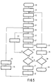
- Figure 5 shows the operations carried out in a first preferred embodiment of a method according to the invention on the basis of a flow chart.
- this first preferred embodiment use is made of a probability distribution for the generation of the weighting factors. It is assumed that printing is only done in a single color (for example black). The printing of several colors will be dealt with later.
- the printing head is controlled by a CPU.
- a suitable program for this purpose is called up from the memory and started (20) under the control of the CPU once a user or a data processing unit has given the necessary instruction.
- a line counter which counts the number of lines to be printed, is set to a starting position, for example the "zero" position.
- a weighting factor is then determined on the basis of a probability distribution for each position situated within the line to be printed.
- the weighting factor is determined, for example, on the basis of a delta distribution such as depicted in Figure 4e.
- These weighting factors are generated by a distribution code generator which is part of the CPU and the read memory.
- the generated weighting factors for each position are stored in the read write memory.
- an index flag is set to the "zero" postion (23). This index flag serves to indicate within which position ranges the printing head is located.
- the index flag has two positions, viz. the position "0" for the first half of the printing stroke and the position "1" for the second half of the printing stroke.
- the information to be printed in the first line is called up (24) (for example, via the input/ output interface or from the memory), and on the basis of the information to be printed there is called up a series of first control signals (I i ) which represent a quantity of energy for the activation of a printing element for each of the positions (i) to be printed in the line, or the time within which the activation must take place.
- the series of first control signals is determined under the control of the CPU.
- This series of first control signals is stored in a memory location allocated for the purpose, termed a "Printing table". Then a position counter is set to the starting position (25), for example the "0" position. This position counter counts the number of positions in one position of the pitch flat (for example, 6 as illustrated in Figure 4b). Then an operation is carried out (26) in which the weighting factor which is stored in the memory for the positions and a certain printing element is applied to the first control signal for these positions. This operation will be explained by reference to the example given in Figure 4. When the position counter is in the starting position, printing element A covers position 1, printing element B covers position 7 and printing element C or D covers position 13 or 19 respectively.
- the first control signals I1, I7, I13 and I19 for the positions 1, 7, 13 and 19 are now called up from the printing table.
- the weighting factors for the various positions and the various printing elements are P A1 , P B7 , P C13 and P D19 , and these values are also called up from the memory.
- the CPU now performs the following operations.
- P A1 o I1 S A1
- P B7 o I7 S B7
- P C13 o I13 S C13 P D19 o
- I19 S D19 (where o stands for "acts on”; this may be a logic "AND” operation or a multiplication).
- the result of this operation produces a second control signal S j,i for the relevant position.
- the second control signal then represents the quantity of energy which is supplied to a certain printing element (i) which covers the position (i) (or the length of time within which energy is supplied to the printing element).
- the set of second control signals is stored in a buffer. Subsequently (27) the printing elements are activated under the control of their respective second control signals for printing information on the paper.
- the setting of the position counter is then changed by one unit (28) (increased or reduced depending on the starting position of the position counter) and a check is made (29) as to whether all the positions to be printed in one setting of the index flag have been covered, i.e. whether the position counter has reached its final setting.
- step 27 the printing elements are activated under the control of the second control signals S A2 , S B8 , S C14 and S D20 .
- the steps 26, 27, 28, 29 and 33 are repeated until the position counter has reached its final position and all the positions for the setting "0" of the index flag have consequently been covered by the printing head.
- step 29 a check is made as to the setting the index flag is in (30). If it is the "0" position, step 31 is proceeded to, and if it is the"1" position, then step 38 is proceeded to.
- step 31 a new set of weighting factors is determined for the positions which are covered in a new position of the index flag. This is necessary because positions are now covered which were already covered by another printing element in the previous setting of the index flag. For the example given in Figure 4, in which a delta probability distribution is used and the index flag has only two settings, this new probability factor can easily be determined from the relationship (z - P j, i ), where z represents a constant value which is set equal to 1 for the present example. In certain circumstances z may also be chosen as larger than 1 in order to make a correction for certain switching-on effects such as, for example, heating-up effects.
- a shift operation (32) is carried out on the first control signals in the printing table and on the weighting factor in the memory.
- Printing element A now covers the positions 7 to 12 incl., printing element B - the positions 13 to 18 incl., printing element C or D the positions 19 to 24 incl. or 25 to 30 incl. respectively.
- the shift operation is actually a modulo 6 shift operation so that, for example, I7 is now denoted as I1 and P7 is denoted as P1.
- step 25 where the position counter is again set to a starting position and to step 26, where the operations described for it are performed again.
- the printing head is displaced to an adjacent position and the index flag is set to a new position (35), in this example the position "1".
- the program is then resumed from step 25.
- the various subsequent steps are repeated for the positions to be printed in position "1" of the index flag.
- step 30 where a check is made as to whether the index flag is in the position "0", the answer will now be negative and this being so, step 38 will be proceeded to at this point. In this step 38 a check is made as to whether all the lines to be printed have already been covered.
- step 24 only that information which re-lates to the color to be printed is called up, and only first control signals are determined for the relevant color. If, for example, a colored video image is being printed, the recognition of the colour to be printed can be derived from the RGB signals.
- the program as depicted by the flow chart in Figure 6 is then executed for each of the primary colours RGB.
- FIG. 6 shows the 24 different positions which are covered during one printing stroke.
- the printing head moves over a distance which is substantially equal to three times the element pitch (this latter point therefore implies that the index flag has three positions).
- the positions which are covered by the various printing elements during a printing stroke are represented by means of line segments in Figure 6e.
- the letter associated with the line segment indicates the printing element.
- the positions 1 to 9 incl. are covered by printing element A.
- Figure 6c, 6d and 6e show a first, second and third preferred embodiment respectively of such a fixed distribution pattern.
- the letters underneath the various positions as shown in Figure 6b indicate which printing element of the printing head services the various positions.
- the successive positions 7, 8 and 9, for example are in each case serviced by a different printing element, viz. C, A and B. This also applies to the positions 10 to 18 incl.
- Figure 6e shows a distribution pattern in which the printing elements are energised alternately within a strip. Because successive positions are now serviced by different printing elements, effects due to geometric inaccuracies in a printing element are averaged out and the printing elements are allowed some time to cool down between successive activations.
- the distribution pattern stipulating which printing element will service a position during the printing is, for example, stored in the memory of the printing device, which memory acts as a selection unit for the selection of one of m printing elements.
- a distribution pattern is called up from the memory, for example the distribution pattern given in Figure 6d.
- a position counter is set to a starting position, for example the "0" position. This position counter counts the number of positions within a line, for example 24 as shown in Figure 6b.
- an operation (55) is carried out in which second control signals for the activation of the printing elements are determined.
- the second control signals for the starting position of the position counter are:
- the second control signals ensure that all the allocated printing elements are energised at the respective positions. For these positions the intensity of the second control signal is therefore equal to that of the first control signal.
- the printing elements are activated (56) under the control of the second control signals for printing the information.
- the elements A and B are activated since the other second control signals S7, S10, S13, S16 have a value of 0. This is because the positions 7, 10, 13, 16 are not being selected by the printing elements which are located in these positions at this instant (for example, position 7 is serviced by printing element A which is now in position 1).
- the setting of the position coun-ter is increased by 1, and then (58) a check is made as to whether all the positions in the line have been covered. If this is not the case (N) the printing head is displaced (59) and the printing program is repeated from step 55 for the next positions to be covered. Again referring to the example, these are the positions 2, 5, 8, 11, 14 and 17.
- the second control signals are now:
- step 58 all the positions of the line to be printed have been covered. If all the positions have been covered (Y ), a check is made (60) as to whether all the lines to be printed have been covered (position of line counter). If all the lines to be printed have been covered (Y ), the printing program is terminated (63). If not (N), a return stroke impulse is transmitted to the printing head (61) which sets it to the starting position and the paper is displaced. Then (62) the setting of the line counter is changed by 1 (increased or decreased) and the printing program is repeated from step 21 for a following line to be printed.
- Such a distribution pattern for assigning m printing elements to each position which is covered by m printing elements is either predetermined and stored in a memory or generated by means of a distribution pattern generator (composed of the CPU and the memory). Preferably, this distribution pattern is the same for every image line, which simplifies the control of the printing process.
- the distribution pattern genera-tor operates, for example, by making use of a probability value distribution.
- n x printing element pitch An upper limit for the value of n is determined, for example, by choosing n as not larger than the number of positions within one element pitch.
- a favorable solution for a printing head with six printing elements and a printing element pitch of 4 is, for example, a printing stroke of 4 x the printing element pitch.
Landscapes
- Engineering & Computer Science (AREA)
- Multimedia (AREA)
- Signal Processing (AREA)
- Electronic Switches (AREA)
Description
- The invention relates to a method and a device for the linewise printing of an image composed of pixels in lines and columns. In particular, faster printing has been realized by providing a printing head with a plurality of single printing pixel elements spaced apart by linewise distances that are greater than the linewise pitch of pixels. The printing head then should be moved along the printing line, so that, in principle, for each line each pixel intended to be printed should be covered by at least one printing element.
- Such a method is known from British Patent Application GB-A-2,025,725. In each line each of the printing elements may print a number of successive positions of each image line. Each pixel is assigned to one particular printing element and each pixel is covered by only one printing element for each particular color. The printing stroke corresponds to the distance between each pair of contiguous printing elements. The print control signal for each pixel corresponds to the intended pixel intensity.
- A disadvantage of the known method is that each position within a line is covered only by the same printing element. As a result of this, in the linewise printing of an image, in particular a graphic image, or in the printing of half tones, interference patterns arise in the printed image which disturb the optical density of the printed image. These interference patterns are characterized, for example, by a line pattern between successive strips of pixels which are printed by the same printing element, or by large differences in optical density which results in pattern of bands in the picture. The interference and/or band patterns arise as a result of geometrical and/or electrical inaccuracies in one or more printing elements of the printing head, and become all the more pronounced if a strip of successive pixels in successive image lines are printed by such a same printing element with an inaccuracy.
- Among other things, it is an object of the invention to provide a printing method, wherein the subjective effect of the mentioned inaccuracies would not present themselves as vertical bands, but would be made rather more unobtrusive.
- According a first aspect of the invention, this is realized by a method for printing an image composed of pixels in lines and columns by means of a printing head which comprises a plurality of single-pixel printing elements spaced apart by linewise distances that are greater than the linewise pitch of the pixels, in which method an actuation signal is generated for each pixel to be printed in a single colour and in which the said printing head is driven through temporally recurrent and spatially uniform linewise printing strokes that are larger than said linewise distances, so that in each pixel line printed there is at least one linewise strip formed of contiguous pixels which are each covered by at least two contiguous printing elements, allowing of selecting at choice which of said contiguous printing elements prints each a pixel or pixels in said strip so as to produce pixel lines in which a first pixel situated earlier in the line is printed by a printing element later in the succession, a second pixel situated later in the line is printed by a printing element earlier in the succession, and a third pixel still later in the line is again printed by said printing element later in the succession.
- Because the printing stroke is now greater than the distance between contiguous printing elements, the choice between two or more printing elements allows to distribute the effects of the inaccuracies. The first solution now is to give each line of pixels the same assignation. In case of a change of printing intensity between two printing elements, the subjective effect thereof could be more gradual. A second solution is to determine the assignation on a line by line basis. This also gives a geometrically blurring effect.
- According to a second aspect of the invention, its object is realized in a method for printing an image composed of pixels in lines and columns by means of a printing head which comprises a plurality of single-pixel printing elements spaced apart by linewise distances that are greater than the linewise pitch of the pixels, in which method an actuation signal is generated for each pixel to be printed in a single colour and in which the said printing head is driven through temporally recurrent and spatially uniform linewise printing strokes that are larger than said linewise distances so that in each pixel line printed there is at least one linewise strip formed of contiguous pixels which are each covered by at least two contiguous printing elements, allowing of selecting at choice which of said contiguous printing elements each prints a pixel or pixels in said strip and which of said contiguous printing elements, together with another of said printing elements, will print twice a same pixel in said strip so as to produce pixel lines in which a first pixel situated earlier in the line is printed by a first printing element earlier in the succession, a second pixel situated later in the line is printed in part by said first printing element and in part by a second printing element later in the succession, based upon a fractional assignation of the print energy to said two printing elements, so that the summed printing intensities are equal to an intended pixel intensity level, and a third pixel situated still later in the line is printed by said second printing element, exclusively. Also here, the choice may be made between a fixed assignation pattern and a variable assignation pattern.
- Devices for executing the method delineated above are claimed in
independent claims - The invention will be explained in further detail with reference to the drawings in which:
Figure 1a illustrates diagrammatically the relative movement of the printing head and the carrier;
Figure 1b illustrates the surface of a printing head which is brought into contact with a carrier;
Figure 2 shows an exemplary embodiment of a printing device;
Figure 3 shows a number of pixels in magnified format as printed by a conventional method;
Figures 4a to d incl. illustrate a first preferred embodiment of a method according to the invention;
Figure 4e shows a delta probability distribution pattern which is used in the first preferred embodiment of a method according to the invention;
Figure 4f depicts a manner of assigning weighting factors per position to the printing elements;
Figure 5 illustrates the operations carried out in a first preferred embodiment of a method according to the invention on the basis of a first flow chart;
Figures 6a to f incl. illustrate a second preferred embodiment of a method according to the invention;
Figure 7 illustrates the operations carried out in a second preferred embodiment of a method according to the invention on the basis of a second flow chart. - Figure 1a illustrates diagrammatically the relative movement of a printing head and the carrier in a preferred embodiment of a printing device in which a method according to the invention is used. This printing device embodies a
printing head 2 which can be moved across a carrier, for example apaper 1. The paper moves in the direction of thearrow 5. Theprinting head 2 moves in the direction of thearrow 4 during the printing of an image line, and in the direction 4' during the return stroke of the printing head. The printing head embodies a number N(N ≧ 2) ofprinting elements 6 which are disposed in a line, which line has substantially the same direction as the direction of motion of the printing head. Theprinting elements 6 are therefore placed perpendicular to the direction of movement of the paper. Figure 1b illustrates the surface of theprinting head 2 which is brought into contact with the paper. Theprinting element 6, which are dot-shaped or line-shaped, are placed at a mutual distance dp from each other which is termed the "printing element pitch". The printing element pitch is larger than the distance between two successive pixels in the same image line. Each printing element is connected to a control line for the transmission of control signals for the activation of the printing element. The various control lines are assembled in acontrol bus 3. During a full movement, termed a "Printing stroke", the printing head traverses a width b across the paper and prints an image line on the paper. - The invention will be described by reference to a preferred embodiment in which the
printing element 6 take the form of thermal printing elements. The printing device will therefore be described as a "thermal printing device". The printing elements embody a resistance element and a control signal takes the form of a current pulse. Under the influence of such a current pulse a printing element is heated up. This heat is transferred to the paper. The paper has been treated, for example, with a chemical substance which, as a result of heat being supplied, locally undergoes a change or, for example, a layer of wax paper is introduced between the printing head and the carrier. The use of colored wax paper makes color printing possible. It will be clear that other printing elements such as, for example, printing needles or ink-jet printers, can also be used in the application ofthe invention. - An image is printed line-wise on the paper and each line is built up of an assembly of pixels which are printed by the dot-shaped or line-shaped printing elements. The printing elements are activated under the control of control signals and in each case between two successive series of control signals the printing head is moved to a small extent in the direction of the
arrow 4. In known printing devices the printing stroke is substantially equal to the printing element pitch. - Figure 2 shows an example of a device for the printing of information. This device embodies a
CPU 10, a read memory 11, for example a ROM, and a read/writememory 17, for example a RAM, and also an input/output interface 12, which are interconnected by means of asystem bus 14 for the transmission of data and addresses. To thesystem bus 14 there is further connected a printinghead control element 13, which in its turn is connected via thecontrol bus 3 to theprinting head 2. The printinghead control element 13 is further connected to a motor 16 which is responsible for the movement of the printing head. The input/output interface 12 has a number ofconnection lines 15 over which the information to be printed (for example, originating from a teletext receiver) is supplied. In the read memory 11 there are stored, inter alia, programs for the control of the printing head. These programs are performed in the known manner under the control of the CPU. Under control of the CPU and with the help of a program the information supplied via the input/output interface 12 is translated into control signals which are fed to the printing head control element via thesystem bus 14. Each control signal contains an intensity which is matched to the pixel print value of the pixel to be printed, and is then converted at this point into energy for the activation of a printing element. In the case of a thermal printer this energy takes the form of electrical current pulses. The duration and/or the current strength of these electrical current pulses is variable as a function of the pixel print value of the pixel to be printed. As a result of this the quantity of heat transferred to the paper varies. - Figure 3 shows in enlarged format a number of image elements such as printed by a method in which the print stroke is equal to the element pitch. It is assumed that the printing head embodies four printing elements which are indicated by the capital letters A, B, C and D. A full printing stroke is made up of a number of substrokes (in this example, 5), and each printing element prints a pixel on the paper during such a substroke, which pixels lie on the same line. During one printing stroke a number of pixels are therefore printed. In the initial Figure 3 four successive printing strokes are illustrated. The assembly of pixels a, or respectively b, c, d are printed by the printing elements A, or respectively B, C, D. Figure 3 shows clearly the problem which occurs if dot-shaped pixels are printed with a printing head of this type. A image contains a large number of pixels in which each pixel contains a number of image half tones or color intensities. As a result of geometrical and/or electrical inaccuracies in the various printing elements of the printing head (the geometrical shape and or the resistance values can vary for each printing element) the pixel printed by a printing element does not have a pure geometrical round or square shape. The uniform shape of the geometrical pattern is often disturbed as depicted in the pixel assembly b, c and d. This has the result that the optical density within an assembly of pixels is often disturbed, as a result of which, on the one hand, within the assembly of pixels small unprinted spots occur, but a clear vertical band structure is also produced in the plate. Each assembly of pixels which is printed by the same printing element forms, as it were, a separate band in the plate. Furthermore gaps also occur between the successive bands as a result of inaccurate positioning. Viewed over the whole image these gaps then form an annoying pattern of successive vertical lines which, certainly in the case of a color plate, disturb the image.
- The invention now offers a number of methods of reducing the effect of the abovenamed faults in a printed image. The methods have in common that the printing stroke is greater than the element pitch. As a result of this, pixels are now covered by more than one printing element within the same line. If therefore in at least one strip of pixels which extends transversely to the printing line direction and which for each image line contains several pixels which are each covered by m (2 ≦αµρ¨ m ≦αµρ¨ N) printing elements, the possibility is created of causing that pixel to be printed by one or more of these m printing elements.
- The methods according to the invention are in the main to be distinguished in four embodiments, viz.:
- 1) Allocation of one of the said m printing elements according to a fixed distribution pattern to each pixel in such a strip, printing of each of the pixels by means of the energising of each of the allocated printing elements under control of the control signal generated for that pixel.
- 2) Generation of a distribution pattern for each picture line to be printed in such a strip, according to which distribution pattern one of the said m printing elements is allocated to each pixel in any strip, and printing of each of the pixels by means of the energising of each of the allocated printing elements under control of the control signal generated for that pixel.
- 3) Allocation of p (2 ≦αµρ¨ p ≦αµρ¨ m) of the said m printing elements according to a predetermined distribution pattern to each pixel in such a strip, and printing of each of the pixels with a portion of the intensity of the pixel print value for that point, which portion is determined either according to a fixed distribution code or according to a distribution code generated for that image line.
- 4) Generation of a distribution pattern for each image line to be printed from such a strip, according to which distribution pattern p (2 ≦αµρ¨ p ≦αµρ¨ m) of the printing elements are allocated to each of the pixels in such a strip, and printing of each of the pixels with a portion of the intensity of the pixel print value for that point, which portion is determined according to a distribution code generated for the relevant picture line.
- These various methods will now be described in more detail. The Figures 4a to e incl. illustrate exemplary embodiments of the
methods printing head 2 of a thermal printing device. Figure 4b shows a row of 30 pixels which represent the 30 positions covered by theprinting head 2 and Figure 4c gives numbers to the successive positions of the pixels in Figure 4b. Figure 4d illustrates the distance which is covered in this exemplary embodiment by the various printing elements during one complete printing stroke. From Figure 4 it can clearly be deduced that in this exemplary embodiment of a method according to the invention the printing stroke now comprises substantially twice the length of the printing element pitch. In relation to the usual printing stroke this therefore signifies a printing stroke which is substantially twice as large. With printing element A it is now possible to print at thepositions 1 to 12 incl., while with the printing element B thepositions 7 to 18 incl. can be printed. The printing element C or respectively D can print thepositions 13 to 20 incl. or respectively 19 to 30 incl. This therefore implies that, for example, thepositions 7 to 12 can be printed both by printing element A and by printing element B. As a result of this, the assemblies of pixels which are covered by the different printing elements will overlap each other, as a result of which the strip pattern described above is suppressed and as a result of which optical variations in density are smoothed out. - It will be clear that the method according to the invention is not limited to a printing stroke which is substantially equal to twice the printing element pitch. The printing stroke may also describe a length of more than twice the printing element pitch. But the printing stroke may also be only a fraction larger than the printing element pitch in a manner such that there is only a strip of two or more pixels which are covered by several printing elements. In this exemplary embodiment the
end positions 1 to 6 incl. and 25 to 30 incl. are only serviced by one printing element because of technical limitations. - For each of the pixels to be printed there is generated a first control signal which, depending on the pixel print value, represents a quantity of energy or the time within which energy is supplied to a printing element (the quantity of energy which is supplied per unit time is then fixed in this latter instance). In view of the fact that several printing elements are now covered according to the invention, the quantity of energy (or time) stored in that first control signal should be distributed over one or more of the printing elements which cover the relevant position. The method according to the invention provides several options for this purpose, such as the determination per position of weighting factors for each printing element or for p of the m printing elements which cover the position, or the establishment of a fixed distribution pattern in which a series of positions to be printed are assigned to each printing element, which series of positions is then distributed over the path described by the relevant printing element.
- A boundary condition for the determination of that weighting factor (Pij) is that the total sum of the weighting factors summed over all (p) printing elements (i) which cover a certain position (j)

must be a constant c for that position. The constant has avalue 1 ≦αµρ¨ c ≦αµρ¨ 1.5 because the given pixel must of course be printed undiminished in that position. The weighting factors are predetermined or are, for example, determined by means of a probability distribution. A common probability distribution is, for example, a delta probability distribution or a sinusoidal probability distribution. Figure 4e shows a delta probability distribution for thepositions 1 to 30 incl. for the printing elements A, B, C and D. PA represents the weighting factors for thepositions 1 to 12 incl. for printing with printing element A. PB, PC and PD represent the weighting factors for the printing of therespective positions 7 to 18 incl., 13 to 24 incl. and 19 to 30 incl. by the respective printing elements B, C and D. From this Figure 4e it can be deduced that printing elementA prints position 7.Position 10 is printed both by printing element A and by printing element B. For thisposition 10 the energy stored in the first control signal for this position is distributed equally over the two printing elements A and B. Becauseposition 10 is now covered by two printing elements the chance that in this position a fault in the optical density occurs as a result of an inaccuracy in a printing element (for example, printing element B) is considerably reduced. Furthermore, for each line of the image to be printed a new set of weighting factors is generated. As a result of this the optical fault viewed over all the lines of the image will then be further reduced. - In an analogous manner to that in which weighting factors are determined for the distribution of the energy, it is also possible to determine a distribution pattern for the selection of p of m printing elements.
- Making use of a probability distribution is, of course, only one way of generating weighting factors. Another way of assigning weighting factors is depicted in Figure 4f. In this case a weighting factor which represents a portion of the energy is assigned per position to the printing elements which cover that position. Thus, for example, for
position 14, which is served both by printing element B and printing element C, a weighting factor of 2/3 is assigned to the printing element B and aweighting factor 1/3 is assigned to the printing element C. In printing theposition - The series of weighting factors is, for example, stored in the memory of the printing device, which memory then fulfils the function of a distribution pattern generator.
- Figure 5 shows the operations carried out in a first preferred embodiment of a method according to the invention on the basis of a flow chart. In this first preferred embodiment use is made of a probability distribution for the generation of the weighting factors. It is assumed that printing is only done in a single color (for example black). The printing of several colors will be dealt with later. As already noted in the description of Figure 2, the printing head is controlled by a CPU. In order to print a image which is composed of dot-shaped or line-shaped image elements, a suitable program for this purpose is called up from the memory and started (20) under the control of the CPU once a user or a data processing unit has given the necessary instruction. At the start of the execution of the program a line counter, which counts the number of lines to be printed, is set to a starting position, for example the "zero" position. A weighting factor is then determined on the basis of a probability distribution for each position situated within the line to be printed. The weighting factor is determined, for example, on the basis of a delta distribution such as depicted in Figure 4e. These weighting factors are generated by a distribution code generator which is part of the CPU and the read memory. The generated weighting factors for each position are stored in the read write memory. After the generation of the weighting factors an index flag is set to the "zero" postion (23). This index flag serves to indicate within which position ranges the printing head is located. Thus, in the exemplary embodiment in which the printing stroke extends over substantially twice the length of the printing element pitch, the index flag has two positions, viz. the position "0" for the first half of the printing stroke and the position "1" for the second half of the printing stroke. Then the information to be printed in the first line is called up (24) (for example, via the input/ output interface or from the memory), and on the basis of the information to be printed there is called up a series of first control signals (Ii) which represent a quantity of energy for the activation of a printing element for each of the positions (i) to be printed in the line, or the time within which the activation must take place. The series of first control signals is determined under the control of the CPU. This series of first control signals is stored in a memory location allocated for the purpose, termed a "Printing table". Then a position counter is set to the starting position (25), for example the "0" position. This position counter counts the number of positions in one position of the pitch flat (for example, 6 as illustrated in Figure 4b). Then an operation is carried out (26) in which the weighting factor which is stored in the memory for the positions and a certain printing element is applied to the first control signal for these positions. This operation will be explained by reference to the example given in Figure 4. When the position counter is in the starting position, printing element A covers
position 1, printing element B coversposition 7 and printing element C or D coversposition positions
PA1 o I₁ = SA1
PB7 o I₇ = SB7
PC13o I₁₃ = SC13
PD19o 90 I₁₉ = SD19
(where o stands for "acts on"; this may be a logic "AND" operation or a multiplication). The result of this operation produces a second control signal Sj,i for the relevant position. The second control signal then represents the quantity of energy which is supplied to a certain printing element (i) which covers the position (i) (or the length of time within which energy is supplied to the printing element). The set of second control signals is stored in a buffer. Subsequently (27) the printing elements are activated under the control of their respective second control signals for printing information on the paper. The setting of the position counter is then changed by one unit (28) (increased or reduced depending on the starting position of the position counter) and a check is made (29) as to whether all the positions to be printed in one setting of the index flag have been covered, i.e. whether the position counter has reached its final setting. If the position counter has not reached its final setting (N), the printing head is displaced to a next adjacent position and thestep 26 is repeated for that next position. Again referring to the example in Figure 4 the following second control signals are now determined:
PA2 o I₂ = SA2
PB8 o I₈ = SB8
PC14 o I₁₄ = Sc14
PD20 o I₂₀ = SD20
Then, instep 27 the printing elements are activated under the control of the second control signals SA2, SB8, SC14 and SD20. Thesteps step 29, a check is made as to the setting the index flag is in (30). If it is the "0" position, step 31 is proceeded to, and if it is the"1" position, then step 38 is proceeded to. In step 31 a new set of weighting factors is determined for the positions which are covered in a new position of the index flag. This is necessary because positions are now covered which were already covered by another printing element in the previous setting of the index flag. For the example given in Figure 4, in which a delta probability distribution is used and the index flag has only two settings, this new probability factor can easily be determined from the relationship (z - Pj, i), where z represents a constant value which is set equal to 1 for the present example. In certain circumstances z may also be chosen as larger than 1 in order to make a correction for certain switching-on effects such as, for example, heating-up effects. - However, since the printing head has already been displaced over a number of positions, this should be taken into account in determining the second control signals. To this end a shift operation (32) is carried out on the first control signals in the printing table and on the weighting factor in the memory. Again referring to the example in Figure 4, this means that the
positions 7 to 30 incl. are now being covered. Printing element A now covers thepositions 7 to 12 incl., printing element B - thepositions 13 to 18 incl., printing element C or D thepositions 19 to 24 incl. or 25 to 30 incl. respectively. Thus, the shift operation is actually amodulo 6 shift operation so that, for example, I₇ is now denoted as I₁ and P₇ is denoted as P₁. This is necessary because a return will be made to step 25 where the position counter is again set to a starting position and to step 26, where the operations described for it are performed again. Subsequently (34), the printing head is displaced to an adjacent position and the index flag is set to a new position (35), in this example the position "1". The program is then resumed fromstep 25. The various subsequent steps are repeated for the positions to be printed in position "1" of the index flag. However, atstep 30, where a check is made as to whether the index flag is in the position "0", the answer will now be negative and this being so, step 38 will be proceeded to at this point. In this step 38 a check is made as to whether all the lines to be printed have already been covered. This is undertaken, for example, by interrogating the position of the line counter and checking whether a previously set position which specifies the number of lines to be printed has already been reached. If all the lines to be printed have been covered (Y ), then the printing process is terminated (39). If, however, all the lines to be printed have not yet been covered (N), a return stroke pulse is supplied (36) to the printing head which sets it to its starting position and the paper is displaced so that a next line can be covered. Then (37) the line counter is changed by one position (increased or reduced) and the method is repeated fromstep 22 for the next line to be printed. - In the event that color printing has to be done, the program has to be modified in a few respects. Thus, for example, in
step 24 only that information which re-lates to the color to be printed is called up, and only first control signals are determined for the relevant color. If, for example, a colored video image is being printed, the recognition of the colour to be printed can be derived from the RGB signals. The program as depicted by the flow chart in Figure 6 is then executed for each of the primary colours RGB. - It will be clear that the flow chart depicted in Figure 5 only provides an exemplary embodiment, to which the invention is not restricted. Thus, it is also possible, for example, to make another choice of probability distribution and/or to choose a printing stroke of more than twice the length of the element pitch, in which case the index flag has more than two positions. The positions of the index flag can then be indicated and updated, for example, by means of an adjustable counter. In another embodiment of a method according to the invention it is possible, for example, to print in a first position of the index flag during the forward stroke of the printing head and to print in a second position of the index flag during the return stroke of the printing head.
- The use of a probability distribution is only a preferred embodiment of a method according to the invention. It is also possible to choose a fixed distribution pattern (method 1) as will be described below. With a fixed distribution pattern, which printing element will service a position to be covered is permanently established. An example of this is illustrated in Figure 6, in which Figure 6a again depicts a known printing head of a thermal printer with six printing elements (A, B, C, D, E, F). Figure 6b shows the 24 different positions which are covered during one printing stroke. In this example, during one printing stroke, the printing head moves over a distance which is substantially equal to three times the element pitch (this latter point therefore implies that the index flag has three positions). The positions which are covered by the various printing elements during a printing stroke are represented by means of line segments in Figure 6e. The letter associated with the line segment indicates the printing element. Thus, the
positions 1 to 9 incl. are covered by printing element A. - Figure 6c, 6d and 6e show a first, second and third preferred embodiment respectively of such a fixed distribution pattern. In the Figures 6c, 6d and 6e the letters underneath the various positions as shown in Figure 6b indicate which printing element of the printing head services the various positions. If the distribution pattern as depicted in Figure 6c is chosen, then the
successive positions positions 10 to 18 incl. Figure 6e shows a distribution pattern in which the printing elements are energised alternately within a strip. Because successive positions are now serviced by different printing elements, effects due to geometric inaccuracies in a printing element are averaged out and the printing elements are allowed some time to cool down between successive activations. - The distribution pattern stipulating which printing element will service a position during the printing is, for example, stored in the memory of the printing device, which memory acts as a selection unit for the selection of one of m printing elements.
- The printing of the information by making use of a fixed distribution pattern will now be described on the basis of the flow chart in Figure 7. It is again assumed that only one color is being printed. After the printing process has been started (50), a line counter, which counts the number of lines to be printed, is set to a starting position, for example the 0 position. Subsequently (52), the information to be printed in a first line is called up under the control of the CPU, and on the basis of the information to be printed a series of first control signals (Ii) is determined (in an analogous manner to that described for
step 24 of the program depicted in Figure 5) and stored in a memory location allocated for the purpose, termed the "printing table". Then (53), under the control of the CPU, a distribution pattern is called up from the memory, for example the distribution pattern given in Figure 6d. Subsequently (54), a position counter is set to a starting position, for example the "0" position. This position counter counts the number of positions within a line, for example 24 as shown in Figure 6b. After the setting of the position counter, an operation (55) is carried out in which second control signals for the activation of the printing elements are determined. A second control signal Sj is determined for a position j by
positions - If the distribution pattern in Figure 6d is chosen, the second control signals for the starting position of the position counter are:

- The second control signals ensure that all the allocated printing elements are energised at the respective positions. For these positions the intensity of the second control signal is therefore equal to that of the first control signal.
- After the determination of the second control signals, the printing elements are activated (56) under the control of the second control signals for printing the information. Referring to the example chosen, in the starting position of the position counter, only the elements A and B are activated since the other second control signals S₇, S₁₀, S₁₃, S₁₆ have a value of 0. This is because the
positions position 7 is serviced by printing element A which is now in position 1). Subsequently (57) the setting of the position coun-ter is increased by 1, and then (58) a check is made as to whether all the positions in the line have been covered. If this is not the case (N) the printing head is displaced (59) and the printing program is repeated fromstep 55 for the next positions to be covered. Again referring to the example, these are thepositions 
- The
steps step 58 that all the positions of the line to be printed have been covered. If all the positions have been covered (Y ), a check is made (60) as to whether all the lines to be printed have been covered (position of line counter). If all the lines to be printed have been covered (Y ), the printing program is terminated (63). If not (N), a return stroke impulse is transmitted to the printing head (61) which sets it to the starting position and the paper is displaced. Then (62) the setting of the line counter is changed by 1 (increased or decreased) and the printing program is repeated fromstep 21 for a following line to be printed. - Such a distribution pattern for assigning m printing elements to each position which is covered by m printing elements is either predetermined and stored in a memory or generated by means of a distribution pattern generator (composed of the CPU and the memory). Preferably, this distribution pattern is the same for every image line, which simplifies the control of the printing process. The distribution pattern genera-tor operates, for example, by making use of a probability value distribution.
- In determining this distribution pattern, several printing head parameters can be taken into account. These parameters are, for example, geometrical faults in the printing head, heating-up and cooling-down effects, difference from head to head in the resistance values of the various printing elements. Of course, in determining the distribution pattern account must be taken of the length of the printing stroke to enable all the positions to be serviced.
- To determine the distance over which the printing stroke extends, it is advantageous to choose this distance as a whole multiple of the printing element pitch (n x printing element pitch). An upper limit for the value of n is determined, for example, by choosing n as not larger than the number of positions within one element pitch. A favorable solution for a printing head with six printing elements and a printing element pitch of 4 is, for example, a printing stroke of 4 x the printing element pitch.
Claims (13)
- A method for printing an image composed of pixels in lines and columns by means of a printing head which comprises a plurality of single-pixel printing elements spaced apart by linewise distances that are greater than the linewise pitch of the pixels, in which method an actuation signal is generated for each pixel to be printed in a single colour and in which the said printing head is driven through temporally recurrent and spatially uniform linewise printing strokes that are larger than said linewise distances, so that in each pixel line printed there is at least one linewise strip formed of contiguous pixels which are each covered by at least two contiguous printing elements, allowing of selecting at choice which of said contiguous printing elements prints each a pixel or pixels in said strip so as to produce pixel lines in which a first pixel situated earlier in the line is printed by a printing element later in the succession, a second pixel situated later in the line is printed by a printing element earlier in the succession, and a third pixel still later in the line is again printed by said printing element later in the succession.
- A method as claimed in Claim 1, wherein the assignation of said pixels to said printing elements within said linewise strip is uniform over a succession of pixel lines.
- A method as claimed in Claim 1, wherein for a linewise strip of at least three pixels wide the assignation of said pixels to said printing elements is variable over a succession of pixel lines.
- A method for printing an image composed of pixels in lines and columns by means of a printing head which comprises a plurality of single-pixel printing elements spaced apart by linewise distances that are greater than the linewise pitch of the pixels, in which method an actuation signal is generated for each pixel to be printed in a single colour and in which the said printing head is driven through temporally recurrent and spatially uniform linewise printing strokes that are larger than said linewise distances so that in each pixel line printed there is at least one linewise strip formed of contiguous pixels which are each covered by at least two contiguous printing elements, allowing of selecting at choice which of said contiguous printing elements each prints a pixel or pixels in said strip and which of said contiguous printing elements, together with another of said printing elements, will print twice a same pixel in said strip so as to produce pixel lines in which a first pixel situated earlier in the line is printed by a first printing element earlier in the succession, a second pixel situated later in the line is printed in part by said first printing element and in part by a second printing element later in the succession, based upon a fractional assignation of the print energy to said two printing elements, so that the summed printing intensities are equal to an intended pixel intensity level, and a third pixel situated still later in the line is printed by said second printing element, exclusively.
- A method as claimed in Claim 4, wherein the assignation of the print energy is uniform for each printed pixel line.
- A method as claimed in Claim 4, wherein the assignation of the print energy for each printed pixel is determined according to a probability distribution.
- A device for printing an image composed of pixels in lines and columns, comprising an input for receiving the information to be printed within a line of pixels, a printing head which comprises a plurality of single-pixels printing elements spaced apart by linewise distances that are greater than the linewise pitch of the pixels, said device comprising driving means for driving the printing head through temporary recurrent and spatially uniform linewise printing strokes that are larger than said linewise distances, so that in each pixel line printed there is at least one linewise strip formed of contiguous pixels which are each covered by at least two contiguous printing elements, allowing of selecting at choice which of said contiguous printing elements prints each a pixel or pixels in said strip, and comprising furthermore an actuation element producing actuation signals in synchronism with the presence of a printing element at the relevant pixel position, wherein said device comprises a selection unit for producing, for at least said one linewise strip and for at least one particular pixel line various assignation signals so as to produce printed pixel lines in which a first pixel earlier in the line is printed by a printing element later in the succession, a second pixel situated later in the line is printed by a printing element earlier in the succession, and a third pixel still later in the line is printed again by said printing element later in the succession.
- A device as claimed in Claim 7, wherein said selection unit comprises a memory for storing a standard pattern for controlling said assignation.
- A device as claimed in Claim 7, wherein said selection unit comprises a generator generating a pattern for controlling said assignation for each line to be printed.
- A device for printing an image composed of pixels in lines and columns, comprising an input for receiving the information to be printed within a line of pixels, a printing head which comprises a plurality of single-pixel printing elements spaced apart by linewise distances that are greater than the linewise pitch of the pixels, said device comprising driving means for driving the printing head through recurrent linewise printing strokes that are larger than said linewise distances so that in each pixel line printed there is at leat one linewise strip formed of contiguous pixels which are each covered by at least two contiguous printing elements, allowing of selecting at choice which of said contiguous printing elements each prints a pixel or pixels in said strip and which of said contiguous printing elements, together with another of said printing elements, will print twice a same pixel in said strip, and comprising furthermore an actuation element producing actuation signals in synchronism with the presence of a printing element at the relevant pixels postion, wherein said device comprises a selection unit for producing, for at least said one linewise strip and for at least one particular pixel line various assignation signals so as to produce printed pixel lines in which a first pixel situated earlier in the line gets an assignation to a first printing element earlier in the succession, a second pixel situated later in the line gets a fractional assignation in part to said first printing element and in part to a second printing element later in the succession, said fractional assignations producing together an intended pixel intensity level which equals the summed printing intensities produced by said first and second printing element, and a third pixel situated still later in the line gets an assignation to said second printing element, exclusively.
- A device as claimed in Claim 10, wherein said selection unit comprises a memory for storing a standard pattern for controlling said assignation.
- A device as claimed in Claim 10, wherein said selection unit comprises a generator generating a pattern for controlling said assignation for each line to be printed.
- A device as claimed in any of Claims 7-12, wherein said printing elements are thermal printing elements.
Applications Claiming Priority (2)
| Application Number | Priority Date | Filing Date | Title |
|---|---|---|---|
| NL8402353 | 1984-07-26 | ||
| NL8402353A NL8402353A (en) | 1984-07-26 | 1984-07-26 | METHOD AND PRESSURE DEVICE FOR PRINTING LINEALLY ON A CARRIER OF IMAGES COMPOSED OF POINT OR LINE-like ELEMENTS. |
Publications (2)
| Publication Number | Publication Date |
|---|---|
| EP0172592A1 EP0172592A1 (en) | 1986-02-26 |
| EP0172592B1 true EP0172592B1 (en) | 1991-05-02 |
Family
ID=19844273
Family Applications (1)
| Application Number | Title | Priority Date | Filing Date |
|---|---|---|---|
| EP85201234A Expired EP0172592B1 (en) | 1984-07-26 | 1985-07-24 | Method and printing device for the line-wise printing of a image composed of an assembly of image elements |
Country Status (4)
| Country | Link |
|---|---|
| US (1) | US4622560A (en) |
| EP (1) | EP0172592B1 (en) |
| DE (1) | DE3582708D1 (en) |
| NL (1) | NL8402353A (en) |
Families Citing this family (26)
| Publication number | Priority date | Publication date | Assignee | Title |
|---|---|---|---|---|
| JP2575304B2 (en) * | 1987-03-06 | 1997-01-22 | イーストマン・コダック アジア・パシフィック株式会社 | Heating element driving device for thermal transfer printing head |
| DE3730844A1 (en) * | 1987-09-14 | 1989-03-23 | Siemens Ag | MATRIX WRITER |
| US4989016A (en) * | 1989-05-08 | 1991-01-29 | Spectra-Physics, Inc. | Method and apparatus for time distributed use of ink-jets in a printer-plotter |
| US5247609A (en) * | 1988-12-08 | 1993-09-21 | Thermo Separation Products (California) Inc. | Line density control for plotters |
| NL8900238A (en) * | 1989-02-01 | 1990-09-03 | Oce Nederland Bv | METHOD AND APPARATUS FOR IMAGOUS EXPOSURE OF A LIGHT-SENSITIVE MEDIUM USING A NUMBER OF LIGHT-CLOSERS. |
| JP2817224B2 (en) * | 1989-07-13 | 1998-10-30 | 松下電器産業株式会社 | Color printer |
| US4965593A (en) * | 1989-07-27 | 1990-10-23 | Hewlett-Packard Company | Print quality of dot printers |
| US4920355A (en) * | 1989-07-31 | 1990-04-24 | Eastman Kodak Company | Interlace method for scanning print head systems |
| US5117374A (en) * | 1989-10-10 | 1992-05-26 | Tektronix, Inc. | Reciprocating-element position encoder |
| JPH05505502A (en) * | 1990-11-14 | 1993-08-12 | イーストマン コダック カンパニー | Expanding the image of thermal printers, etc. |
| US5430469A (en) * | 1991-06-05 | 1995-07-04 | Canon Kabushiki Kaisha | Tone recording method using ink recording head |
| US6406114B1 (en) | 1991-06-05 | 2002-06-18 | Canon Kabushiki Kaisha | Tonal product recorded by ink and having a plurality of pixels with plural tonal levels |
| EP0517521B1 (en) * | 1991-06-05 | 2000-05-10 | Canon Kabushiki Kaisha | Tone recording method using ink jet recording head |
| ATE184441T1 (en) | 1991-06-07 | 1999-09-15 | Canon Kk | INKJET RECORDING APPARATUS AND METHOD |
| JP3157270B2 (en) * | 1991-08-19 | 2001-04-16 | ローム株式会社 | Driving method of inkjet print head |
| US5483268A (en) * | 1992-04-17 | 1996-01-09 | Rohm Co., Ltd. | Method for driving ink jet print head |
| US5790150A (en) * | 1994-02-17 | 1998-08-04 | Colorspan Corporation | Method for controlling an ink jet printer in a multipass printing mode |
| US5615016A (en) * | 1994-11-04 | 1997-03-25 | Texas Instruments Incorporated | Exposure scheme for minimizing microbanding inslm-based printers |
| US5699168A (en) * | 1995-06-22 | 1997-12-16 | Texas Instruments Incorporated | Grayscale printing with sliding window memory |
| IL117278A (en) * | 1996-02-27 | 2000-02-17 | Idanit Tech Ltd | Method for operating an ink jet printer |
| US5923348A (en) | 1997-02-26 | 1999-07-13 | Lexmark International, Inc. | Method of printing using a printhead having multiple rows of ink emitting orifices |
| NL1008760C2 (en) * | 1998-03-31 | 1999-10-01 | Stork Digital Imaging Bv | Printing device and method for pattern-wise printing pixels from one or more ink drops onto a substrate. |
| JP3507415B2 (en) * | 2000-07-17 | 2004-03-15 | キヤノン株式会社 | Recording device and recording method |
| US6688726B2 (en) * | 2001-09-29 | 2004-02-10 | Hewlett-Packard Development Company, L.P. | System and method for producing print masks to eliminate step advance and swath height error banding |
| US7025437B2 (en) * | 2001-10-31 | 2006-04-11 | Agfa-Gevaert | Printing methods and apparatus for mutually interstitial printing and optional interlacing |
| DE102006036401A1 (en) | 2006-08-02 | 2008-02-07 | Henkel Kgaa | Dispenser with one-piece, spring-loaded roller |
Family Cites Families (6)
| Publication number | Priority date | Publication date | Assignee | Title |
|---|---|---|---|---|
| GB2025725B (en) * | 1978-05-05 | 1983-03-30 | Bell & Howell Co | Multistyli recording systems |
| US4374385A (en) * | 1979-12-27 | 1983-02-15 | Konishiroku Photo Industry Co., Ltd. | Method of forming gradated images by thermal printer and thermal head for thermal printers |
| US4401991A (en) * | 1981-10-08 | 1983-08-30 | International Business Machines Corporation | Variable resolution, single array, interlace ink jet printer |
| US4540996A (en) * | 1982-05-11 | 1985-09-10 | Canon Kabushiki Kaisha | Recording apparatus |
| US4508463A (en) * | 1982-11-01 | 1985-04-02 | Wang Laboratories, Inc. | High density dot matrix printer |
| US4520371A (en) * | 1982-12-30 | 1985-05-28 | International Business Machines Corporation | Multi-zone thermal print head |
-
1984
- 1984-07-26 NL NL8402353A patent/NL8402353A/en not_active Application Discontinuation
-
1985
- 1985-07-24 DE DE8585201234T patent/DE3582708D1/en not_active Expired - Lifetime
- 1985-07-24 EP EP85201234A patent/EP0172592B1/en not_active Expired
- 1985-07-26 US US06/759,544 patent/US4622560A/en not_active Expired - Fee Related
Also Published As
| Publication number | Publication date |
|---|---|
| EP0172592A1 (en) | 1986-02-26 |
| DE3582708D1 (en) | 1991-06-06 |
| US4622560A (en) | 1986-11-11 |
| NL8402353A (en) | 1986-02-17 |
Similar Documents
| Publication | Publication Date | Title |
|---|---|---|
| EP0172592B1 (en) | Method and printing device for the line-wise printing of a image composed of an assembly of image elements | |
| US6179407B1 (en) | Multi-pass inkjet printer system and method of using same | |
| DE69821838T2 (en) | Method for printing a test pattern and printing device therefor | |
| DE3689216T2 (en) | Image processing device. | |
| EP0357175A2 (en) | High resolution halftone dot generator system including two-dimensional LED array | |
| JPH1058714A (en) | Method for printing image on recording medium | |
| US4622561A (en) | Image forming method for dot matrix printer | |
| EP0729838B1 (en) | Improved print mode | |
| EP0529534B1 (en) | Apparatus and method for printing half-tone proof images | |
| EP0342853A1 (en) | Electronic print dot generation | |
| IE47086B1 (en) | A bar for printing an image | |
| US6157461A (en) | Method of generating randomized masks to improve image quality on a printing medium | |
| DE19619264A1 (en) | Process for interleave thermal printing with non-touching dye transfer marks with every single pass of a multiple print head | |
| US4566042A (en) | Electrophotographic imaging apparatus by variably placing pixel elements | |
| US5995715A (en) | Method and apparatus for reducing strip effect caused by printers | |
| CA2365720A1 (en) | Method and system for applying black overprint, anti-aliasing, and trapping on a page basis | |
| CA2079273A1 (en) | Method of printing a graphic having uniform ink density on an emulsion coated printing screen | |
| DE69318277T2 (en) | Systems and processes for thermal transfer printing | |
| DE69318349T2 (en) | System and method for variable-intensity printing | |
| DE69220551T2 (en) | Process for exact color matching in thermal printers | |
| EP0646467B1 (en) | Laser printing system | |
| DE3628819C2 (en) | Control device for the printhead of an optical writing device | |
| US5957593A (en) | Halftone pattern geometry for printing high quality images | |
| US4768042A (en) | Thermosensitive gradation printer | |
| JPH0481381B2 (en) |
Legal Events
| Date | Code | Title | Description |
|---|---|---|---|
| PUAI | Public reference made under article 153(3) epc to a published international application that has entered the european phase |
Free format text: ORIGINAL CODE: 0009012 |
|
| AK | Designated contracting states |
Designated state(s): DE FR GB IT SE |
|
| 17P | Request for examination filed |
Effective date: 19860820 |
|
| 17Q | First examination report despatched |
Effective date: 19880628 |
|
| GRAA | (expected) grant |
Free format text: ORIGINAL CODE: 0009210 |
|
| AK | Designated contracting states |
Kind code of ref document: B1 Designated state(s): DE FR GB IT SE |
|
| PG25 | Lapsed in a contracting state [announced via postgrant information from national office to epo] |
Ref country code: SE Effective date: 19910502 Ref country code: IT Free format text: LAPSE BECAUSE OF FAILURE TO SUBMIT A TRANSLATION OF THE DESCRIPTION OR TO PAY THE FEE WITHIN THE PRESCRIBED TIME-LIMIT;WARNING: LAPSES OF ITALIAN PATENTS WITH EFFECTIVE DATE BEFORE 2007 MAY HAVE OCCURRED AT ANY TIME BEFORE 2007. THE CORRECT EFFECTIVE DATE MAY BE DIFFERENT FROM THE ONE RECORDED. Effective date: 19910502 |
|
| REF | Corresponds to: |
Ref document number: 3582708 Country of ref document: DE Date of ref document: 19910606 |
|
| ET | Fr: translation filed | ||
| PLBE | No opposition filed within time limit |
Free format text: ORIGINAL CODE: 0009261 |
|
| STAA | Information on the status of an ep patent application or granted ep patent |
Free format text: STATUS: NO OPPOSITION FILED WITHIN TIME LIMIT |
|
| PG25 | Lapsed in a contracting state [announced via postgrant information from national office to epo] |
Ref country code: DE Effective date: 19920401 |
|
| 26N | No opposition filed | ||
| PGFP | Annual fee paid to national office [announced via postgrant information from national office to epo] |
Ref country code: GB Payment date: 19920630 Year of fee payment: 8 |
|
| PGFP | Annual fee paid to national office [announced via postgrant information from national office to epo] |
Ref country code: FR Payment date: 19920729 Year of fee payment: 8 |
|
| PG25 | Lapsed in a contracting state [announced via postgrant information from national office to epo] |
Ref country code: GB Effective date: 19930724 |
|
| GBPC | Gb: european patent ceased through non-payment of renewal fee |
Effective date: 19930724 |
|
| PG25 | Lapsed in a contracting state [announced via postgrant information from national office to epo] |
Ref country code: FR Effective date: 19940331 |
|
| REG | Reference to a national code |
Ref country code: FR Ref legal event code: ST |