EP0171993B1 - Improvements in or relating to apparatus for assembling two-part connectors - Google Patents
Improvements in or relating to apparatus for assembling two-part connectors Download PDFInfo
- Publication number
- EP0171993B1 EP0171993B1 EP85305613A EP85305613A EP0171993B1 EP 0171993 B1 EP0171993 B1 EP 0171993B1 EP 85305613 A EP85305613 A EP 85305613A EP 85305613 A EP85305613 A EP 85305613A EP 0171993 B1 EP0171993 B1 EP 0171993B1
- Authority
- EP
- European Patent Office
- Prior art keywords
- connector
- cable
- press
- operative position
- press elements
- Prior art date
- Legal status (The legal status is an assumption and is not a legal conclusion. Google has not performed a legal analysis and makes no representation as to the accuracy of the status listed.)
- Expired - Lifetime
Links
- 238000002788 crimping Methods 0.000 claims abstract description 18
- 239000004020 conductor Substances 0.000 description 6
- 238000003780 insertion Methods 0.000 description 4
- 230000037431 insertion Effects 0.000 description 4
- 238000000926 separation method Methods 0.000 description 3
- 239000011810 insulating material Substances 0.000 description 2
- 238000006073 displacement reaction Methods 0.000 description 1
- 238000009413 insulation Methods 0.000 description 1
- 239000000463 material Substances 0.000 description 1
- 238000012986 modification Methods 0.000 description 1
- 230000004048 modification Effects 0.000 description 1
- 229920003023 plastic Polymers 0.000 description 1
- 239000004033 plastic Substances 0.000 description 1
Images


Classifications
-
- H—ELECTRICITY
- H01—ELECTRIC ELEMENTS
- H01R—ELECTRICALLY-CONDUCTIVE CONNECTIONS; STRUCTURAL ASSOCIATIONS OF A PLURALITY OF MUTUALLY-INSULATED ELECTRICAL CONNECTING ELEMENTS; COUPLING DEVICES; CURRENT COLLECTORS
- H01R43/00—Apparatus or processes specially adapted for manufacturing, assembling, maintaining, or repairing of line connectors or current collectors or for joining electric conductors
- H01R43/04—Apparatus or processes specially adapted for manufacturing, assembling, maintaining, or repairing of line connectors or current collectors or for joining electric conductors for forming connections by deformation, e.g. crimping tool
- H01R43/048—Crimping apparatus or processes
- H01R43/055—Crimping apparatus or processes with contact member feeding mechanism
-
- H—ELECTRICITY
- H01—ELECTRIC ELEMENTS
- H01R—ELECTRICALLY-CONDUCTIVE CONNECTIONS; STRUCTURAL ASSOCIATIONS OF A PLURALITY OF MUTUALLY-INSULATED ELECTRICAL CONNECTING ELEMENTS; COUPLING DEVICES; CURRENT COLLECTORS
- H01R43/00—Apparatus or processes specially adapted for manufacturing, assembling, maintaining, or repairing of line connectors or current collectors or for joining electric conductors
- H01R43/04—Apparatus or processes specially adapted for manufacturing, assembling, maintaining, or repairing of line connectors or current collectors or for joining electric conductors for forming connections by deformation, e.g. crimping tool
- H01R43/042—Hand tools for crimping
- H01R43/045—Hand tools for crimping with contact member feeding mechanism
-
- Y—GENERAL TAGGING OF NEW TECHNOLOGICAL DEVELOPMENTS; GENERAL TAGGING OF CROSS-SECTIONAL TECHNOLOGIES SPANNING OVER SEVERAL SECTIONS OF THE IPC; TECHNICAL SUBJECTS COVERED BY FORMER USPC CROSS-REFERENCE ART COLLECTIONS [XRACs] AND DIGESTS
- Y10—TECHNICAL SUBJECTS COVERED BY FORMER USPC
- Y10T—TECHNICAL SUBJECTS COVERED BY FORMER US CLASSIFICATION
- Y10T29/00—Metal working
- Y10T29/53—Means to assemble or disassemble
- Y10T29/5313—Means to assemble electrical device
- Y10T29/532—Conductor
- Y10T29/53209—Terminal or connector
- Y10T29/53213—Assembled to wire-type conductor
- Y10T29/53217—Means to simultaneously assemble multiple, independent conductors to terminal
-
- Y—GENERAL TAGGING OF NEW TECHNOLOGICAL DEVELOPMENTS; GENERAL TAGGING OF CROSS-SECTIONAL TECHNOLOGIES SPANNING OVER SEVERAL SECTIONS OF THE IPC; TECHNICAL SUBJECTS COVERED BY FORMER USPC CROSS-REFERENCE ART COLLECTIONS [XRACs] AND DIGESTS
- Y10—TECHNICAL SUBJECTS COVERED BY FORMER USPC
- Y10T—TECHNICAL SUBJECTS COVERED BY FORMER US CLASSIFICATION
- Y10T29/00—Metal working
- Y10T29/53—Means to assemble or disassemble
- Y10T29/5313—Means to assemble electrical device
- Y10T29/532—Conductor
- Y10T29/53209—Terminal or connector
- Y10T29/53213—Assembled to wire-type conductor
- Y10T29/53222—Means comprising hand-manipulatable implement
- Y10T29/53226—Fastening by deformation
-
- Y—GENERAL TAGGING OF NEW TECHNOLOGICAL DEVELOPMENTS; GENERAL TAGGING OF CROSS-SECTIONAL TECHNOLOGIES SPANNING OVER SEVERAL SECTIONS OF THE IPC; TECHNICAL SUBJECTS COVERED BY FORMER USPC CROSS-REFERENCE ART COLLECTIONS [XRACs] AND DIGESTS
- Y10—TECHNICAL SUBJECTS COVERED BY FORMER USPC
- Y10T—TECHNICAL SUBJECTS COVERED BY FORMER US CLASSIFICATION
- Y10T29/00—Metal working
- Y10T29/53—Means to assemble or disassemble
- Y10T29/5313—Means to assemble electrical device
- Y10T29/532—Conductor
- Y10T29/53209—Terminal or connector
- Y10T29/53213—Assembled to wire-type conductor
- Y10T29/53235—Means to fasten by deformation
-
- Y—GENERAL TAGGING OF NEW TECHNOLOGICAL DEVELOPMENTS; GENERAL TAGGING OF CROSS-SECTIONAL TECHNOLOGIES SPANNING OVER SEVERAL SECTIONS OF THE IPC; TECHNICAL SUBJECTS COVERED BY FORMER USPC CROSS-REFERENCE ART COLLECTIONS [XRACs] AND DIGESTS
- Y10—TECHNICAL SUBJECTS COVERED BY FORMER USPC
- Y10T—TECHNICAL SUBJECTS COVERED BY FORMER US CLASSIFICATION
- Y10T29/00—Metal working
- Y10T29/53—Means to assemble or disassemble
- Y10T29/53478—Means to assemble or disassemble with magazine supply
Definitions
- THIS INVENTION relates to an apparatus for assembling two-part connectors.
- the invention relates to an apparatus for connecting two-part multiple plug and socket connectors to a multiple core strip cable.
- IDC connectors IDC connectors
- IDC connectors have a lower body portion, that may, for example form a plug for cooperation with a socket, and an upper cap portion.
- the cable is appropriately positioned between the upper and lower connector portions which are subsequently brought towards one another, this movement causing the contacts to make connection with the conductors of the cable, by displacing insulating material, and, in a final position, to grip the cable firmly within the connector.
- US-A-4245387 shows an example of a connector clamping press, in which one or more connector bases can be positioned manually and clamped, flat cable is laid on top of the or each connector base, a connector cover is laid on the cable over the respective connector base, a press positioned over the cover and operated to clamp the connector parts on to the flat cable.
- DE-A-1293594 shows a crimping press where a cable is fed into a cylindrical, hollow contact portion and the cable and the contact portion crimped together. The contacts are held in an advanceable magazine, the hollow portion which is crimped onto the cable extending free of the magazine.
- apparatus for assembling a pre-assembled two-part connector with an interposed cable which apparatus comprises a pair of opposing, relatively movable press elements, storage means for containing a plurality of said connectors, means for moving a connector from said storage means to an operative position between the pair of press elements, means for actuating at least one of the press elements to achieve crimping of the connector and said interposed cable when the connector is in the operative position and means for individually holding each part of said two-part connector and movably separating said parts away from each other in detached relation so as to facilitate entry of said cable therebetween for subsequent crimping.
- the apparatus 1 comprises a lower support member 2 and an upper press member 3.
- the press member 3 is held in a fixed position relative to the support member 2.
- Operation of the apparatus is achieved by actuation of a control means generally indicated 4, one form of which will be described in detail hereinbelow.
- the control means 4 includes an operating handle 5.
- the apparatus 1 has upper and lower press elements 6, 7 respectively.
- the upper press element 6 is fixedly connected to the member 3 and projects downwardly towards the support member 2.
- the lower press element 7 is positioned at an outer upper end region of the support member 2 and defines an upwardly facing anvil for cooperation with the press element 6.
- the lower press element 7 cooperates with the support member 2 but is movable in a substantially vertical direction with respect thereto from an operating position, as shown in Figure 1, to an upper crimping position, best seen in Figure 6g, and to a lower clearance position best seen in Figure 61.
- the relative position of the press element 7 is controlled by a pivoting element 8 having a projection 9 that cooperates with a support pin 10 connected to the element 7.
- the element 8 In its lower region, the element 8 presents a cam surface 11 that cooperates with an arm 12 of the control means 4.
- the element 8 is normally maintained in an upright position, as shown in Figure 1.
- the arm 12 is pivotable so that, on appropriate movement of the control means 4, the end of the arm 12 that cooperates with the lower region of the element 8 is moved upwardly, causing the element 8 and thus the press element 7 to move from the operative position to the crimping position.
- the element 8 may be pivoted, using a handle 8a, to a second, inclined, position the cooperation between the cam surface 11 and the arm 12 allowing the element 7 to move in a downward direction to the clearance position.
- a connector storage and feed mechanism is positioned between the members 2 and 3 and is operative to feed connectors 13 from a magazine 14 to the operative position, indicated 15, between the press elements 6 and 7.
- the connectors 13 are held within the magazine 14 in a connected but spaced-apart arrangement that enables a ribbon cable to be fed between the spaced apart elements before these are clamped to achieve the desired connection.
- a sliding ram 16 that is operated by the control means 4, is operative to move a selected connector 13 out from the magazine 14 into the operative position 15.
- a stop plate 17 projects downwardly from an outer end face of the press element 6 to limit movement of the connector 13 and thus to position the connector 13 for clamping in the operating region 15.
- the sliding ram 16 urges a connector 13 towards and into engagement with the end plate 17 the connector is locked in position by cooperation between the end plates 17 and the ram 16.
- the lower press element 7 comprises support plates 18, that extend outwardly to form a substantially T-section element.
- the plates 18 provide support and guidance for a ribbon cable to be inserted between the upper and lower parts of a connector 13 when this is in the operative position 15, and additionally, edge guides 19 project upwardly from an upper surface of the plates 18 to facilitate correct positioning of the cable. It will be appreciated that by appropriate positioning of the edge guides 19 and the end plate 17 correct alignment of the ribbon cable with a connector 13 can be achieved, irrespective of the width of the connector and cable.
- a lower retaining means 20 comprising a fixed side stop 21 and a spring biassed clamp 22, acts to retain the lower connector body in fixed relation to the upper cap part.
- Spring biassed plates 23, 24 are positioned on the upper surface of the plates 18, on either side of the operative position 15. When a cable is in position and the lower press element 7 is moved towards the upper press element 6 the plates 23, 24, cooperate with depending projections 25, 26 of the press element 6 to flatten and hold the cable in the correct orientation.
- the operation of the handle 5 causes the sliding ram 16 to move a connector 13 from the magazine 14 to the operative position 15, where it is held by cooperation with the forward end of the ram 16 and the depending end plate 17. This position is indicated in the dotted lines in Figure 2.
- a flat ribbon cable is then fed between the spaced apart upper and lower portions of the connector and when this has been appropriately positioned, the handle 5 is operated to cause the press element 7 to move towards the press element 6 and thus to move the upper part of the connector 13 from its insertion level, as shown in Figure 4b, to the crimping position as shown in Figure 4a. Further operation of the handle 5 releases the crimped connector 13 following which the press element 7 is lowered allowing the crimped connector and cable to be removed easily from the apparatus.
- the apparatus provides a further operating step to allow the two parts of the connector to be separated to permit a cable to be inserted between the respective connector parts in a transverse direction.
- a connector is moved into the operative position 15 as in the previously described operation. In this position the upper part of the connector is held fixed by the ram 16 and the plate 17 whilst the lower part is firmly held by the side plate 21 and spring retaining means 22.
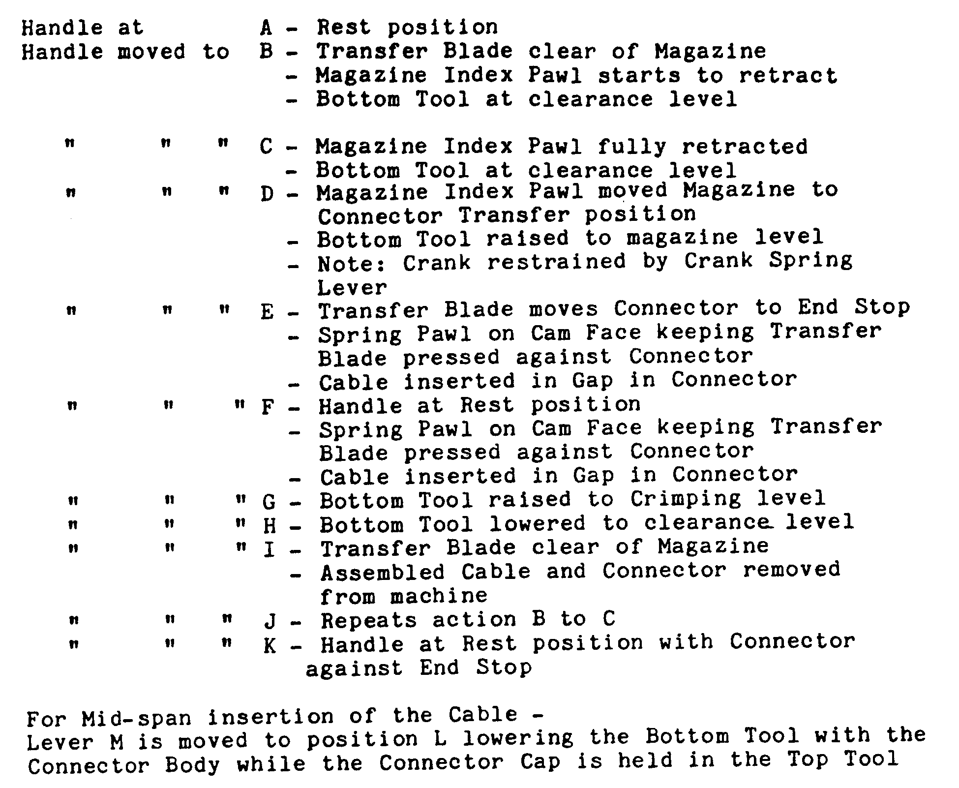
- Figure 5 shows schematically various stages in the operation.
- position A the apparatus is in a rest position with the sliding ram positioned between the press element 6 and 7 but with no connector in position.
- the various stages A to L correspond to different movements of the handle 5 of the control means 4 to achieve relative movements of various elements of the apparatus.
- the sliding ram is moved out from between the press elements and this is followed by indexing of the connector magazine 14 to bring a connector 13 into alignment with the ram 16 so that forward movement of the ram, as indicated by the arrow A, will move the ram into cooperation with a connector 13 to move this out of the magazine and towards the operative position 15 between the press element 6, 7.
- the ram 16 is held in its forward position to clamp the upper part of the connector 13 in the operative position.
- a ribbon cable 27 is then fed between the upper and lower parts of the connector 13.
- the lower press element 7 is moved downwardly, as described above, to separate the connector elements and allow insertion of the cable 27.
- the handle is then moved towards postion G in which the connector parts are crimped together to form the connector/cable assembly.
- movement of the press elements towards each other causes the plates 23, 24 to engage with shoulders 25, 26 of the element 6 thus flattening the cable before crimping occurs. This ensures correct alignment of respective conductors with a corresponding contact.
- the lower press element 7 is then moved downwardly whilst the assembled connector is held in position by the cooperation of the ram 16 and the front plate 17 (step H) and subsequent rearward movement of the ram 16 allows the assembled connector/cable to be removed from the apparatus.
- FIG 6 shows in detail one convenient form of control means 4.
- the control means 4 comprises the handle element 5 that is connected to a crank 28 by a suitable slipping friction clutch.
- a crank 28 Connected to a crank 28, to control movement thereof, is a spring biassed lever 29, that is connected at its outer end to the upper member 3 by a spring 30.
- the connecting rod 31 connects the crank 28 with one end of the pivoting rod 12, the other end of which cooperates with the element 8, to achieve the desired movement of the press element 7.
- the rod 12 is pivotally connected with the lower support member 2 by a pivot 32.
- a swivel plate 33 that is substantially triangular in shape, is rotatably mounted towards the rear of the support member 2, a pin 34 being provided to limit the carrier movement of the plate 33.
- the drive element 35 connects the plate 33 with the sliding ram 16.
- the drive element 35 being pivotally connected to the plate 33 at one end, and having at its other end a slot that receives a pin projecting downwardly of the sliding ram 16.
- a spring pawl 36 cooperates with the lower end of the drive element 35 to control movement thereof.
- the lower end of the drive element is profiled to present a cam surface 37 that cooperates with the spring pawl 36 to achieve control movement of the sliding ram 16 upon rotation of the plate 33.
- the plate 33 is connected to the handle element 5 by a connecting rod 38.
- the connecting rod 38 is pivotally connected at one end to the plate 33 and has a slot 39 towards its other end that receives a pin that projects it from an extension of the handle element 5, the pin 40 being urged towards the top of the stop 39 by
- Connecting means (not shown) are also provided between the control means 4 and an indexing mechanism for the magazine 14 so that appropriate movement of the handle 5 causes first a magazine pawl 42 to retract followed by indexing of the magazine 14. Relative movements of the elements of the control means is controlled by appropriately positioned stops, as illustrated in the Figures.
- Movement of the handle 5 to postion E causes the sliding ram 16 to move a connector 13 into the operative position to abut the end plate 17 and the spring pawl 36, of the plate 33, is caused to move up the cam face 37 thus urging the sliding ram against the connector 13 to hold this in the desired position.
- position F the rest position
- the action of the spring pawl 36 against the cam face 37 acts to retain pressure on the sliding ram 16 and thus to retain the connector 13 in the desired position.
- a ribbon cable (not shown) is fed into the gap between the connector parts.
- Subsequent movement of the handle to position G causes the rod 12 to pivot, moving its outer end upwardly and thus causing the lower press element 7 to be raised towards the press element 6 and thus to achieve crimping of the connector and cable.
- the apparatus is also useful for transverse, or mid-span, assembly of a connector and a cable.
- the above described steps are conducted up to handle position F, at which time, with the upper connector port held firmly between the ram 16 and end plate 17, the element 8 is rotated, cooperation between the rod 12 and the cam face of the element 8 allowing the element 8, and the press element 7, to move downwards to the clearance position.
- the connector parts are moved apart allowing transverse insertion of the cable. This is illustrated in Figure 6L.
- the crimping steps achieve to L are carried out.
- Any other convenient control means may be used.
- a pneumatic arrangement for achieving the desired movement of the press elements and indexing of the connector magazine could be used. Operation may be manual or automatic.
- Figure 7 to 10 illustrates the variety of forms of suitable magazines for retaining a store in connectors.
- the connectors may be contained in a flexible bandolier or, as shown in Figure 8, the connectors may be positioned in a magazine rack.
- connectors 13 are spaced from each other in a semi-rigid plastics film, each connector being held in a distinct-envelope part 40 of the bandolier.
- the ends of each envelope part 40 are open to allow the connector 13 to be moved from the bandolier to the operative position of the apparatus by the sliding ram 16.
- a dimpled area 41 projects inwardly from each side of each envelope part and acts to retain the desired separation between the connector parts.
- the bandolier may conveniently be provided in short strips or in longer lengths, for example in a roll. Any suitable indexing means, associated with the control means 4 may be used to sequentially bring connectors into alignment with the ram 16.
- apparatus of the invention may advantageously be used in combination with an automatic cable cutting machine.
- a cable cutter and clamp means or associated with the apparatus for cutting predetermined lengths of cable are positioned on one side of the press elements and a cable clamp is positioned on the opposite side of the press elements.
- a length of cable is fed sequentially through the cable clamp, between the upper and lower press element and the cutter means.
- the cable is locked in position, by operation of the clamp and is cut by operation of the cutter means.
- the cable may then be moved rearwardly so that the cut end is positioned between the press elements.
- the apparatus is then operated as above to crimp a connector adjacent the cut end of the cable.
- operation of the cutter means and the clamp is controlled by the same control means as the apparatus so that srequential automatic operation can be achieved.
- a cutter means may be provided in parallel between a pair of cooperating press elements, cable clamp being provided on the opposite side of each pair of press elements. The cutter operates as above allowing the simultaneous crimping of connectors adjacent each cut end.
Landscapes
- Engineering & Computer Science (AREA)
- Manufacturing & Machinery (AREA)
- Manufacturing Of Electrical Connectors (AREA)
- Coupling Device And Connection With Printed Circuit (AREA)
- Connecting Device With Holders (AREA)
- Package Frames And Binding Bands (AREA)
- Multi-Conductor Connections (AREA)
- Seal Device For Vehicle (AREA)
- Connector Housings Or Holding Contact Members (AREA)
- Connections By Means Of Piercing Elements, Nuts, Or Screws (AREA)
Abstract
Description
- THIS INVENTION relates to an apparatus for assembling two-part connectors. In particular, the invention relates to an apparatus for connecting two-part multiple plug and socket connectors to a multiple core strip cable.
- It is known to provide a cable in the form of a flat strip or ribbon in which a plurality of insulated conductors are arranged in side by side configuration. A wide variety of multiple plug and socket connectors are known for use with such cables. Generally the connectors have a plurality of contacts, one positioned to correspond with each of the conductors in a strip cable, and connection to the strip is made by causing the contacts to move into connection with a respective conductor of the cable by displacing the insulating material surrounding the conductor. Such connectors are known as insulation displacement contact connectors or IDC connectors. Typically, IDC connectors have a lower body portion, that may, for example form a plug for cooperation with a socket, and an upper cap portion. In the assembly of such connectors with a ribbon cable, the cable is appropriately positioned between the upper and lower connector portions which are subsequently brought towards one another, this movement causing the contacts to make connection with the conductors of the cable, by displacing insulating material, and, in a final position, to grip the cable firmly within the connector.
- Assembly of such a connector/cable arrangement is typically an essentially manual operation which is time consuming and unreliable. Apparatus has been proposed to mechanise the final clamping of the connector to a cable, for example using a pneumatic press. The use of such presses still requires manual assembly of the connector in relation to a cable.
- US-A-4245387 shows an example of a connector clamping press, in which one or more connector bases can be positioned manually and clamped, flat cable is laid on top of the or each connector base, a connector cover is laid on the cable over the respective connector base, a press positioned over the cover and operated to clamp the connector parts on to the flat cable.
- Machines have also been proposed for crimping one piece, hollow contacts on to conventional cables. For example, DE-A-1293594 shows a crimping press where a cable is fed into a cylindrical, hollow contact portion and the cable and the contact portion crimped together. The contacts are held in an advanceable magazine, the hollow portion which is crimped onto the cable extending free of the magazine.
- According to the invention, there is provided apparatus for assembling a pre-assembled two-part connector with an interposed cable, which apparatus comprises a pair of opposing, relatively movable press elements, storage means for containing a plurality of said connectors, means for moving a connector from said storage means to an operative position between the pair of press elements, means for actuating at least one of the press elements to achieve crimping of the connector and said interposed cable when the connector is in the operative position and means for individually holding each part of said two-part connector and movably separating said parts away from each other in detached relation so as to facilitate entry of said cable therebetween for subsequent crimping.
- In order that the invention may be more readily understood, and so that further features thereof may be appreciated, an embodiment of an apparatus of the invention will now be described, by way of example, with reference to the accompanying drawings, in which:-
- Figure 1 is a perspective voew of an apparatus of the invention;
- Figure 2 is a side elevation of the apparatus of Figure 1;
- Figure 3 is an end elevation of the apparatus of Figure 2;
- Figures 4a, b and c illustrate various stages in the assembly of the connector;
- Figures 5A to I illustrates schematically the operating faces of the apparatus;
- Figure 6A to L illustrates one preferred operation and control means for the invention; and
- Figures 7 to 10 illustrate a variety of alternative connector supply arrangement for use with the apparatus of the invention.
- Referring to Figure 1 an apparatus embodying the invention is generally indicated at 1. The apparatus 1 comprises a
lower support member 2 and anupper press member 3. Thepress member 3 is held in a fixed position relative to thesupport member 2. Operation of the apparatus is achieved by actuation of a control means generally indicated 4, one form of which will be described in detail hereinbelow. The control means 4 includes an operating handle 5. - At a forward end, the apparatus 1 has upper and
lower press elements upper press element 6 is fixedly connected to themember 3 and projects downwardly towards thesupport member 2. Thelower press element 7 is positioned at an outer upper end region of thesupport member 2 and defines an upwardly facing anvil for cooperation with thepress element 6. Thelower press element 7 cooperates with thesupport member 2 but is movable in a substantially vertical direction with respect thereto from an operating position, as shown in Figure 1, to an upper crimping position, best seen in Figure 6g, and to a lower clearance position best seen in Figure 61. The relative position of thepress element 7 is controlled by apivoting element 8 having a projection 9 that cooperates with asupport pin 10 connected to theelement 7. In its lower region, theelement 8 presents a cam surface 11 that cooperates with anarm 12 of the control means 4. Theelement 8 is normally maintained in an upright position, as shown in Figure 1. Thearm 12 is pivotable so that, on appropriate movement of the control means 4, the end of thearm 12 that cooperates with the lower region of theelement 8 is moved upwardly, causing theelement 8 and thus thepress element 7 to move from the operative position to the crimping position. Theelement 8 may be pivoted, using ahandle 8a, to a second, inclined, position the cooperation between the cam surface 11 and thearm 12 allowing theelement 7 to move in a downward direction to the clearance position. - A connector storage and feed mechanism is positioned between the
members connectors 13 from amagazine 14 to the operative position, indicated 15, between thepress elements - The
connectors 13 are held within themagazine 14 in a connected but spaced-apart arrangement that enables a ribbon cable to be fed between the spaced apart elements before these are clamped to achieve the desired connection. Asliding ram 16, that is operated by the control means 4, is operative to move aselected connector 13 out from themagazine 14 into theoperative position 15. As best seen in Figure 2, astop plate 17 projects downwardly from an outer end face of thepress element 6 to limit movement of theconnector 13 and thus to position theconnector 13 for clamping in theoperating region 15. When thesliding ram 16 urges aconnector 13 towards and into engagement with theend plate 17 the connector is locked in position by cooperation between theend plates 17 and theram 16. - As best shown in Figure 3, the
lower press element 7 comprisessupport plates 18, that extend outwardly to form a substantially T-section element. Theplates 18 provide support and guidance for a ribbon cable to be inserted between the upper and lower parts of aconnector 13 when this is in theoperative position 15, and additionally,edge guides 19 project upwardly from an upper surface of theplates 18 to facilitate correct positioning of the cable. It will be appreciated that by appropriate positioning of theedge guides 19 and theend plate 17 correct alignment of the ribbon cable with aconnector 13 can be achieved, irrespective of the width of the connector and cable. - Referring again to Figure 3, a lower retaining means 20 comprising a
fixed side stop 21 and a spring biassedclamp 22, acts to retain the lower connector body in fixed relation to the upper cap part. Spring biassedplates plates 18, on either side of theoperative position 15. When a cable is in position and thelower press element 7 is moved towards theupper press element 6 theplates projections press element 6 to flatten and hold the cable in the correct orientation. - Referring to Figures 2 and 4 operation of the apparatus will be described briefly. As described in detail later, the operation of the handle 5, causes the
sliding ram 16 to move aconnector 13 from themagazine 14 to theoperative position 15, where it is held by cooperation with the forward end of theram 16 and the dependingend plate 17. This position is indicated in the dotted lines in Figure 2. A flat ribbon cable is then fed between the spaced apart upper and lower portions of the connector and when this has been appropriately positioned, the handle 5 is operated to cause thepress element 7 to move towards thepress element 6 and thus to move the upper part of theconnector 13 from its insertion level, as shown in Figure 4b, to the crimping position as shown in Figure 4a. Further operation of the handle 5 releases thecrimped connector 13 following which thepress element 7 is lowered allowing the crimped connector and cable to be removed easily from the apparatus. - In situations where the ends of the ribbon cable are obstructed, for example by another previously positioned connector, and thus the cable cannot be fed through the
connector 13 in its spaced apart but connected arrangement, the apparatus provides a further operating step to allow the two parts of the connector to be separated to permit a cable to be inserted between the respective connector parts in a transverse direction. To achieve this operation a connector is moved into theoperative position 15 as in the previously described operation. In this position the upper part of the connector is held fixed by theram 16 and theplate 17 whilst the lower part is firmly held by theside plate 21 and spring retaining means 22. Prior to the crimping operation, and with the two parts fixed as described, operation of thepivot element 8 to move thepress element 7 downwardly causes a separation of the connector parts allowing insertion of the ribbon cable. When the cable is appropriately positioned theelement 8 is again actuated to move thepress element 7 back to its operative position. It should be appreciated that as the upper and lower parts of theconnector 13 are gripped separately and the apparatus parts are constrained to move in fixed directions, correct alignment of the upper and lower parts will be maintained during the separation and re-connection phases. The cable can be correctly aligned using theedge guides 19 and the connector and cable can be crimped together as described above. - Figure 5 shows schematically various stages in the operation. In position A the apparatus is in a rest position with the sliding ram positioned between the
press element - At B the sliding ram is moved out from between the press elements and this is followed by indexing of the
connector magazine 14 to bring aconnector 13 into alignment with theram 16 so that forward movement of the ram, as indicated by the arrow A, will move the ram into cooperation with aconnector 13 to move this out of the magazine and towards theoperative position 15 between thepress element ram 16 is held in its forward position to clamp the upper part of theconnector 13 in the operative position. Continuing to F, aribbon cable 27 is then fed between the upper and lower parts of theconnector 13. Alternatively, if thecable 27 is to be fed transversely into theconnector 13 thelower press element 7 is moved downwardly, as described above, to separate the connector elements and allow insertion of thecable 27. The handle is then moved towards postion G in which the connector parts are crimped together to form the connector/cable assembly. As indicated in Figure G1, movement of the press elements towards each other causes theplates shoulders element 6 thus flattening the cable before crimping occurs. This ensures correct alignment of respective conductors with a corresponding contact. Thelower press element 7 is then moved downwardly whilst the assembled connector is held in position by the cooperation of theram 16 and the front plate 17 ( step H) and subsequent rearward movement of theram 16 allows the assembled connector/cable to be removed from the apparatus. - Figure 6 shows in detail one convenient form of control means 4. Referring firstly to Figure 6a, the control means 4 comprises the handle element 5 that is connected to a crank 28 by a suitable slipping friction clutch. Connected to a crank 28, to control movement thereof, is a spring
biassed lever 29, that is connected at its outer end to theupper member 3 by aspring 30. The connectingrod 31 connects thecrank 28 with one end of the pivotingrod 12, the other end of which cooperates with theelement 8, to achieve the desired movement of thepress element 7. Therod 12 is pivotally connected with thelower support member 2 by apivot 32. - A
swivel plate 33, that is substantially triangular in shape, is rotatably mounted towards the rear of thesupport member 2, apin 34 being provided to limit the carrier movement of theplate 33. Thedrive element 35 connects theplate 33 with the slidingram 16. Thedrive element 35 being pivotally connected to theplate 33 at one end, and having at its other end a slot that receives a pin projecting downwardly of the slidingram 16. Aspring pawl 36 cooperates with the lower end of thedrive element 35 to control movement thereof. For this purpose, the lower end of the drive element is profiled to present acam surface 37 that cooperates with thespring pawl 36 to achieve control movement of the slidingram 16 upon rotation of theplate 33. Theplate 33 is connected to the handle element 5 by a connectingrod 38. The connectingrod 38 is pivotally connected at one end to theplate 33 and has aslot 39 towards its other end that receives a pin that projects it from an extension of the handle element 5, thepin 40 being urged towards the top of thestop 39 by aspring 41. - Connecting means (not shown) are also provided between the control means 4 and an indexing mechanism for the
magazine 14 so that appropriate movement of the handle 5 causes first amagazine pawl 42 to retract followed by indexing of themagazine 14. Relative movements of the elements of the control means is controlled by appropriately positioned stops, as illustrated in the Figures. - Operation of the control means will be best appreciated by consideration of Figures 6a to l, the reference letters corresponding to movement positions of the handle 5, as illustrated in Figure 6a. The reference letters used in Figure 6 correspond to those used when describing the general operation of the apparatus with reference to Figure 5.
- When the handle is in position A the apparatus is in its rest position. Movement of the handle to position B causes the sliding
ram 16 to move away from its rest position and clear of themagazine 14. As soon as theram 16 is clear of themagazine 14 themagazine pawl 42 begins to retract and thepress element 7 moves to its lower clearance level. Movement of handle to position C causes full retraction of the magazine pawl and subsequent movement of the handle to position D causes indexing of the magazine to bring a connector into alignment with theram 16. At this time thepress element 7 is returned to its upward position and thecrank 28 is restrained from further movement by a stop pin on thecrank pin lever 29. - Movement of the handle 5 to postion E causes the sliding
ram 16 to move aconnector 13 into the operative position to abut theend plate 17 and thespring pawl 36, of theplate 33, is caused to move up thecam face 37 thus urging the sliding ram against theconnector 13 to hold this in the desired position. As the handle is moved to position F (the rest position) the action of thespring pawl 36 against the cam face 37 acts to retain pressure on the slidingram 16 and thus to retain theconnector 13 in the desired position. In this position a ribbon cable (not shown) is fed into the gap between the connector parts. Subsequent movement of the handle to position G causes therod 12 to pivot, moving its outer end upwardly and thus causing thelower press element 7 to be raised towards thepress element 6 and thus to achieve crimping of the connector and cable. - Return movement of the handle to position H moves the
press element 7 towards its clearance position whilst maintaining pressure on theram 16 to retain the crimpedconnector 13 in position between theram 16 and theend plate 17. Further movement of the handle to position 1 causes retraction of the slidingram 6 allowing removal of the assembled cable and connector from the apparatus. - As explained, the apparatus is also useful for transverse, or mid-span, assembly of a connector and a cable. To achieve such assembly the above described steps are conducted up to handle position F, at which time, with the upper connector port held firmly between the
ram 16 andend plate 17, theelement 8 is rotated, cooperation between therod 12 and the cam face of theelement 8 allowing theelement 8, and thepress element 7, to move downwards to the clearance position. As the lower connector part is held firmly in position on thelower press element 7, the connector parts are moved apart allowing transverse insertion of the cable. This is illustrated in Figure 6L. When theelement 8 is returned to its original position the crimping steps achieve to L are carried out. - Any other convenient control means may be used. For example a pneumatic arrangement for achieving the desired movement of the press elements and indexing of the connector magazine could be used. Operation may be manual or automatic.
- Figure 7 to 10 illustrates the variety of forms of suitable magazines for retaining a store in connectors. As shown in Figure 7A and B the connectors may be contained in a flexible bandolier or, as shown in Figure 8, the connectors may be positioned in a magazine rack.
- Whilst the embodiment illustrated in Figures 1 to 6 shows an arrangement of the apparatus suitable for use with a magazine
rack containing connectors 13 it will be appreciated that only minor modifications to the described arrangement are required to enable the use of a flexible bandolier, such as that illustrated in Figure 7. In order that the connectors are presented in the desired upright configuration appropriate access apertures may be provided in themembers - Considering the bandolier arrangement of Figure 7, it will be seen that
connectors 13 are spaced from each other in a semi-rigid plastics film, each connector being held in a distinct-envelope part 40 of the bandolier. The ends of eachenvelope part 40 are open to allow theconnector 13 to be moved from the bandolier to the operative position of the apparatus by the slidingram 16. Adimpled area 41 projects inwardly from each side of each envelope part and acts to retain the desired separation between the connector parts. The bandolier may conveniently be provided in short strips or in longer lengths, for example in a roll. Any suitable indexing means, associated with the control means 4 may be used to sequentially bring connectors into alignment with theram 16. - Whilst suitable for use alone, apparatus of the invention may advantageously be used in combination with an automatic cable cutting machine. For example, in one particularly preferred arrangement a cable cutter and clamp means or associated with the apparatus for cutting predetermined lengths of cable. In such an arrangement (not shown) a cable cutter is positioned on one side of the press elements and a cable clamp is positioned on the opposite side of the press elements.
- In operation a length of cable is fed sequentially through the cable clamp, between the upper and lower press element and the cutter means. The cable is locked in position, by operation of the clamp and is cut by operation of the cutter means. The cable may then be moved rearwardly so that the cut end is positioned between the press elements. The apparatus is then operated as above to crimp a connector adjacent the cut end of the cable.
- Desirably, operation of the cutter means and the clamp is controlled by the same control means as the apparatus so that srequential automatic operation can be achieved.
- In another arrangement a cutter means may be provided in parallel between a pair of cooperating press elements, cable clamp being provided on the opposite side of each pair of press elements. The cutter operates as above allowing the simultaneous crimping of connectors adjacent each cut end.
- The features disclosed in the foregoing description, in the following claims and/or in the accompanying drawings may, both separately and in any combination thereof, be material for realising the invention in diverse forms thereof.
- Operational steps according to figures 5 and 6 :
Claims (17)
- Apparatus for assembling a pre-assembled two-part connector (13) with an interposed cable (27), which apparatus comprises a pair of opposing, relatively movable press elements (6,7), storage means (14) for containing a plurality of said connectors (13), means (16) for moving a connector from said storage means (14) to an operative position (15) between the pair of press elements (6,7), means (5) for actuating at least one of the press elements to achieve crimping of the connector (13) and said interposed cable (27) when the connector (13) is in the operative position (15) and means (16,17; 21,22) for individually holding each part of said two-part connector (13) and movably separating said parts away from each other in detached relation so as to facilitate entry of said cable (27) therebetween for subsequent crimping.
- Apparatus as claimed in Claim 1 wherein the connector moving means comprises a sliding ram (16) and wherein said holding means for one respective part of said two-part connector (13) comprises said sliding ram (16) and a plate (17) cooperating to provide a clamp for said one part.
- Apparatus as claimed in Claim 1 or Claim 2 wherein said holding means for the other respective part of said two-part connector comprises a stop means (21) on one of said press elements and a movable spring biased member (22) for cooperating to clamp said other part.
- Apparatus as claimed in any one of Claims 1 to 3 comprising common control means (5,16,28,29,3,31,12) for selectively causing movement of the connector (13) into the operative position (15) and crimping movement of the press elements (6,7) and for controlling said means (16,17; 21,22) for individually holding and movably separating each part of said connector (13) after the connector has been moved to the operative position (15).
- Apparatus as claimed in any one of Claims 1 to 4 wherein the control means comprises a lever arrangement, operation of which is achieved by handle means (5).
- Apparatus as claimed in Claim 4 wherein said common control means comprises a linkage mechanism (5,16,28,29, 3,31,12) including a sliding ram (16) a movable element (7) selected from said pair of press elements (6,7) and a handle actuator (5), all mechanically intercoupled to each other.
- Apparatus as claimed in Claim 4 or Claim 6 whrein said common control means (5,16,28,29,3,31,12) further includes means for indexing a connector (13) from said storage means (14) for movement into said operative position.
- Apparatus as claimed in any one of Claims 4, 6, 7 and 8 wherein said common control means further includes means (16,17; 21,22) for holding said connector (13) in a fixed position in said operative position (15) to facilitate crimping of said connector (13) and said cable (27).
- Apparatus as claimed in any one of Claims 1 to 8 wherein one press element (6) lies above the other press element (7), the upper press element (6) being fixed and the lower press element (7) being movable.
- Apparatus as claimed in any one of Claims 1 to 9 wherein the storage means comprises a magazine rack (14).
- Apparatus as claimed in any one of Claims 1 to 9 wherein the storage means comprises a bandolier.
- Apparatus as claimed in any one of Claims 1 to 11 comprising guide means (19) for aligning a cable (27) with a connector (13) when the connector (13) is in the operative position (15).
- Apparatus as claimed in Claim 12 wherein the pair of press elements (6,7) define upper (6) and lower (7) press elements respectively and wherein the lower press element (7) is substantially T-shaped and the guide means (19) are provided on an upper face of said lower press element (7) and on each side of the operative position (15).
- Apparatus as claimed in any one of Claims 1 to 13 comprising means (23,24) for engaging said cable (27) at spaced locations, each of said means (23,24) for engaging said cable (27) being situated at opposite sides of said connector (13) when in said operative position (15) to hold and flatten said cable (27) against one of said press elements (7) for connection to said connector (13).
- Apparatus as claimed in Claim 14 wherein said engaging means (23,24) comprises a pair of spaced spring biased plates (23,24) disposed on one of said press elements (7) and being responsive to the relative movement of said press elements (6,7) for biasing said cable (27) against the other of said press elements (6).
- Apparatus as claimed in any one of Claims 1 to 13 comprising spring biased means (23,24) for flattening the cable (27) immediately prior to crimping of the connector (13).
- Apparatus as claimed in Claim 16 wherein the spring biased means (23,24) are provided on one of the press elements (7) and cooperate with depending shoulders (25,26) on the other of the press elements (6) to achieve the desired cable flattening.
Priority Applications (1)
| Application Number | Priority Date | Filing Date | Title |
|---|---|---|---|
| AT85305613T ATE82653T1 (en) | 1984-08-17 | 1985-08-07 | DEVICE FOR ASSEMBLING TWO-PIECE CONNECTORS. |
Applications Claiming Priority (2)
| Application Number | Priority Date | Filing Date | Title |
|---|---|---|---|
| GB8420977 | 1984-08-17 | ||
| GB848420977A GB8420977D0 (en) | 1984-08-17 | 1984-08-17 | Assembling twopart connectors |
Related Child Applications (1)
| Application Number | Title | Priority Date | Filing Date |
|---|---|---|---|
| EP88201850.0 Division-Into | 1985-08-07 |
Publications (3)
| Publication Number | Publication Date |
|---|---|
| EP0171993A2 EP0171993A2 (en) | 1986-02-19 |
| EP0171993A3 EP0171993A3 (en) | 1987-12-09 |
| EP0171993B1 true EP0171993B1 (en) | 1992-11-19 |
Family
ID=10565497
Family Applications (2)
| Application Number | Title | Priority Date | Filing Date |
|---|---|---|---|
| EP85305613A Expired - Lifetime EP0171993B1 (en) | 1984-08-17 | 1985-08-07 | Improvements in or relating to apparatus for assembling two-part connectors |
| EP88201850A Expired - Lifetime EP0318065B1 (en) | 1984-08-17 | 1985-08-07 | Bandolier for two-part connectors |
Family Applications After (1)
| Application Number | Title | Priority Date | Filing Date |
|---|---|---|---|
| EP88201850A Expired - Lifetime EP0318065B1 (en) | 1984-08-17 | 1985-08-07 | Bandolier for two-part connectors |
Country Status (7)
| Country | Link |
|---|---|
| US (2) | US4765059A (en) |
| EP (2) | EP0171993B1 (en) |
| JP (2) | JPS6217972A (en) |
| AT (1) | ATE82653T1 (en) |
| CA (1) | CA1263010A (en) |
| DE (2) | DE3586837T2 (en) |
| GB (1) | GB8420977D0 (en) |
Families Citing this family (8)
| Publication number | Priority date | Publication date | Assignee | Title |
|---|---|---|---|---|
| US4852248A (en) * | 1985-02-19 | 1989-08-01 | Burndy Corporation | Connector installation station for compact semi-automatic cable assembly system |
| US5072517A (en) * | 1991-06-06 | 1991-12-17 | Minnesota Mining And Manufacturing Company | Apparatus for retaining a two-piece connector for attachment to a flat multiconductor electrical cable |
| US5475916A (en) * | 1994-11-21 | 1995-12-19 | The Whitaker Corporation | Machine for staking a two part connector housing together |
| TW553187U (en) * | 2002-07-26 | 2003-09-11 | Hon Hai Prec Ind Co Ltd | Packing device |
| US6805169B2 (en) | 2002-09-30 | 2004-10-19 | Tyco Electronic Corporation | Method and apparatus for wire splicing |
| US8336197B2 (en) * | 2009-01-26 | 2012-12-25 | Andrew, Llc | Coaxial cable connector attaching tool having connecting seating indicator |
| US8166639B2 (en) * | 2009-01-26 | 2012-05-01 | Andrew, Llc | Coaxial cable connector attaching tool having connector magazine |
| KR100983803B1 (en) * | 2010-05-04 | 2010-09-27 | 김관하 | Bandolier pin manufacturing apparatus |
Family Cites Families (31)
| Publication number | Priority date | Publication date | Assignee | Title |
|---|---|---|---|---|
| US2613432A (en) * | 1947-06-13 | 1952-10-14 | Gilbert Margaret Doris | Machine for assembling electrical connectors |
| NL245653A (en) * | 1958-11-24 | |||
| US3152390A (en) * | 1962-09-04 | 1964-10-13 | Amp Inc | Electrical connector applying tool |
| US3264860A (en) * | 1964-02-03 | 1966-08-09 | Thomas & Betts Company Inc | Wire guides for terminal attaching machines |
| NL134665C (en) * | 1965-04-28 | |||
| US3430809A (en) * | 1967-07-13 | 1969-03-04 | Harold J Vanstrom | Metered parts dispensing cartridge |
| US3443683A (en) * | 1968-04-17 | 1969-05-13 | Amp Inc | Package facilitating assembly of connector elements onto cable |
| US3444993A (en) * | 1968-04-23 | 1969-05-20 | Thomas J Lunsford | Component package with dust cover |
| US3710610A (en) * | 1970-06-05 | 1973-01-16 | Bunker Ramo | Wire terminal crimping tool |
| NL7113223A (en) * | 1971-09-25 | 1973-03-27 | ||
| US3840840A (en) * | 1973-08-10 | 1974-10-08 | Continental Wirt Electronic | Flat conductor cable connector |
| US4020540A (en) * | 1976-02-26 | 1977-05-03 | Amp Incorporated | Applicator tool |
| US4064624A (en) * | 1976-06-16 | 1977-12-27 | International Telephone And Telegraph Corporation | Separable funnel guide and crimping die assembly |
| JPS5599795A (en) * | 1979-01-25 | 1980-07-30 | Matsushita Electric Industrial Co Ltd | Device for mounting electronic part |
| US4245387A (en) * | 1979-06-14 | 1981-01-20 | Minnesota Mining And Manufacturing Company | Cable harness assembly fixture |
| US4286381A (en) * | 1979-12-21 | 1981-09-01 | Amp Incorporated | Terminating tool |
| US4332083A (en) * | 1980-05-15 | 1982-06-01 | Amp Incorporated | Terminating apparatus for flat cable |
| US4361942A (en) * | 1980-09-23 | 1982-12-07 | Ark-Les Corporation | Terminal applying machine |
| US4393580A (en) * | 1981-02-05 | 1983-07-19 | Amp Incorporated | One step applicator tool |
| JPS587033A (en) * | 1981-07-07 | 1983-01-14 | Takenaka Komuten Co Ltd | Constructing method for foundation endurable to concentrated load employing soft ground mixture processing method |
| JPS5832915A (en) * | 1981-08-24 | 1983-02-26 | Honda Motor Co Ltd | Exhaust gas purifier of internal-combustion engine |
| US4517718A (en) * | 1981-08-31 | 1985-05-21 | Amp Incorporated | Cable clamping and orienting apparatus |
| FR2521358A1 (en) * | 1982-02-10 | 1983-08-12 | Amp France | METHOD AND APPARATUS FOR COUPLING AN INSULATING CONNECTOR HOUSING AND A COVER FOR THIS HOUSING TO PROVIDE A TERMINATION ON AN ELECTRICAL CONDUCTOR |
| US4580340A (en) * | 1982-02-23 | 1986-04-08 | Shields Charles E | Method and apparatus for applying two piece connector blocks to multiconductor cable |
| US4481710A (en) * | 1982-10-28 | 1984-11-13 | Panduit Corp. | Tool for applying connectors |
| US4706812A (en) * | 1982-12-13 | 1987-11-17 | Texas Instruments Incorporated | Shipping and dispensing package for a series of articles |
| US4488353A (en) * | 1983-02-04 | 1984-12-18 | Panduit Corp. | Termination tooling for applying connectors to flat cable |
| US4554733A (en) * | 1983-02-28 | 1985-11-26 | Panduit Corp. | Termination tooling for applying connectors to flat cable |
| IT1160828B (en) * | 1983-03-23 | 1987-03-11 | Atb Spa | PROTECTIVE LOADER PACKAGING IN PARTICULAR FOR SURFACE-DAMAGING SENSITIVE PRODUCTS |
| US4549343A (en) * | 1983-09-02 | 1985-10-29 | Amp Incorporated | Applicator for installing two part connector assemblies in cables |
| JPS60144298U (en) * | 1984-03-05 | 1985-09-25 | 株式会社村田製作所 | Chip-type electronic components |
-
1984
- 1984-08-17 GB GB848420977A patent/GB8420977D0/en active Pending
-
1985
- 1985-08-07 AT AT85305613T patent/ATE82653T1/en not_active IP Right Cessation
- 1985-08-07 DE DE8585305613T patent/DE3586837T2/en not_active Expired - Fee Related
- 1985-08-07 EP EP85305613A patent/EP0171993B1/en not_active Expired - Lifetime
- 1985-08-07 EP EP88201850A patent/EP0318065B1/en not_active Expired - Lifetime
- 1985-08-07 DE DE8888201850T patent/DE3586725T2/en not_active Expired - Fee Related
- 1985-08-16 CA CA000488861A patent/CA1263010A/en not_active Expired
- 1985-08-16 JP JP60179509A patent/JPS6217972A/en active Granted
-
1987
- 1987-02-27 US US07/019,803 patent/US4765059A/en not_active Expired - Lifetime
- 1987-02-27 US US07/019,830 patent/US4827608A/en not_active Expired - Fee Related
-
1990
- 1990-01-31 JP JP2019371A patent/JPH03138881A/en active Granted
Also Published As
| Publication number | Publication date |
|---|---|
| CA1263010A (en) | 1989-11-21 |
| US4765059A (en) | 1988-08-23 |
| JPH0576756B2 (en) | 1993-10-25 |
| US4827608A (en) | 1989-05-09 |
| JPS6217972A (en) | 1987-01-26 |
| EP0171993A3 (en) | 1987-12-09 |
| DE3586725D1 (en) | 1992-11-05 |
| EP0318065A1 (en) | 1989-05-31 |
| GB8420977D0 (en) | 1984-09-19 |
| EP0318065B1 (en) | 1992-09-30 |
| DE3586837T2 (en) | 1993-05-19 |
| ATE82653T1 (en) | 1992-12-15 |
| JPH03138881A (en) | 1991-06-13 |
| DE3586837D1 (en) | 1992-12-24 |
| JPH0577158B2 (en) | 1993-10-26 |
| DE3586725T2 (en) | 1993-04-22 |
| EP0171993A2 (en) | 1986-02-19 |
Similar Documents
| Publication | Publication Date | Title |
|---|---|---|
| US4043017A (en) | Apparatus for inserting wires into terminals and for manufacturing electrical harnesses | |
| US3766622A (en) | Automatic apparatus for attaching wires to terminals | |
| US4290179A (en) | Cable harness assembly machine | |
| WO2009109740A2 (en) | Termination tool with corresponding male and female connectors | |
| US4765059A (en) | Apparatus for assembling two-part connectors | |
| US3588984A (en) | Stripping and crimping apparatus | |
| US3659328A (en) | Stripping and crimping apparatus | |
| EP0190821A2 (en) | Apparatus for connecting electrical connectors to cable | |
| EP0001891B1 (en) | Apparatus for inserting wires into electrical terminals | |
| US4525927A (en) | Method and apparatus for connecting an insulating housing of a connector and a cover | |
| US11837835B2 (en) | Terminal feeding assembly of a crimping machine | |
| CA1058843A (en) | Termination tool for multi-wire connectors | |
| US4598570A (en) | Apparatus for crimping electric terminals | |
| US4429455A (en) | Connector application machine | |
| CA1294766C (en) | Bandolier assembly for two-part connector assembly apparatus | |
| EP0375458A1 (en) | The stripping and terminating of conductors in multi core cables | |
| EP0001678B1 (en) | Wire deploying apparatus | |
| US5457876A (en) | Conductor guide mechanism in a tool for terminating conductors of a cable to a connector | |
| EP0145215A2 (en) | Cable harness assembly apparatus | |
| US4506440A (en) | Wiring tool for wiring electric multi-pin plug-in connectors, connector strips or the like using clamp-cutting techniques | |
| US3962901A (en) | Electrical connector tap assembly apparatus | |
| US20050071992A1 (en) | Manual machine for attaching an insulation displacement type connector | |
| US5109590A (en) | Multi core cable stripping | |
| GB2226781A (en) | Flat cable positioning tray | |
| JPH0145953B2 (en) |
Legal Events
| Date | Code | Title | Description |
|---|---|---|---|
| PUAI | Public reference made under article 153(3) epc to a published international application that has entered the european phase |
Free format text: ORIGINAL CODE: 0009012 |
|
| AK | Designated contracting states |
Kind code of ref document: A2 Designated state(s): AT BE CH DE FR GB IT LI LU NL SE |
|
| RAP1 | Party data changed (applicant data changed or rights of an application transferred) |
Owner name: THOMAS & BETTS CORPORATION |
|
| PUAL | Search report despatched |
Free format text: ORIGINAL CODE: 0009013 |
|
| AK | Designated contracting states |
Kind code of ref document: A3 Designated state(s): AT BE CH DE FR GB IT LI LU NL SE |
|
| 17P | Request for examination filed |
Effective date: 19880511 |
|
| RAP1 | Party data changed (applicant data changed or rights of an application transferred) |
Owner name: THOMAS & BETTS INTERNATIONAL INC. |
|
| 17Q | First examination report despatched |
Effective date: 19901001 |
|
| GRAA | (expected) grant |
Free format text: ORIGINAL CODE: 0009210 |
|
| AK | Designated contracting states |
Kind code of ref document: B1 Designated state(s): AT BE CH DE FR GB IT LI LU NL SE |
|
| PG25 | Lapsed in a contracting state [announced via postgrant information from national office to epo] |
Ref country code: SE Effective date: 19921119 Ref country code: NL Effective date: 19921119 Ref country code: LI Effective date: 19921119 Ref country code: CH Effective date: 19921119 Ref country code: BE Effective date: 19921119 Ref country code: AT Effective date: 19921119 |
|
| REF | Corresponds to: |
Ref document number: 82653 Country of ref document: AT Date of ref document: 19921215 Kind code of ref document: T |
|
| ET | Fr: translation filed | ||
| REF | Corresponds to: |
Ref document number: 3586837 Country of ref document: DE Date of ref document: 19921224 |
|
| ITF | It: translation for a ep patent filed | ||
| REG | Reference to a national code |
Ref country code: CH Ref legal event code: PL |
|
| NLV1 | Nl: lapsed or annulled due to failure to fulfill the requirements of art. 29p and 29m of the patents act | ||
| PLBE | No opposition filed within time limit |
Free format text: ORIGINAL CODE: 0009261 |
|
| STAA | Information on the status of an ep patent application or granted ep patent |
Free format text: STATUS: NO OPPOSITION FILED WITHIN TIME LIMIT |
|
| 26N | No opposition filed | ||
| EPTA | Lu: last paid annual fee | ||
| PGFP | Annual fee paid to national office [announced via postgrant information from national office to epo] |
Ref country code: LU Payment date: 19960701 Year of fee payment: 12 |
|
| PGFP | Annual fee paid to national office [announced via postgrant information from national office to epo] |
Ref country code: FR Payment date: 19960715 Year of fee payment: 12 |
|
| PGFP | Annual fee paid to national office [announced via postgrant information from national office to epo] |
Ref country code: DE Payment date: 19960716 Year of fee payment: 12 |
|
| PGFP | Annual fee paid to national office [announced via postgrant information from national office to epo] |
Ref country code: GB Payment date: 19960724 Year of fee payment: 12 |
|
| PG25 | Lapsed in a contracting state [announced via postgrant information from national office to epo] |
Ref country code: LU Free format text: LAPSE BECAUSE OF NON-PAYMENT OF DUE FEES Effective date: 19970807 Ref country code: GB Free format text: LAPSE BECAUSE OF NON-PAYMENT OF DUE FEES Effective date: 19970807 |
|
| GBPC | Gb: european patent ceased through non-payment of renewal fee |
Effective date: 19970807 |
|
| PG25 | Lapsed in a contracting state [announced via postgrant information from national office to epo] |
Ref country code: FR Free format text: LAPSE BECAUSE OF NON-PAYMENT OF DUE FEES Effective date: 19980430 |
|
| PG25 | Lapsed in a contracting state [announced via postgrant information from national office to epo] |
Ref country code: DE Free format text: LAPSE BECAUSE OF NON-PAYMENT OF DUE FEES Effective date: 19980501 |
|
| REG | Reference to a national code |
Ref country code: FR Ref legal event code: ST |