EP0170503A2 - Ground treatment - Google Patents
Ground treatment Download PDFInfo
- Publication number
- EP0170503A2 EP0170503A2 EP85305321A EP85305321A EP0170503A2 EP 0170503 A2 EP0170503 A2 EP 0170503A2 EP 85305321 A EP85305321 A EP 85305321A EP 85305321 A EP85305321 A EP 85305321A EP 0170503 A2 EP0170503 A2 EP 0170503A2
- Authority
- EP
- European Patent Office
- Prior art keywords
- stone
- tube
- inner tube
- ground
- outer tube
- Prior art date
- Legal status (The legal status is an assumption and is not a legal conclusion. Google has not performed a legal analysis and makes no representation as to the accuracy of the status listed.)
- Granted
Links
Images


Classifications
-
- E—FIXED CONSTRUCTIONS
- E02—HYDRAULIC ENGINEERING; FOUNDATIONS; SOIL SHIFTING
- E02D—FOUNDATIONS; EXCAVATIONS; EMBANKMENTS; UNDERGROUND OR UNDERWATER STRUCTURES
- E02D5/00—Bulkheads, piles, or other structural elements specially adapted to foundation engineering
- E02D5/22—Piles
- E02D5/34—Concrete or concrete-like piles cast in position ; Apparatus for making same
- E02D5/38—Concrete or concrete-like piles cast in position ; Apparatus for making same making by use of mould-pipes or other moulds
- E02D5/44—Concrete or concrete-like piles cast in position ; Apparatus for making same making by use of mould-pipes or other moulds with enlarged footing or enlargements at the bottom of the pile
-
- E—FIXED CONSTRUCTIONS
- E02—HYDRAULIC ENGINEERING; FOUNDATIONS; SOIL SHIFTING
- E02D—FOUNDATIONS; EXCAVATIONS; EMBANKMENTS; UNDERGROUND OR UNDERWATER STRUCTURES
- E02D3/00—Improving or preserving soil or rock, e.g. preserving permafrost soil
- E02D3/02—Improving by compacting
- E02D3/08—Improving by compacting by inserting stones or lost bodies, e.g. compaction piles
-
- E—FIXED CONSTRUCTIONS
- E02—HYDRAULIC ENGINEERING; FOUNDATIONS; SOIL SHIFTING
- E02D—FOUNDATIONS; EXCAVATIONS; EMBANKMENTS; UNDERGROUND OR UNDERWATER STRUCTURES
- E02D5/00—Bulkheads, piles, or other structural elements specially adapted to foundation engineering
- E02D5/22—Piles
- E02D5/34—Concrete or concrete-like piles cast in position ; Apparatus for making same
- E02D5/38—Concrete or concrete-like piles cast in position ; Apparatus for making same making by use of mould-pipes or other moulds
- E02D5/385—Concrete or concrete-like piles cast in position ; Apparatus for making same making by use of mould-pipes or other moulds with removal of the outer mould-pipes
-
- E—FIXED CONSTRUCTIONS
- E02—HYDRAULIC ENGINEERING; FOUNDATIONS; SOIL SHIFTING
- E02D—FOUNDATIONS; EXCAVATIONS; EMBANKMENTS; UNDERGROUND OR UNDERWATER STRUCTURES
- E02D5/00—Bulkheads, piles, or other structural elements specially adapted to foundation engineering
- E02D5/22—Piles
- E02D5/48—Piles varying in construction along their length, i.e. along the body between head and shoe, e.g. made of different materials along their length
-
- E—FIXED CONSTRUCTIONS
- E02—HYDRAULIC ENGINEERING; FOUNDATIONS; SOIL SHIFTING
- E02D—FOUNDATIONS; EXCAVATIONS; EMBANKMENTS; UNDERGROUND OR UNDERWATER STRUCTURES
- E02D5/00—Bulkheads, piles, or other structural elements specially adapted to foundation engineering
- E02D5/22—Piles
- E02D5/54—Piles with prefabricated supports or anchoring parts; Anchoring piles
-
- E—FIXED CONSTRUCTIONS
- E02—HYDRAULIC ENGINEERING; FOUNDATIONS; SOIL SHIFTING
- E02D—FOUNDATIONS; EXCAVATIONS; EMBANKMENTS; UNDERGROUND OR UNDERWATER STRUCTURES
- E02D5/00—Bulkheads, piles, or other structural elements specially adapted to foundation engineering
- E02D5/66—Mould-pipes or other moulds
-
- E—FIXED CONSTRUCTIONS
- E02—HYDRAULIC ENGINEERING; FOUNDATIONS; SOIL SHIFTING
- E02D—FOUNDATIONS; EXCAVATIONS; EMBANKMENTS; UNDERGROUND OR UNDERWATER STRUCTURES
- E02D7/00—Methods or apparatus for placing sheet pile bulkheads, piles, mouldpipes, or other moulds
- E02D7/02—Placing by driving
- E02D7/06—Power-driven drivers
Definitions
- This invention relates to ground treatment and, more particularly, is concerned with strengthening ground of otherwise inadequate load bearing capacity by the formation therein of stone columns.
- Vibroflot which expels water or air from its body as it sinks into the ground, thus forming a hole.
- the hole is then filled with stone and the stone is compacted into the ground in stages using the vibrator.
- a stone column is formed in the ground which serves to strengthen it and which also provides a drainage path which is beneficial to the rapid consolidation of the ground as structural loads are subsequently applied.
- the second known method is to drive a tube into the ground using a gravel plug in the base of the tube upon which acts a hammer which is raised and dropped within the body of the tube.
- a gravel plug in the base of the tube upon which acts a hammer which is raised and dropped within the body of the tube.
- apparatus for forming a stone column in the ground which comprises a pair of concentric tubes the inner one of which is open at both ends, and at or near its lower end is connected to the outer tube by an outwardly extending wall portion; a driving plate attached at or close to the upper end of one of said inner and outer tubes, so as to extend around said one tube, by means of which driving plate the apparatus may be driven into or against the ground; wherein the lower portion of said inner tube, said outwardly extending wall portion and the lower portion of said outer tube together define a cavity comprising an upper, relatively narrow portion and a lower, relatively wide portion.
- the outwardly extending wall portion may comprise a downwardly and outwardly inclined portion.
- the lower, relatively wide portion of the inner cavity is delineated entirely by an inclined wall extending between the inner tube and the outer tube.
- the driving plate is attached to the upper end of the outer tube.
- the inner tube and the outer tube will be formed of a rigid material capable of withstanding the forces involved in driving the tubes downwardly into the ground.
- the inner tube extends above the level of the driving plate by a distance equivalent to the stroke of a hammer which is to be used to insert the tubes into the ground; preferably, the uppermost portion of the inner tube has fixed about it an extraction plate for use in withdrawing the apparatus from the ground.
- the outer tube extends upwardly beyond the level of the inner tube; in thi::. embodiment, there may be an upper wall connecting the top of the inner tube to the outer tube or extending from the inner tube across the annular gap towards the outer tube. With such an arrangement, there will be an extension of said cavity in the form of an uppermost region which is wider than the upper, relatively narrow portion and which may serve as a reservoir for stone which is to be used in forming the stone column. Where the outer tube is longer than the inner tube, the outer tube will advantageously have fixed to it an extracting plate.
- the inner and outer tubes may be interconnected at the level of the driving plate, as well as by means of the outwardly extending wall portion close to the base of the apparatus.
- Means for admitting stone to the interior of the apparatus may be provided at or close to the top of the apparatus and may be disposed centrally, so as to feed stone into the internal cavity directly, or at the side, so as to feed stone into said cavity via a duct and/or a reservoir for stone.
- the inner and outer tubes are circular in cross-section.
- Other tube forms, for example of square section, may be used if desired.
- the diameter of the outer tube will determine the width of a stone column produced by the apparatus. Typically, this will be in the range 500 to 900 mm.
- the overall length of the inner and outer tubes will determine the maximum depth of stone column which can be formed with the apparatus; such columns typically will have a depth in the range from 2 to 15 metres.
- the structure of the apparatus at the lower end of the inner and outer tubes is such that, by virtue of the joining together of the inner and outer tubes through the outwardly extending wall portion, stone is held between the ground reaction force and the pressure of stone within the lower region of the inner tube so that the stone forms or behaves as an arch.
- a closing plate may be used across the bottom of the inner tube.
- Such a closing plate would be an alternative to building up any --stone pressure across the bottom of the inner tube; and the plate, which itself may be either flat or domed in shape, would be expendable. It could be made of steel or of any other suitable material such as a rigid synthetic polymer or concrete. It is, however, advantageous to be able to dispense with a driving shoe.
- the apparatus of this invention may incorporate an hammer located above said driving plate.
- the hammer may be annular and can be located around the upper portion of said inner tube.
- Such an annular hammer may slide over the outer surface of the upper part of said inner tube above the level of the driving plate.
- the uppermost part of the inner tube will have an annular extraction plate attached thereto so that upward movement of the hammer against the extraction plate can be used to withdraw the apparatus from the ground, while downward movement of the hammer against the driving plate is used for inserting the apparatus into the ground.
- the hammer may be motivated to act in the downward or in the upward and downward directions by any suitable means, for example by its own weight (for downward action) or by compressed air, or hydraulic or electrical power.
- any suitable means for example by its own weight (for downward action) or by compressed air, or hydraulic or electrical power.
- the whole system may be suspended from a crane.
- a hammer of conventional form may form a part of, or be used in conjunction with, the apparatus of this invention; and lateral lugs or arms may be provided for use in extracting the apparatus from the ground.
- the apparatus In use, the apparatus will be supported and located by a suitable arrangement which will generally be placed on the ground around the apparatus itself.
- the inner tube may be of constant cross-section along its length or alternatively it may be slightly tapered between its bottom end and the head of the outer tube, being wider at the base, in order to permit thereby the easy downward movement of stone and to prevent any jamming of stone within the inner tube during use of the apparatus.
- a vibrator may be attached to or form part of the apparatus; such a vibrator may act upon the outer wall of the inner tube, or upon the inner or outer wall of the outer tubes.
- a small heap of stone may be located on the ground surface at the position where a stone column is to be formed, and the apparatus of the invention then lowered on top of this heap. Further stone may be added through the inner tube if desired, but not necessarily sufficient to fill the inner tube. The apparatus is then driven into the ground by suitable means acting on the driving plate (generally carried by the outer tube). When the apparatus has reached the depth required in accordance with structural design requirements for the site undergoing treatment, further stone is provided through the top of the inner tube and the apparatus is extracted in a plurality of short upward movements. This may be achieved by means of an annular hammer acting between the driving plate of the apparatus and an extraction plate positioned about the top of said inner tube.
- the hammer may advantageously be used again in its downward mode of operation in order to compact the stone which has just been expelled from the lower end of the concentric tubes.
- the force of such compaction tends to re-form an arch of stones in the lower part of the cavity of the apparatus, and if downward driving is maintained or continued it is possible to create a bulbous section or a bulge intermediate the ends of the stone column.
- the extraction/compaction cycle is repeated until the apparatus reaches ground level, at which time the stone column is complete. As well as ensuring that the stone is compacted, it is thus possible to-form a stone column having one or several bulbous regions along its length. After reaching ground level, the apparatus may be moved to the next required position.
- a method of forming a stone column which comprises positioning an apparatus as defined hereinabove at a location where a stone column is to be formed; pre-positioning stone at said location before positioning the apparatus, or adding stone to the interior cavity of the apparatus after it has been positioned at said location; driving the apparatus downwardly to a depth equivalent to the desired depth for the stone column which is to be formed; and thereafter extracting the apparatus in a plurality of stages while delivering stone through the inner tube of the apparatus, and applying to the apparatus between each of the removal stages during extraction a downward force in order to compact stone expelled from the lower end of the apparatus.
- Stone may be supplied continuously to the top of the inner tube during the extraction phase.
- stone is supplied by a compressed air feeding system; in this embodiment, a small quantity of cement may be blown in with the stone over the whole or over a part of the length of the column in order to enhance the strength of the material forming the column. This may be beneficial, particularly in the upper part of the stone column where the lateral earth confining pressures are least.
- the supply of stone may be discontinued and replaced by a supply of concrete so that the remainder of the column is formed of concrete as would be the case for a cast-in-place pile. Dry concrete may be used instead of stone in part or parts of the column; or a mixture of stone and dry concrete may be used.
- a further use of the principle may be made in the construction of driven cast-in-place piles.
- a dry concrete or one containing only a small quantity of water (low water/cement ratio) may be used.
- a predetermined quantity of such material may be placed within the inner tube followed by other concrete of the same dry mix or by concrete of the normal wet mix, as commonly used in cast-in-place concrete piles or by a cementitious grout.
- the tube is then driven to the required pile depth and by a sequence of withdrawal and re-driving movements as described above a bulge or bulb of concrete may be formed in the ground to make an enlarged pile foot.
- the invention provides a method of forming a cast-in-place pile without the use of a pileshoe, which comprises positioning an apparatus as defined hereinabove at a location where a pile is to be formed; pre-positioning dry or nearly dry concrete at said location before positioning the apparatus, or adding dry or nearly dry concrete to the interior cavity of the apparatus after it has been positioned at said location; driving the apparatus downwardly to a depth equivalent to the desired depth for the pile which is to be formed; and thereafter extracting the apparatus in a plurality of stages while delivering dry or nearly dry concrete through the inner tube of the apparatus, and applying to the apparatus between each of the removal stages during extraction a downward force in order to compact the concrete expelled from the lower end of the apparatus.
- nearly dry concrete as used herein means concrete having a low water/cement ratio.
- the remainder of the pile may be formed by pouring concrete into the inner tube as necessary during the withdrawal stage in order to form a complete concrete pile to the required finishing level.
- the pile may be reinforced by a steel bar or bars which can be inserted into the inner tube during the withdrawal stage or alternatively a steel reinforcement cage may be inserted into the wet concrete after the final withdrawal of the driving tube.
- a wet or workable concrete is used during the withdrawal stage it is not generally necessary to compact it by tamping blows from the hammer during withdrawal, although this may be done if desired.
- a sealing system such as a plug attached to the driving helmet on the pile head or by any other closure device or valve near the tube top, and by connecting a concrete pump feed to the inner tube, pressure may be maintained at any desired level within the inner tube during withdrawal, thus obviating any possibility of reduction of the pile section of 'necking' which may be a risk in some very soft or peaty soils.
- the present invention is advantageous because of its speed of operation, the assurance of the quantity of stone used in each stone column, and the freedom from the use of water in the installation process.
- the apparatus indicated generally at 1 comprises an inner tube 2 positioned coaxially within an outer tube 3.
- the lowermost end of inner tube 2 is connected to outer tube 3 by means of a downwardly and outwardly inclined wall portion 4. This extends around the entire periphery of inner tube 1 and, together with the lowermost portion 5 of tube 2 and the lowermost portion 6 of tube 3, defines a cavity comprising an upper, relatively narrow cylindrical portion 7; an intermediate, frustoconical portion 8; and a lower, relatively wide cylindrical section 9.
- the apparatus is placed over a heap of stone 10 positioned on the ground 11.
- the uppermost part 12 of tube 3 is connected to tube 2 by a wall portion 13.
- Wall 13 also carries a driving plate 14 which extends about tube 2 as shown.
- the driving plate 14 can be carried by radial stiffeners welded both to plate 14 and to wall portion 13.
- An extraction plate 15 is positioned about the uppermost region 16 of tube 2.
- An annular hammer 17 is located between driving plate 14 and extraction plate 15. Hammer 17 is suspended from a yoke 18 by suspending ropes 1 9 which pass through holes provided in extraction plate 15.
- the entire apparatus is suspended from a crane (not shown).
- Means for delivering stone (not shown) to the upper part 16 of tube 2 is also provided.
- hammer 17 is used to drive the apparatus into the ground by repeated loads on driving plate 14.
- delivery of stone to the interior of tube 2 is commenced and hammer 17 is used to withdraw the apparatus from the ground by repeated blows against extraction plate 15.
- hammer 17 is driven against plate 14 so as to compact stone which has just been expelled from lower end 6 of the apparatus.
- hammer 17 alternately strikes extraction plate 15 and driving plate 14 during the extract ion phase.
- the rate of delivery of stone may be selected so as to correspond with the average extraction rate of the apparatus. Stone delivery is stopped when the lower end 6 of the apparatus approaches ground level 11. At the end of a stone column-forming operation, the apparatus may be speedily removed to the next location at which a stone column is to be formed.
- an alternative embodiment of apparatus is illustra.ted in which the outer tube 3 extends upwardly beyond the upper limit 20 of inner tube 2.
- the upper section 30 of tube 3 carries extraction lugs 31 and a cylindrical driving plate 32, as well as a lateral hopper 33 for feeding stone into the apparatus.
- the region 21 within the outer tube 3 above the limit 20 of inner tube 2 acts as a reservoir for stone which, in use, passes into the upper relatively narrow portion 7 of the interior cavity and thence to the lower parts 8 and 9 of the cavity.
- a vibrator shown schematically at 22 is operatively attached to the exterior of wall portion 30 to encourage free flow of stone downwardly through the apparatus.
- FIG. 3 there is shown a modification of the apparatus in which the size of reservoir 21 is much reduced, and in which the upper, relatively narrow portion of the cavity within the inner tube 2 comprises two sections - an upper, cylindrical section 7a occupying most of the region 7 and a lower, downwardly and outwardly flared section 7b.
- the difference between the internal diameter, d, of the inner tube 2 and the diameter, D, of the outer tube 3 has been exaggerated for ease of depiction.
- FIG. 4 a modification of the lowermost part of the apparatus is illustrated.
- the wall 4 is directed radially outwardly between the tubes 2 and 3 so that the cavity changes abruptly from a lower, relatively wide portion 9 to the first part 7b of the upper, relatively narrow section 7.
- This arrangement is found to work satisfactorily because, it is believed, stone is trapped beneath the wall 4 and this assists in the formation of an arch when compaction forces are applied.
- the zone marked A and delineated by dashed lines represents the region beneath wall 4 where stone is friction-locked together.
Abstract
Description
- This invention relates to ground treatment and, more particularly, is concerned with strengthening ground of otherwise inadequate load bearing capacity by the formation therein of stone columns.
- There are two well known methods for the formation of stone columns in the ground in order to provide support for buildings. These are both methods of ground improvement rather than of piling since the strength of each column is derived from lateral soil reaction around the column, and they are normally applied to cohesive ground or "fill" soils rather than to cohesionless soils since these latter soil types may in general more readily be compacted by the use of heavy vibrator equipment to increase their strength.
- The most common of the known methods is to use a special vibrator sometimes known as a Vibroflot which expels water or air from its body as it sinks into the ground, thus forming a hole. The hole is then filled with stone and the stone is compacted into the ground in stages using the vibrator. Thus a stone column is formed in the ground which serves to strengthen it and which also provides a drainage path which is beneficial to the rapid consolidation of the ground as structural loads are subsequently applied.
- The second known method is to drive a tube into the ground using a gravel plug in the base of the tube upon which acts a hammer which is raised and dropped within the body of the tube. When the tube has been driven to a desired depth it is then held in a fixed position by wire ropes, while the plug is expelled by further driving. Subsequently as stone is placed within the tube and compacted by the hammer, the tube is withdrawn so that finally a stone column is formed in the ground. This stone column acts in the same manner as described above for the case where a vibrator is used in its insertion.
- There are some disadvantages attached to both these methods in that, in wet ground conditions when using the vibrator-based method, the bore hole formed must be kept full of water which involves the displacement of significant amounts of water onto the site; while, in the case of the driven-tube methods, the driving forces needed to expel the plug are high and involve considerable forces on the equipment during the plug ejection and tube withdrawal.
- According to one aspect of the present invention, there is provided apparatus for forming a stone column in the ground, which comprises a pair of concentric tubes the inner one of which is open at both ends, and at or near its lower end is connected to the outer tube by an outwardly extending wall portion; a driving plate attached at or close to the upper end of one of said inner and outer tubes, so as to extend around said one tube, by means of which driving plate the apparatus may be driven into or against the ground; wherein the lower portion of said inner tube, said outwardly extending wall portion and the lower portion of said outer tube together define a cavity comprising an upper, relatively narrow portion and a lower, relatively wide portion.
- There may be a tapered or frustoconical cavity portion which diverges in the downward direction between the upper and lower portions - i.e. the outwardly extending wall portion may comprise a downwardly and outwardly inclined portion. In one embodiment, the lower, relatively wide portion of the inner cavity is delineated entirely by an inclined wall extending between the inner tube and the outer tube.
- Preferably the driving plate is attached to the upper end of the outer tube.
- The inner tube and the outer tube will be formed of a rigid material capable of withstanding the forces involved in driving the tubes downwardly into the ground.
- In one embodiment, the inner tube extends above the level of the driving plate by a distance equivalent to the stroke of a hammer which is to be used to insert the tubes into the ground; preferably, the uppermost portion of the inner tube has fixed about it an extraction plate for use in withdrawing the apparatus from the ground.
- In another embodiment, the outer tube extends upwardly beyond the level of the inner tube; in thi::. embodiment, there may be an upper wall connecting the top of the inner tube to the outer tube or extending from the inner tube across the annular gap towards the outer tube. With such an arrangement, there will be an extension of said cavity in the form of an uppermost region which is wider than the upper, relatively narrow portion and which may serve as a reservoir for stone which is to be used in forming the stone column. Where the outer tube is longer than the inner tube, the outer tube will advantageously have fixed to it an extracting plate.
- The inner and outer tubes may be interconnected at the level of the driving plate, as well as by means of the outwardly extending wall portion close to the base of the apparatus. Means for admitting stone to the interior of the apparatus may be provided at or close to the top of the apparatus and may be disposed centrally, so as to feed stone into the internal cavity directly, or at the side, so as to feed stone into said cavity via a duct and/or a reservoir for stone.
- Most conveniently, the inner and outer tubes are circular in cross-section. Other tube forms, for example of square section, may be used if desired.
- The diameter of the outer tube will determine the width of a stone column produced by the apparatus. Typically, this will be in the range 500 to 900 mm. The overall length of the inner and outer tubes will determine the maximum depth of stone column which can be formed with the apparatus; such columns typically will have a depth in the range from 2 to 15 metres.
- The structure of the apparatus at the lower end of the inner and outer tubes is such that, by virtue of the joining together of the inner and outer tubes through the outwardly extending wall portion, stone is held between the ground reaction force and the pressure of stone within the lower region of the inner tube so that the stone forms or behaves as an arch. Thus no driving shoe is necessary to close off the base of the inner tube although if desired a closing plate may be used across the bottom of the inner tube. Such a closing plate would be an alternative to building up any --stone pressure across the bottom of the inner tube; and the plate, which itself may be either flat or domed in shape, would be expendable. It could be made of steel or of any other suitable material such as a rigid synthetic polymer or concrete. It is, however, advantageous to be able to dispense with a driving shoe.
- The apparatus of this invention may incorporate an hammer located above said driving plate. Where the inner tube extends upwardly through a driving plate attached at or near the top of the outer tube, the hammer may be annular and can be located around the upper portion of said inner tube. Such an annular hammer may slide over the outer surface of the upper part of said inner tube above the level of the driving plate. Conveniently in such an embodiment, the uppermost part of the inner tube will have an annular extraction plate attached thereto so that upward movement of the hammer against the extraction plate can be used to withdraw the apparatus from the ground, while downward movement of the hammer against the driving plate is used for inserting the apparatus into the ground. The hammer may be motivated to act in the downward or in the upward and downward directions by any suitable means, for example by its own weight (for downward action) or by compressed air, or hydraulic or electrical power. When a simple drop hammer is used, the whole system may be suspended from a crane.
- Where the outer tube extends upwardly beyond the upper limit of the inner tube, a hammer of conventional form may form a part of, or be used in conjunction with, the apparatus of this invention; and lateral lugs or arms may be provided for use in extracting the apparatus from the ground.
- In use, the apparatus will be supported and located by a suitable arrangement which will generally be placed on the ground around the apparatus itself.
- The inner tube may be of constant cross-section along its length or alternatively it may be slightly tapered between its bottom end and the head of the outer tube, being wider at the base, in order to permit thereby the easy downward movement of stone and to prevent any jamming of stone within the inner tube during use of the apparatus. With the same object in mind, a vibrator may be attached to or form part of the apparatus; such a vibrator may act upon the outer wall of the inner tube, or upon the inner or outer wall of the outer tubes.
- In use, a small heap of stone may be located on the ground surface at the position where a stone column is to be formed, and the apparatus of the invention then lowered on top of this heap. Further stone may be added through the inner tube if desired, but not necessarily sufficient to fill the inner tube. The apparatus is then driven into the ground by suitable means acting on the driving plate (generally carried by the outer tube). When the apparatus has reached the depth required in accordance with structural design requirements for the site undergoing treatment, further stone is provided through the top of the inner tube and the apparatus is extracted in a plurality of short upward movements. This may be achieved by means of an annular hammer acting between the driving plate of the apparatus and an extraction plate positioned about the top of said inner tube. At each stage, the hammer may advantageously be used again in its downward mode of operation in order to compact the stone which has just been expelled from the lower end of the concentric tubes. The force of such compaction tends to re-form an arch of stones in the lower part of the cavity of the apparatus, and if downward driving is maintained or continued it is possible to create a bulbous section or a bulge intermediate the ends of the stone column. The extraction/compaction cycle is repeated until the apparatus reaches ground level, at which time the stone column is complete. As well as ensuring that the stone is compacted, it is thus possible to-form a stone column having one or several bulbous regions along its length. After reaching ground level, the apparatus may be moved to the next required position.
- According to another aspect of the present invention, there is provided a method of forming a stone column, which comprises positioning an apparatus as defined hereinabove at a location where a stone column is to be formed; pre-positioning stone at said location before positioning the apparatus, or adding stone to the interior cavity of the apparatus after it has been positioned at said location; driving the apparatus downwardly to a depth equivalent to the desired depth for the stone column which is to be formed; and thereafter extracting the apparatus in a plurality of stages while delivering stone through the inner tube of the apparatus, and applying to the apparatus between each of the removal stages during extraction a downward force in order to compact stone expelled from the lower end of the apparatus.
- Stone may be supplied continuously to the top of the inner tube during the extraction phase. In one embodiment, stone is supplied by a compressed air feeding system; in this embodiment, a small quantity of cement may be blown in with the stone over the whole or over a part of the length of the column in order to enhance the strength of the material forming the column. This may be beneficial, particularly in the upper part of the stone column where the lateral earth confining pressures are least. At any stage in the construction of a stone column, the supply of stone may be discontinued and replaced by a supply of concrete so that the remainder of the column is formed of concrete as would be the case for a cast-in-place pile. Dry concrete may be used instead of stone in part or parts of the column; or a mixture of stone and dry concrete may be used.
- A further use of the principle may be made in the construction of driven cast-in-place piles. Instead of stone being the material used to form the arch at the base of the driving tube, a dry concrete or one containing only a small quantity of water (low water/cement ratio) may be used. A predetermined quantity of such material may be placed within the inner tube followed by other concrete of the same dry mix or by concrete of the normal wet mix, as commonly used in cast-in-place concrete piles or by a cementitious grout. The tube is then driven to the required pile depth and by a sequence of withdrawal and re-driving movements as described above a bulge or bulb of concrete may be formed in the ground to make an enlarged pile foot. Similar enlargement of the pile section may be undertaken at other levels in the ground as the pile is formed if required. Accordingly, in another aspect the invention provides a method of forming a cast-in-place pile without the use of a pileshoe, which comprises positioning an apparatus as defined hereinabove at a location where a pile is to be formed; pre-positioning dry or nearly dry concrete at said location before positioning the apparatus, or adding dry or nearly dry concrete to the interior cavity of the apparatus after it has been positioned at said location; driving the apparatus downwardly to a depth equivalent to the desired depth for the pile which is to be formed; and thereafter extracting the apparatus in a plurality of stages while delivering dry or nearly dry concrete through the inner tube of the apparatus, and applying to the apparatus between each of the removal stages during extraction a downward force in order to compact the concrete expelled from the lower end of the apparatus. The term "nearly dry concrete" as used herein means concrete having a low water/cement ratio.
- The remainder of the pile may be formed by pouring concrete into the inner tube as necessary during the withdrawal stage in order to form a complete concrete pile to the required finishing level. The pile may be reinforced by a steel bar or bars which can be inserted into the inner tube during the withdrawal stage or alternatively a steel reinforcement cage may be inserted into the wet concrete after the final withdrawal of the driving tube. When a wet or workable concrete is used during the withdrawal stage it is not generally necessary to compact it by tamping blows from the hammer during withdrawal, although this may be done if desired.
- By using a sealing system, such as a plug attached to the driving helmet on the pile head or by any other closure device or valve near the tube top, and by connecting a concrete pump feed to the inner tube, pressure may be maintained at any desired level within the inner tube during withdrawal, thus obviating any possibility of reduction of the pile section of 'necking' which may be a risk in some very soft or peaty soils.
- The present invention is advantageous because of its speed of operation, the assurance of the quantity of stone used in each stone column, and the freedom from the use of water in the installation process.
- For a better understanding of the invention, and to show how the same may be carried into effect, reference will now be made, by way of example, to the accompanying drawings, in which:
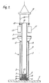
- FIGURE 1 shows a schematic cross-section through a first embodiment of apparatus in accordance with the invention at the start of an operation to form a stone column;
- FIGURE 2 shows schematically a second embodiment of apparatus in accordance with the invention;
- FIGURE 3 shows schematically a modification of the apparatus of Figure 2; and
- FIGURE 4 illustrates an alternative form of construction of the lowermost part of the apparatus shown in the other Figures.
- Referring to Figure 1 of the drawings, the apparatus indicated generally at 1 comprises an
inner tube 2 positioned coaxially within anouter tube 3. The lowermost end ofinner tube 2 is connected toouter tube 3 by means of a downwardly and outwardlyinclined wall portion 4. This extends around the entire periphery of inner tube 1 and, together with the lowermost portion 5 oftube 2 and thelowermost portion 6 oftube 3, defines a cavity comprising an upper, relatively narrowcylindrical portion 7; an intermediate,frustoconical portion 8; and a lower, relatively widecylindrical section 9. As shown in the drawing, the apparatus is placed over a heap ofstone 10 positioned on the ground 11. Theuppermost part 12 oftube 3 is connected totube 2 by awall portion 13.Wall 13 also carries a drivingplate 14 which extends abouttube 2 as shown. The drivingplate 14 can be carried by radial stiffeners welded both toplate 14 and to wallportion 13. Anextraction plate 15 is positioned about the uppermost region 16 oftube 2. Anannular hammer 17 is located between drivingplate 14 andextraction plate 15.Hammer 17 is suspended from a yoke 18 by suspending ropes 19 which pass through holes provided inextraction plate 15. - In use, the entire apparatus is suspended from a crane (not shown). Means for delivering stone (not shown) to the upper part 16 of
tube 2 is also provided. At the outset, with the apparatus positioned as shown,hammer 17 is used to drive the apparatus into the ground by repeated loads on drivingplate 14. When the apparatus has reached the required depth, delivery of stone to the interior oftube 2 is commenced and hammer 17 is used to withdraw the apparatus from the ground by repeated blows againstextraction plate 15. After each phase of extraction,hammer 17 is driven againstplate 14 so as to compact stone which has just been expelled fromlower end 6 of the apparatus. Thus hammer 17 alternately strikesextraction plate 15 and drivingplate 14 during the extract ion phase. The rate of delivery of stone may be selected so as to correspond with the average extraction rate of the apparatus. Stone delivery is stopped when thelower end 6 of the apparatus approaches ground level 11. At the end of a stone column-forming operation, the apparatus may be speedily removed to the next location at which a stone column is to be formed. - Referring now to Figure 2, an alternative embodiment of apparatus is illustra.ted in which the
outer tube 3 extends upwardly beyond theupper limit 20 ofinner tube 2. Theupper section 30 oftube 3 carries extraction lugs 31 and acylindrical driving plate 32, as well as alateral hopper 33 for feeding stone into the apparatus. Theregion 21 within theouter tube 3 above thelimit 20 ofinner tube 2 acts as a reservoir for stone which, in use, passes into the upper relativelynarrow portion 7 of the interior cavity and thence to thelower parts wall portion 30 to encourage free flow of stone downwardly through the apparatus. - Referring now to Figure 3, there is shown a modification of the apparatus in which the size of
reservoir 21 is much reduced, and in which the upper, relatively narrow portion of the cavity within theinner tube 2 comprises two sections - an upper, cylindrical section 7a occupying most of theregion 7 and a lower, downwardly and outwardly flared section 7b. The difference between the internal diameter, d, of theinner tube 2 and the diameter, D, of theouter tube 3 has been exaggerated for ease of depiction. - For successful operation, stone in the
regions hammer 17, so as to act as an arch of friction material located againstcross-wall 4 and bridging across the cavity at the level ofwall 4. Hence the ratio d/D must not be too large, and the mean diametrical dimension of the stone must not be too small relative to d. In one specific construction, of the type shown in Figure 3, the value of D was 570 mm and the value of d was 400 mm. Thetaper section 8 was 135 mm in vertical extent, and the secondary taper section 7b was 865 mm in vertical extent. Cylindrical section 7a was 2.5 m high. This apparatus worked extremely well in a series of tests using different stone, the mean diameter of the finest stone used being 25 mm and the mean diameter of the coarsest stone used being 100 mm. - Referring now to Figure 4, a modification of the lowermost part of the apparatus is illustrated. Here, the
wall 4 is directed radially outwardly between thetubes wide portion 9 to the first part 7b of the upper, relativelynarrow section 7. This arrangement is found to work satisfactorily because, it is believed, stone is trapped beneath thewall 4 and this assists in the formation of an arch when compaction forces are applied. The zone marked A and delineated by dashed lines represents the region beneathwall 4 where stone is friction-locked together.
Claims (10)
Priority Applications (1)
| Application Number | Priority Date | Filing Date | Title |
|---|---|---|---|
| AT85305321T ATE49430T1 (en) | 1984-07-25 | 1985-07-25 | GROUND TREATMENT. |
Applications Claiming Priority (2)
| Application Number | Priority Date | Filing Date | Title |
|---|---|---|---|
| GB848418991A GB8418991D0 (en) | 1984-07-25 | 1984-07-25 | Ground treatment |
| GB8418991 | 1984-07-25 |
Publications (3)
| Publication Number | Publication Date |
|---|---|
| EP0170503A2 true EP0170503A2 (en) | 1986-02-05 |
| EP0170503A3 EP0170503A3 (en) | 1986-12-30 |
| EP0170503B1 EP0170503B1 (en) | 1990-01-10 |
Family
ID=10564445
Family Applications (1)
| Application Number | Title | Priority Date | Filing Date |
|---|---|---|---|
| EP85305321A Expired - Lifetime EP0170503B1 (en) | 1984-07-25 | 1985-07-25 | Ground treatment |
Country Status (6)
| Country | Link |
|---|---|
| US (1) | US4730954A (en) |
| EP (1) | EP0170503B1 (en) |
| AT (1) | ATE49430T1 (en) |
| DE (1) | DE3575315D1 (en) |
| GB (1) | GB8418991D0 (en) |
| MY (1) | MY101133A (en) |
Cited By (10)
| Publication number | Priority date | Publication date | Assignee | Title |
|---|---|---|---|---|
| NL9200252A (en) * | 1992-02-12 | 1993-09-01 | Waal Technology & Consultancy | Foundation pile with widened root |
| US6168350B1 (en) | 1998-02-24 | 2001-01-02 | Kvaerner Cementation Foundations Ltd. | Method and apparatus for forming enlarged pile heads |
| DE4408173C2 (en) * | 1994-03-10 | 2002-04-18 | Moebius Josef Bau | Process for stabilizing the subsoil and for removing structural and traffic loads |
| DE10163237A1 (en) * | 2001-12-21 | 2003-07-10 | Franki Grundbau Gmbh | To place load-bearing piles in the ground, a tubular body with a closing point is shrouded by a geo-textile fabric, and driven into the ground, to be filled with a granular material and withdrawn leaving the compressed material as a pile |
| DE19518830B4 (en) * | 1994-03-10 | 2005-02-24 | Josef Möbius Bau-Gesellschaft (GmbH & Co.) | Method of stabilising underground below roads and buildings - involves column excavation replaced by geo-textile load-bearing casing for dewatering and compacting in-situ with resultant ground load absorption |
| DE19942016B4 (en) * | 1999-09-03 | 2006-01-05 | Franki Grundbau Gmbh | Apparatus and method for producing a soil column of viable granular filler material |
| EP2642031A1 (en) * | 2012-03-22 | 2013-09-25 | Keller Holding GmbH | Method of producing a protection assembly for protecting against tremors in the ground and device for same |
| CN103669349A (en) * | 2014-01-07 | 2014-03-26 | 方远建设集团股份有限公司 | Variable diameter stirring type anchor rod and construction method thereof |
| CN112227360A (en) * | 2020-09-25 | 2021-01-15 | 福建新华夏建工有限公司 | High-pulling-resistance-strength foundation reinforcing device for rotary jet drilling machine |
| CN113463628A (en) * | 2021-05-26 | 2021-10-01 | 中海石油(中国)有限公司 | Construction method for stably puncturing pile shoe of self-elevating platform |
Families Citing this family (20)
| Publication number | Priority date | Publication date | Assignee | Title |
|---|---|---|---|---|
| US5256003A (en) * | 1989-12-26 | 1993-10-26 | Konoike Construction Co., Ltd. | Method for automatically driving gravel drain piles and execution apparatus therefor |
| US5279502A (en) * | 1991-10-24 | 1994-01-18 | Geotechnics America, Inc. | Apparatus and method for constructing compacted granular or stone columns in soil masses |
| US5549168A (en) * | 1995-02-06 | 1996-08-27 | Mgf Maschinen- Und Geraete-Fabrik Gmbh | Pile driving apparatus |
| EP0811723B1 (en) * | 1996-05-31 | 2001-01-03 | Wilhelm Hess | Support for trench shoring device |
| US6030150A (en) | 1998-02-25 | 2000-02-29 | Dana A. Schmednecht | Method and apparatus for constructing subterranean walls comprised of granular material |
| DE19814021A1 (en) * | 1998-03-30 | 1999-10-14 | Degen Wilhelm | Device for introducing a foreign substance into soils or for compacting the soil |
| US6354766B1 (en) * | 1999-02-09 | 2002-03-12 | Geotechnical Reinforcement Company, Inc. | Methods for forming a short aggregate pier and a product formed from said methods |
| US6425713B2 (en) * | 2000-06-15 | 2002-07-30 | Geotechnical Reinforcement Company, Inc. | Lateral displacement pier, and apparatus and method of forming the same |
| US9169611B2 (en) | 2000-06-15 | 2015-10-27 | Geopier Foundation Company, Inc. | Method and apparatus for building support piers from one or more successive lifts formed in a soil matrix |
| DE102005001227A1 (en) * | 2005-01-10 | 2006-07-20 | Keller Grundbau Gmbh | Method for improving a foundation in the ground comprises inserting columns having a lower bound section made from mortar or cement and an upper bound section made from ballast |
| US7726913B1 (en) | 2007-08-15 | 2010-06-01 | David Sjogren | Method and apparatus for forming in ground piles |
| US8562258B2 (en) | 2008-07-29 | 2013-10-22 | Geopier Foundation Company, Inc. | Shielded tamper and method of use for making aggregate columns |
| MX2011000815A (en) * | 2008-07-29 | 2011-05-30 | Geopier Foundation Co Inc | Shielded tamper and method of use for making aggregate columns. |
| US9637882B2 (en) | 2009-09-03 | 2017-05-02 | Geopier Foundation Company, Inc. | Method and apparatus for making an expanded base pier |
| US20110052330A1 (en) * | 2009-09-03 | 2011-03-03 | Geopier Foundation Company, Inc. | Method and Apparatus for Making an Expanded Base Pier |
| FR2960571B1 (en) * | 2010-05-27 | 2012-06-22 | Soletanche Freyssinet | MACHINE AND METHOD FOR PRODUCING COLUMNS IN A SOIL |
| JP6667276B2 (en) * | 2015-12-04 | 2020-03-18 | 日本製鉄株式会社 | Crushed stone pile construction method, crushed stone pile construction jig, and crushed stone pile construction system |
| JP6707778B2 (en) * | 2016-02-26 | 2020-06-10 | 大西 正人 | Excavation member and ground improvement method using the same |
| JP6985948B2 (en) * | 2018-02-02 | 2021-12-22 | 五洋建設株式会社 | Measurement device for CP method, casing pipe for CP method and construction management method for CP method |
| CN112323876A (en) * | 2020-11-03 | 2021-02-05 | 北京顺义建筑企业集团公司 | Method for detecting pile end resistance of pile formed by holding-pressure type hammering and pressure grouting by small-area method |
Citations (5)
| Publication number | Priority date | Publication date | Assignee | Title |
|---|---|---|---|---|
| US1887630A (en) * | 1927-11-15 | 1932-11-15 | Frankignoul Pieux Armes | Method and device for the production of piles of concrete and the like |
| GB664854A (en) * | 1948-10-21 | 1952-01-16 | Svenska Entreprenad Aktiebolag | A method and an equipment for the making of piles of concrete in situ |
| CH350934A (en) * | 1957-05-20 | 1960-12-15 | Eggstein Julius | Method and device for the production of in-situ concrete piles |
| GB1133952A (en) * | 1965-10-09 | 1968-11-20 | Monk & Company Ltd A | Improvements in or relating to the installation of sand drains |
| GB1430159A (en) * | 1973-04-18 | 1976-03-31 | Cook P M | Apparatus for driving tubes into the ground |
Family Cites Families (4)
| Publication number | Priority date | Publication date | Assignee | Title |
|---|---|---|---|---|
| US2649694A (en) * | 1948-07-27 | 1953-08-25 | Frankignoul Pieux Armes | Method and device for driving tubular bodies into the ground by means of fluid jets |
| US3406524A (en) * | 1967-05-03 | 1968-10-22 | Pan American Petroleum Corp | Fluid-sonic pile driving |
| US4384809A (en) * | 1980-07-22 | 1983-05-24 | Fredric Rusche | Mandrel closure and process for in situ pile formation |
| CH651340A5 (en) * | 1982-12-06 | 1985-09-13 | Claudio Guandalini | DEVICE AND PROCEDURE FOR PILEING LANDS REALIZING REINFORCED CONCRETE POLES WITHOUT COATING. |
-
1984
- 1984-07-25 GB GB848418991A patent/GB8418991D0/en active Pending
-
1985
- 1985-07-25 DE DE8585305321T patent/DE3575315D1/en not_active Expired - Lifetime
- 1985-07-25 AT AT85305321T patent/ATE49430T1/en not_active IP Right Cessation
- 1985-07-25 EP EP85305321A patent/EP0170503B1/en not_active Expired - Lifetime
-
1986
- 1986-10-02 US US06/914,378 patent/US4730954A/en not_active Expired - Fee Related
-
1987
- 1987-01-07 MY MYPI87000018A patent/MY101133A/en unknown
Patent Citations (5)
| Publication number | Priority date | Publication date | Assignee | Title |
|---|---|---|---|---|
| US1887630A (en) * | 1927-11-15 | 1932-11-15 | Frankignoul Pieux Armes | Method and device for the production of piles of concrete and the like |
| GB664854A (en) * | 1948-10-21 | 1952-01-16 | Svenska Entreprenad Aktiebolag | A method and an equipment for the making of piles of concrete in situ |
| CH350934A (en) * | 1957-05-20 | 1960-12-15 | Eggstein Julius | Method and device for the production of in-situ concrete piles |
| GB1133952A (en) * | 1965-10-09 | 1968-11-20 | Monk & Company Ltd A | Improvements in or relating to the installation of sand drains |
| GB1430159A (en) * | 1973-04-18 | 1976-03-31 | Cook P M | Apparatus for driving tubes into the ground |
Cited By (13)
| Publication number | Priority date | Publication date | Assignee | Title |
|---|---|---|---|---|
| NL9200252A (en) * | 1992-02-12 | 1993-09-01 | Waal Technology & Consultancy | Foundation pile with widened root |
| DE4408173C5 (en) * | 1994-03-10 | 2006-04-27 | Josef Möbius Bau-Gesellschaft (GmbH & Co.) | Method of stabilizing the substrate and removing structural and traffic loads |
| DE4408173C2 (en) * | 1994-03-10 | 2002-04-18 | Moebius Josef Bau | Process for stabilizing the subsoil and for removing structural and traffic loads |
| DE19518830B4 (en) * | 1994-03-10 | 2005-02-24 | Josef Möbius Bau-Gesellschaft (GmbH & Co.) | Method of stabilising underground below roads and buildings - involves column excavation replaced by geo-textile load-bearing casing for dewatering and compacting in-situ with resultant ground load absorption |
| US6168350B1 (en) | 1998-02-24 | 2001-01-02 | Kvaerner Cementation Foundations Ltd. | Method and apparatus for forming enlarged pile heads |
| DE19942016B4 (en) * | 1999-09-03 | 2006-01-05 | Franki Grundbau Gmbh | Apparatus and method for producing a soil column of viable granular filler material |
| DE10163237A1 (en) * | 2001-12-21 | 2003-07-10 | Franki Grundbau Gmbh | To place load-bearing piles in the ground, a tubular body with a closing point is shrouded by a geo-textile fabric, and driven into the ground, to be filled with a granular material and withdrawn leaving the compressed material as a pile |
| EP2642031A1 (en) * | 2012-03-22 | 2013-09-25 | Keller Holding GmbH | Method of producing a protection assembly for protecting against tremors in the ground and device for same |
| CN103669349A (en) * | 2014-01-07 | 2014-03-26 | 方远建设集团股份有限公司 | Variable diameter stirring type anchor rod and construction method thereof |
| CN112227360A (en) * | 2020-09-25 | 2021-01-15 | 福建新华夏建工有限公司 | High-pulling-resistance-strength foundation reinforcing device for rotary jet drilling machine |
| CN112227360B (en) * | 2020-09-25 | 2021-10-29 | 福建新华夏建工有限公司 | High-pulling-resistance-strength foundation reinforcing device for rotary jet drilling machine |
| CN113463628A (en) * | 2021-05-26 | 2021-10-01 | 中海石油(中国)有限公司 | Construction method for stably puncturing pile shoe of self-elevating platform |
| CN113463628B (en) * | 2021-05-26 | 2022-06-07 | 中海石油(中国)有限公司 | Construction method for stably puncturing pile shoe of self-elevating platform |
Also Published As
| Publication number | Publication date |
|---|---|
| MY101133A (en) | 1991-07-31 |
| ATE49430T1 (en) | 1990-01-15 |
| EP0170503A3 (en) | 1986-12-30 |
| GB8418991D0 (en) | 1984-08-30 |
| EP0170503B1 (en) | 1990-01-10 |
| US4730954A (en) | 1988-03-15 |
| DE3575315D1 (en) | 1990-02-15 |
Similar Documents
| Publication | Publication Date | Title |
|---|---|---|
| EP0170503B1 (en) | Ground treatment | |
| EP1888848B1 (en) | Slotted mandrel for lateral displacement pier and method of use | |
| KR100968656B1 (en) | Apparatus and method for forming compacted piers with multiple lifts | |
| US7326004B2 (en) | Apparatus for providing a rammed aggregate pier | |
| US4397588A (en) | Method of constructing a compacted granular or stone column in soil masses and apparatus therefor | |
| US8221034B2 (en) | Methods of providing a support column | |
| US9243379B2 (en) | Method of providing a support column | |
| US4230425A (en) | Method and installation for producing cast-in-situ piles | |
| US20210164185A1 (en) | Methods and apparatuses for compacting soil and granular materials | |
| US4619558A (en) | Apparatus for producing in-situ concreted piles with enlarged bases | |
| EP3041998B1 (en) | Methods and apparatuses for compacting soil and granular materials | |
| EP0084921B1 (en) | Piles | |
| EP0519575A1 (en) | Method of making a foundation pile | |
| RU2266368C2 (en) | Method for cast-in-place pile building in collapsible ground | |
| WO1994017252A1 (en) | Improvements in or relating to foundations | |
| US20240026625A1 (en) | Methods and apparatuses for compacting soil and granular materials | |
| KR960003748B1 (en) | Working method of concrete pile or sand pile for a soft-soil foundation | |
| KR900005913B1 (en) | Base stake inflated in bump state at lower end there of and its construction | |
| CN1035205C (en) | Job practice of prefabricated pile | |
| HU193331B (en) | Method for getting the prefabricated bearing pile into soil |
Legal Events
| Date | Code | Title | Description |
|---|---|---|---|
| PUAI | Public reference made under article 153(3) epc to a published international application that has entered the european phase |
Free format text: ORIGINAL CODE: 0009012 |
|
| AK | Designated contracting states |
Kind code of ref document: A2 Designated state(s): AT BE CH DE FR GB IT LI LU NL SE |
|
| PUAL | Search report despatched |
Free format text: ORIGINAL CODE: 0009013 |
|
| AK | Designated contracting states |
Kind code of ref document: A3 Designated state(s): AT BE CH DE FR GB IT LI LU NL SE |
|
| 17P | Request for examination filed |
Effective date: 19870519 |
|
| 17Q | First examination report despatched |
Effective date: 19881125 |
|
| GRAA | (expected) grant |
Free format text: ORIGINAL CODE: 0009210 |
|
| AK | Designated contracting states |
Kind code of ref document: B1 Designated state(s): AT BE CH DE FR GB IT LI LU NL SE |
|
| PG25 | Lapsed in a contracting state [announced via postgrant information from national office to epo] |
Ref country code: SE Effective date: 19900110 Ref country code: LI Effective date: 19900110 Ref country code: CH Effective date: 19900110 Ref country code: AT Effective date: 19900110 |
|
| REF | Corresponds to: |
Ref document number: 49430 Country of ref document: AT Date of ref document: 19900115 Kind code of ref document: T |
|
| ITF | It: translation for a ep patent filed |
Owner name: JACOBACCI & PERANI S.P.A. |
|
| REF | Corresponds to: |
Ref document number: 3575315 Country of ref document: DE Date of ref document: 19900215 |
|
| ET | Fr: translation filed | ||
| REG | Reference to a national code |
Ref country code: CH Ref legal event code: PL |
|
| PLBE | No opposition filed within time limit |
Free format text: ORIGINAL CODE: 0009261 |
|
| STAA | Information on the status of an ep patent application or granted ep patent |
Free format text: STATUS: NO OPPOSITION FILED WITHIN TIME LIMIT |
|
| 26N | No opposition filed | ||
| PGFP | Annual fee paid to national office [announced via postgrant information from national office to epo] |
Ref country code: GB Payment date: 19920501 Year of fee payment: 8 |
|
| PGFP | Annual fee paid to national office [announced via postgrant information from national office to epo] |
Ref country code: FR Payment date: 19920505 Year of fee payment: 8 |
|
| PGFP | Annual fee paid to national office [announced via postgrant information from national office to epo] |
Ref country code: LU Payment date: 19920520 Year of fee payment: 8 |
|
| PGFP | Annual fee paid to national office [announced via postgrant information from national office to epo] |
Ref country code: BE Payment date: 19920604 Year of fee payment: 8 |
|
| PGFP | Annual fee paid to national office [announced via postgrant information from national office to epo] |
Ref country code: DE Payment date: 19920707 Year of fee payment: 8 |
|
| ITTA | It: last paid annual fee | ||
| PGFP | Annual fee paid to national office [announced via postgrant information from national office to epo] |
Ref country code: NL Payment date: 19920731 Year of fee payment: 8 |
|
| EPTA | Lu: last paid annual fee | ||
| PG25 | Lapsed in a contracting state [announced via postgrant information from national office to epo] |
Ref country code: LU Free format text: LAPSE BECAUSE OF NON-PAYMENT OF DUE FEES Effective date: 19930725 Ref country code: GB Effective date: 19930725 |
|
| PG25 | Lapsed in a contracting state [announced via postgrant information from national office to epo] |
Ref country code: BE Effective date: 19930731 |
|
| BERE | Be: lapsed |
Owner name: CEMENTATION PILING & FOUNDATIONS LTD Effective date: 19930731 |
|
| PG25 | Lapsed in a contracting state [announced via postgrant information from national office to epo] |
Ref country code: NL Effective date: 19940201 |
|
| NLV4 | Nl: lapsed or anulled due to non-payment of the annual fee | ||
| GBPC | Gb: european patent ceased through non-payment of renewal fee |
Effective date: 19930725 |
|
| PG25 | Lapsed in a contracting state [announced via postgrant information from national office to epo] |
Ref country code: FR Effective date: 19940331 |
|
| PG25 | Lapsed in a contracting state [announced via postgrant information from national office to epo] |
Ref country code: DE Effective date: 19940401 |
|
| REG | Reference to a national code |
Ref country code: FR Ref legal event code: ST |