EP0170497B1 - Beer container having means for frothing the content thereof - Google Patents
Beer container having means for frothing the content thereof Download PDFInfo
- Publication number
- EP0170497B1 EP0170497B1 EP85305280A EP85305280A EP0170497B1 EP 0170497 B1 EP0170497 B1 EP 0170497B1 EP 85305280 A EP85305280 A EP 85305280A EP 85305280 A EP85305280 A EP 85305280A EP 0170497 B1 EP0170497 B1 EP 0170497B1
- Authority
- EP
- European Patent Office
- Prior art keywords
- container
- beer
- wall
- movable member
- mounting member
- Prior art date
- Legal status (The legal status is an assumption and is not a legal conclusion. Google has not performed a legal analysis and makes no representation as to the accuracy of the status listed.)
- Expired
Links
Images





Classifications
-
- B—PERFORMING OPERATIONS; TRANSPORTING
- B65—CONVEYING; PACKING; STORING; HANDLING THIN OR FILAMENTARY MATERIAL
- B65D—CONTAINERS FOR STORAGE OR TRANSPORT OF ARTICLES OR MATERIALS, e.g. BAGS, BARRELS, BOTTLES, BOXES, CANS, CARTONS, CRATES, DRUMS, JARS, TANKS, HOPPERS, FORWARDING CONTAINERS; ACCESSORIES, CLOSURES, OR FITTINGS THEREFOR; PACKAGING ELEMENTS; PACKAGES
- B65D85/00—Containers, packaging elements or packages, specially adapted for particular articles or materials
- B65D85/70—Containers, packaging elements or packages, specially adapted for particular articles or materials for materials not otherwise provided for
- B65D85/72—Containers, packaging elements or packages, specially adapted for particular articles or materials for materials not otherwise provided for for edible or potable liquids, semiliquids, or plastic or pasty materials
- B65D85/73—Containers, packaging elements or packages, specially adapted for particular articles or materials for materials not otherwise provided for for edible or potable liquids, semiliquids, or plastic or pasty materials with means specially adapted for effervescing the liquids, e.g. for forming bubbles or beer head
-
- A—HUMAN NECESSITIES
- A47—FURNITURE; DOMESTIC ARTICLES OR APPLIANCES; COFFEE MILLS; SPICE MILLS; SUCTION CLEANERS IN GENERAL
- A47G—HOUSEHOLD OR TABLE EQUIPMENT
- A47G19/00—Table service
- A47G19/22—Drinking vessels or saucers used for table service
- A47G19/2205—Drinking glasses or vessels
- A47G19/2227—Drinking glasses or vessels with means for amusing or giving information to the user
- A47G19/2233—Drinking glasses or vessels with means for amusing or giving information to the user related to the evolution of bubbles in carbonated beverages
-
- Y—GENERAL TAGGING OF NEW TECHNOLOGICAL DEVELOPMENTS; GENERAL TAGGING OF CROSS-SECTIONAL TECHNOLOGIES SPANNING OVER SEVERAL SECTIONS OF THE IPC; TECHNICAL SUBJECTS COVERED BY FORMER USPC CROSS-REFERENCE ART COLLECTIONS [XRACs] AND DIGESTS
- Y10—TECHNICAL SUBJECTS COVERED BY FORMER USPC
- Y10S—TECHNICAL SUBJECTS COVERED BY FORMER USPC CROSS-REFERENCE ART COLLECTIONS [XRACs] AND DIGESTS
- Y10S220/00—Receptacles
- Y10S220/906—Beverage can, i.e. beer, soda
Definitions
- the present invention relates to a beer container, such as a can or bottle, utilized for direct drinking of the content, i.e., the beer being drunk directly from the container without being transferred to a receptacle such as a mug. More specifically, it relates to such a container having means for frothing the content thereof just before drinking same.
- a creamy layer of microfroth on the surface of beer just before drinking the beer, as such a layer improves the taste of the beer.
- a high pressure gas such as carbonic acid gas
- a layer of froth having a good body is formed on the surface of the beer. This layer is formed because carbon dioxide dissolved in a saturated state in the beer accommodated in the barrel, under a high pressure of 2 to 3 kg/cm 2 , is rapidly gasified by the mechanical impetus imparted on the outflowing beer stream.
- a means for facilitating the -gasification of carbon dioxide dissolved in the beer by pouring the beer from a container into a mug through a tap having a main supply opening and at least an auxiliary opening, whereby the beer stream poured from the auxiliary opening taps upon the surface of the poured beer in the mug, which generates vibration and forms a flock of micro- froth on the surface of the beer in a mug.
- the froth flock is moved to and fro by a beer stream poured from the main supply opening and forms a creamy layer on the entire surface of the beer.
- JP-A-57-28797 a means is proposed for forming a froth layer, comprising a tap for a container having an air inlet pipe designed to have a proper inner diameter and length so as to impart a pulsative movement to an outflowing stream of beer.
- FR-A-2364623 (equivalent to GB-A-1588624) suggests frothing stout by imparting ultrasonic vibration either to a bottle or can from which the stout is then poured, or to a glass into which it has been poured. The vibration is caused by resting the vessel on an ultrasonic vibration tray.
- a primary object of the present invention to provide a container of beer in which a creamy micro-froth layer can be formed on the surface of beer without utilizing a pressurized gas or a dispenser, the froth layer being similar to the froth layer of a draft beer poured from a large size barrel utilizing a pressurized gas.
- the movable member of the vibrating means may be constituted in a form of an ear utilized as a handle of the container.
- the most preferable vibrating means is that according to claim 10 of the present invention.
- a profile of the projection to be in contact with the bottom wall of the container is so designed that when the container is struck thereby no deformation is imparted to the bottom wall of the container and the maximum width of the contacting area is sufficiently smaller in relation to a wavelength of a vibration propagated in the wall of the container due to the striking of the container thereby.
- the projections are preferably arranged at a distance of more than 3 mm from each other.
- the mounting member of the vibrating means is preferably constituted by a disc having a convex upper and/or lower surface complementary to that of the bottom wall of the container, and the movable member preferably comprises an annular ring encircling the mounting member.
- Both members may be connected to each other by a bridge member provided between confronting parts of the peripheries of both members.
- the projection is arranged in upper and/or lower surfaces of the free end portion of the movable member, which portion corresponds to a part positioned diametrically opposite to the bridge member.
- the upper and/or lower surfaces of the mounting member may preferably be roughened to provide a desirable bonding effect when the mounting member is to be adhered to the bottom wall of the container.
- the roughened surface may be formed of a plurality of ribs.
- the ribs may be arranged in parallel, in a lattice form, radially or concentrically.
- the vibrating means preferably may be of a symmetric form relative to an imaginary plane dividing the upper and lower parts of the vibrating means.
- the present invention comprises a mounting member to be attached to the bottom wall of a container, a first movable member encircling the mounting member and a second movable member encircling the first movable member.
- the mounting member is resiliently connected to the first mounting member at a part of the periphery thereof with a first bridge member and the second movable member is resiliently connected to the first movable member at a part of the periphery thereof with a second bridge member, which part is disposed at a position diametrically opposite to the first bridge member.
- At least one projection is provided on either side of the first movable member in the vicinity of the second bridge member and/or on either side of the second bridge member along the entire periphery thereof.
- the vibrating means comprises an annular-shaped mounting member to be attached to the bottom wall of a container and a bar- shaped movable member resiliently connected, at an end thereof, to the mounting member and diametrically extending inward therefrom so as to form a free end provided with at least one projection on that free end.
- a layer of fine creamy froth can be obtained on the surface of beer by imparting a localized fine vibration to at least a part of a wall of a container of beer.
- the above part of a wall may be any portion of the container with which the beer accommodated therein is in contact, such as side or bottom wall of the container.
- the most preferable portions are the center of the bottom wall and the lower area of the side wall close to the bottom wall.
- Localized vibration as used herein means a vibration limited to a narrow area in the vicinity of a position where the vibration has been initiated and, therefore, does not include a natural vibration occurring throughout the entire body of the container.
- fine vibration denotes vibration having a frequency higher than the natural frequency of the container.
- a rubber string 5 encircles a side wall 2 of a can 1 in which beer 4 is accommodated.
- a small piece 6 of a hard material such as hard plastic is secured to a part of the rubber string 5. After the can 1 has been opened, the piece 6 is picked up by fingers, pulled together with the rubber string 5 away from a surface of the side wall 2 and then released so that the piece 6 is made to strike the surface of the side wall 2 of the can 1 by the return force of the rubber string 5.
- a vibration is generated at the struck point of the side wall 2 and is propagated radially therefrom to the surrounding area, causing an amount of microfroth 7 to be generated in the beer.
- This microfroth 7 is generated first at the point struck and then over a wider area adjacent thereto. This froth 7 rises to and forms a creamy layer on the surface of the beer 4, as illustrated in Fig. 2.
- the froth 7 is formed of carbonic acid gas dissolving in the beer which tends to be gasified by a mechanical stimulation imparted thereto in accordance with the following mechanism:
- the vibration is transmitted not only to the surrounding wall 2 of the can 1 as stated above but also to the beer 4 itself, in which it is propagated as a wave of condensation and rarefaction. Therefore, the froth 7 rises throughout the body of the beer 4 at the final stage.
- the strike may be imparted to the bottom wall 3 of the can instead of the side wall 2 as stated above.
- a first embodiment of the can 1 shown in Fig. 3 is provided with a vibrating means 10 made of metal on the bottom wall 3 of the can 1.
- the vibrating means 10 comprises a mounting member 11 and a bar-like movable member 12 extending from the mounting member 11 and having a free end 13 to which a striking head 14 is secured.
- the movable member 12 is resiliently connected to the mounting member 11 which is fixed to the bottom wall 3 of the can 1, as shown in Fig. 4. In use, the free end 13 of the movable member 12 is resiliently lifted away from the bottom wall 3 by the fingers and then released so that the striking head 14 strikes the bottom wall 3.
- froth is generated not only at a point struck by the striking head 14 but also at the position corresponding to the mounting member 11, because the vibration of the movable member itself is transmitted to the bottom wall 3 through the mounting member 11. Accordingly, it is possible to eliminate the striking head 14 if the free vibration of the movable member 12 lasts longer.
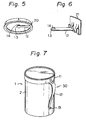
- the vibrating means 10 may be mounted on the bottom wall 3 by means of a mounting ring 20, as illustrated in Fig. 5, or a hook member 21 as illustrated in Fig. 6.
- the vibrating means 10 is secured to the side wall 2 of the can 1, it is preferably in the form of an ear 30 of the can 1 as shown in Fig. 7.
- This means is fitted on the periphery of the can 1 by a mounting ring 11.
- the ear 30 constitutes the movable member 12 of Figs 3 through 6 and also serves as a handle for holding the can 1 when drinking the beer.
- a vibrating means 40 is shown in Figs. 8 through 11, which is improved by taking the actual inustrial manufacturing process into account. That is, according to this aspect, the vibrating means can be manufactured utilizing a reduced amount of plastic material and the mounting thereof to the can can be easily automated.
- a can 41 used for this embodiment is preferably of such a type that a lid thereof can be removed entirely from the container body before drinking the beer and a bottom wall 43 thereof is concaven inwardly as usual.
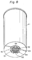
- the vibrating member 40 is attached to the bottom wall 43 as illustrated in Fig. 8.
- the vibrating means 40 is preferably made of an elastic material such as a metal or hard plastic and comprises a disc-like mounting member 51 and a movable member 52 having an annular shape and concentrically encircling the mounting member 51.
- the members 51 and 52 are connected to each other by a bridge member 56 at a part of the peripheries thereof.
- the mounting member 51 is fixed on the center of the bottom wall 43 of the can 41 in a known manner, such as by an adhesive or by welding.
- the movable member 52 is able to resiliently move up and down in a hinge fashion about the bridge member 56 as both members 51, 52 are resiliently bent by a force applied perpendicularly to a free end 53 of the movable member 52 disposed diametrically opposite to the bridge member 56, as illustrated in dotted lines in Fig. 10.
- the free end 53 of the movable member 52 is displaceable relative to.the bottom wall 43.
- a plurality of projections 54 are formed as a striking head on at least a surface of the movable member 52 confronting the bottom wall 43.
- the free end 53 of the movable member 52 is lifted up by the fingers and quickly released.
- the projections 54 then strike the bottom wall 43 as stated before.
- the curvature of the surface of the mounting member 51 to be fixed on the bottom wall 43 of the can 41 is matched with that of the bottom wall 43 so that the mating surfaces are in tight contact, as shown in Fig. 11.
- the shape of the vibrating means 40 is symmetrical relative to a center plane x-x of Fig. 11. This facilitates the ease of positioning of the vibrating means 40 in place on the bottom wall 43 when the former is randomly fed onto the latter in the automated assembly line of the can, i.e., it can naturally occupy a central position of the bottom wall 43 and causes no problem even if it is upside down.
- the mounting member 51 comprises a base 57 having a disc shape, both sides of which have a center rib 58 and a plurality of parallel lateral ribs 59 orthogonal to the center rib 58, as illustrated in Figs. 9 and 11.
- the outer edges of the ribs 58, 59 are tapered to form a substantially convex contacting surface complementary to the bottom wall 43, as stated before.
- an adhesive 55 such as a hot melt resin deposited on the bottom wall 43 can extensively invade the cavities between the ribs and, therefore, produce a desirable fixation of the vibrating means.
- the ribs 58, 59 may be arranged in a different manner, such as lattice form, concentric form, or radial form as illustrated in Figs. 12 through 14.
- the contacting surface need not be constructed with ribs, provided that a roughened surface suitable for fixation to the can's wall is obtainable, such as by notches or the like.
- FIG. 15 is a graph illustrating the degree of the generation of the microfroth in relation to a cross sectional profile of the projection 54.
- the experiment was carried out under conditions wherein the temperature of the beer was 8°C and the temperature of the air was 21°C and four vibrating means were utilized, each of which was substantially identical to that described above but having a different projection profile, as shown in Fig. 16(a) through (d), and was secured on the bottom wall 43 of the respective can 41.
- the ordinate of the graph represents a height of a microfroth layer on the beer surface generated by the strike and the abscissa thereof shows the number of strikes.
- the projection having a semispherical profile (d) was the most effective and that having a conical profile the most inferior.
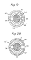
- FIG. 19 Another version of preferable vibrating means 50 is shown in Fig. 19.
- a second annular movable member 62 is added to the vibrating means 40 shown in Figs. 8 through 11.
- the second movable member 62 encircles the first movable member 52 and is resiliently connected thereto by a second bridge member 66 at a part of its periphery diametrically opposite to the first bridge member 56.
- the remaining structure thereof is identical to that of the vibrating means 40 of Fig. 9.
- the striking action can be performed even without looking, simply by picking up any part of the second movable member 62.
- This aspect may be modified as shown in Fig. 20, which has a plurality of projections 54 all around the periphery of the second movable member 62 instead of on the specified area of the first movable member 52.
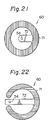
- a movable member 72 is disposed at the inside of the vibrating means and a mounting member 71 encircles the movable member 72.
- a can of beer or a vibrating means thereof is provided, which enables the user to form a layer of microfroth on a surface of the beer contained therein whenever the user wants to drink the beer.
- a specific form of the vibrating means enables automation of the assembly system of the can.
- the vibrating means according to the present invention can be made in one piece from a hard plastic such as polyethylene orABS resin through a conventional molding method at a low cost.
Landscapes
- Engineering & Computer Science (AREA)
- Mechanical Engineering (AREA)
- Details Of Rigid Or Semi-Rigid Containers (AREA)
- Table Devices Or Equipment (AREA)
Description
- The present invention relates to a beer container, such as a can or bottle, utilized for direct drinking of the content, i.e., the beer being drunk directly from the container without being transferred to a receptacle such as a mug. More specifically, it relates to such a container having means for frothing the content thereof just before drinking same.
- It is well known that it is preferable to form a creamy layer of microfroth on the surface of beer just before drinking the beer, as such a layer improves the taste of the beer. Generally speaking, when beer is forcibly poured into a mug from a large size barrel, having a content of, for example, 25 liters or 10 liters, by utilizing a high pressure gas, such as carbonic acid gas, a layer of froth having a good body is formed on the surface of the beer. This layer is formed because carbon dioxide dissolved in a saturated state in the beer accommodated in the barrel, under a high pressure of 2 to 3 kg/cm2, is rapidly gasified by the mechanical impetus imparted on the outflowing beer stream. Contrary to this, in the case of a medium size can suitable for home use or personal use made from a metal or plastic and having a content of, for example, 2 or 3 liters, the beer contained therein is usually completely consumed without necessity to consider restoring a residual content. Therefore, since a high pressure gas is not necessarily used when pouring the beer out of the container, gasification of the supersaturated carbon dioxide becomes relatively poor.
- Many proposals have been made for forming a micro-froth layer on the surface of beer accommodated in a medium size container prior to drinking. For example, in JP-A-56-74487, a means is provided for facilitating the -gasification of carbon dioxide dissolved in the beer by pouring the beer from a container into a mug through a tap having a main supply opening and at least an auxiliary opening, whereby the beer stream poured from the auxiliary opening taps upon the surface of the poured beer in the mug, which generates vibration and forms a flock of micro- froth on the surface of the beer in a mug. The froth flock is moved to and fro by a beer stream poured from the main supply opening and forms a creamy layer on the entire surface of the beer.
- In JP-A-57-28797, a means is proposed for forming a froth layer, comprising a tap for a container having an air inlet pipe designed to have a proper inner diameter and length so as to impart a pulsative movement to an outflowing stream of beer.
- The above-mentioned means, however, are effective only for a relatively large size container from which the beer therein is poured into a mug for drinking. Accordingly, these prior arts are not suitable for the purpose of the present invention, in which the beer is drunk directly from the container after a lid thereof has been opened.
- FR-A-2364623 (equivalent to GB-A-1588624) suggests frothing stout by imparting ultrasonic vibration either to a bottle or can from which the stout is then poured, or to a glass into which it has been poured. The vibration is caused by resting the vessel on an ultrasonic vibration tray.
- Thus, it is a primary object of the present invention to provide a container of beer in which a creamy micro-froth layer can be formed on the surface of beer without utilizing a pressurized gas or a dispenser, the froth layer being similar to the froth layer of a draft beer poured from a large size barrel utilizing a pressurized gas.
- It is a second object of the invention to provide a means for forming a creamy micro-froth layer on the surface of beer in a container, this means being utilized together with the container.
- The above object of the present invention is achieved by a container of beer according to
claim 1. - The movable member of the vibrating means may be constituted in a form of an ear utilized as a handle of the container.
- The most preferable vibrating means is that according to claim 10 of the present invention. A profile of the projection to be in contact with the bottom wall of the container is so designed that when the container is struck thereby no deformation is imparted to the bottom wall of the container and the maximum width of the contacting area is sufficiently smaller in relation to a wavelength of a vibration propagated in the wall of the container due to the striking of the container thereby.
- If more than one projection is used, the projections are preferably arranged at a distance of more than 3 mm from each other.
- The mounting member of the vibrating means is preferably constituted by a disc having a convex upper and/or lower surface complementary to that of the bottom wall of the container, and the movable member preferably comprises an annular ring encircling the mounting member. Both members may be connected to each other by a bridge member provided between confronting parts of the peripheries of both members. The projection is arranged in upper and/or lower surfaces of the free end portion of the movable member, which portion corresponds to a part positioned diametrically opposite to the bridge member.
- The upper and/or lower surfaces of the mounting member may preferably be roughened to provide a desirable bonding effect when the mounting member is to be adhered to the bottom wall of the container. Further, the roughened surface may be formed of a plurality of ribs. The ribs may be arranged in parallel, in a lattice form, radially or concentrically.
- The vibrating means preferably may be of a symmetric form relative to an imaginary plane dividing the upper and lower parts of the vibrating means.
- Another aspect of the vibrating means is provided by the present invention, which comprises a mounting member to be attached to the bottom wall of a container, a first movable member encircling the mounting member and a second movable member encircling the first movable member. The mounting member is resiliently connected to the first mounting member at a part of the periphery thereof with a first bridge member and the second movable member is resiliently connected to the first movable member at a part of the periphery thereof with a second bridge member, which part is disposed at a position diametrically opposite to the first bridge member. At least one projection is provided on either side of the first movable member in the vicinity of the second bridge member and/or on either side of the second bridge member along the entire periphery thereof.
- According to a further aspect of the present invention, the vibrating means comprises an annular-shaped mounting member to be attached to the bottom wall of a container and a bar- shaped movable member resiliently connected, at an end thereof, to the mounting member and diametrically extending inward therefrom so as to form a free end provided with at least one projection on that free end.
- The other objects and advantages of the present invention will be apparent from the description of the preferred embodiments of the present invention with reference to the accompanying drawings: wherein
- Figs. 1 and 2 are perspective views of a can of beer illustrating a principle of the present invention;
- Fig. 3 illustrates a perspective view of a first embodiment of a can according to the present invention;
- Fig. 4 illustrates a side sectional view of the can shown in Fig. 3;
- Fig. 5 illustrates a perspective view of another embodiment of a vibrating means according to the present invention;
- Fig. 6 illustrates a perspective view of a further embodiment of a vibrating means according to the present invention;
- Fig. 7 illustrates a perspective view of a can having vibrating means in the form of an ear, according to the present invention;
- Fig. 8 illustrates a perspective view of a can provided with a first embodiment of the most preferable vibrating means;
- Figs. 9 and 10 illustrate a plan view and a side view, respectively, of the vibrating means shown in Fig. 8;
- Fig. 11 is a side sectional view of the lower part of the can shown in Fig. 8, illustrating a cross section of the vibrating means taken along the line Y-Y in Fig. 9;
- Figs. 12 through 14 illustrate further embodiments of the vibrating means shown in Figs. 8 through 11;
- Fig. 15 is a graph illustrating the effect of cross sections of a projection having different shapes on frothing;
- Fig. 16 illustrates various cross sectional profiles of the projections in Fig. 15;
- Fig. 17 is a plan view of a vibrating means utilized in the frothing experiment;
- Fig. 18 is a graph illustrating the effect of a distance between the projections on frothing;
- Figs. 19 through 24 illustrate various modifications of the vibrating means according to the present invention.
- A principle of the present invention will be explained below by referring to Figs. 1 and 2.
- A layer of fine creamy froth can be obtained on the surface of beer by imparting a localized fine vibration to at least a part of a wall of a container of beer. The above part of a wall may be any portion of the container with which the beer accommodated therein is in contact, such as side or bottom wall of the container. The most preferable portions are the center of the bottom wall and the lower area of the side wall close to the bottom wall.
- Localized vibration as used herein means a vibration limited to a narrow area in the vicinity of a position where the vibration has been initiated and, therefore, does not include a natural vibration occurring throughout the entire body of the container.
- The term "fine vibration" denotes vibration having a frequency higher than the natural frequency of the container.
- In an example of a method for imparting such a vibration to a container of beer, as illustrated in Figs. 1 and 2, a
rubber string 5 encircles aside wall 2 of acan 1 in whichbeer 4 is accommodated. Asmall piece 6 of a hard material such as hard plastic is secured to a part of therubber string 5. After thecan 1 has been opened, thepiece 6 is picked up by fingers, pulled together with therubber string 5 away from a surface of theside wall 2 and then released so that thepiece 6 is made to strike the surface of theside wall 2 of thecan 1 by the return force of therubber string 5. According to the impact caused by the striking of thepiece 6, a vibration is generated at the struck point of theside wall 2 and is propagated radially therefrom to the surrounding area, causing an amount ofmicrofroth 7 to be generated in the beer. Thismicrofroth 7 is generated first at the point struck and then over a wider area adjacent thereto. Thisfroth 7 rises to and forms a creamy layer on the surface of thebeer 4, as illustrated in Fig. 2. - The
froth 7 is formed of carbonic acid gas dissolving in the beer which tends to be gasified by a mechanical stimulation imparted thereto in accordance with the following mechanism: - 1. Due to the vibration of the
wall 2 of thecan 1 directly imparted by the striking of thepiece 6, the wall pulsates in repeated outward and inward movements, alternately, relative to the neutral plane of thewall 2. When thewall 2 is displaced outward, a small gap or a reduced pressure part is instantaneously formed between the wall and the beer accommodated therein, and the gas forcibly dissolved in the beer under a high pressure is gasified because of this locally generated lower pressure. This is proved by the fact that thefroth 7 is generated at the struck point of thewall 2. - 2. This initial vibration is propagated radially through the
wall 2 of thecan 1 to an area surrounding the struck point, and this part of thewall 2 of thecan 1 is also displaced as stated above, whereby thefroth 7 of the gas is generated. This is proved by the fact that thefroth 7 is also generated along a circle concentric to the struck point, especially in the case of striking the center of the bottom wall. - 3. The vibration is transmitted not only to the surrounding
wall 2 of thecan 1 as stated above but also to thebeer 4 itself, in which it is propagated as a wave of condensation and rarefaction. Therefore, thefroth 7 rises throughout the body of thebeer 4 at the final stage. - These phenomena, especially that of
item 3, are presented more remarkably in a plastic can than in a metallic can. This is because the initial vibration of the wall is rapidly transferred to the beer body in the former relative to the latter. - Contrary to this, when the
container 1 ofbeer 4 is struck by means of a relatively large body, such as a rod having a heavy mass,little froth 7 is generated, because such a strike cannot impart a localized vibration having a frequency proper to vibrate only a part of thecan 1 but causes the whole of thecan 1 to vibrate. - Of course, the strike may be imparted to the
bottom wall 3 of the can instead of theside wall 2 as stated above. - Some examples embodying the above frothing principle are illustrated in Figs. 3 through 7.
- A first embodiment of the
can 1 shown in Fig. 3 is provided with a vibrating means 10 made of metal on thebottom wall 3 of thecan 1. The vibrating means 10 comprises a mountingmember 11 and a bar-likemovable member 12 extending from the mountingmember 11 and having afree end 13 to which astriking head 14 is secured. Themovable member 12 is resiliently connected to the mountingmember 11 which is fixed to thebottom wall 3 of thecan 1, as shown in Fig. 4. In use, thefree end 13 of themovable member 12 is resiliently lifted away from thebottom wall 3 by the fingers and then released so that the strikinghead 14 strikes thebottom wall 3. In this case, froth is generated not only at a point struck by the strikinghead 14 but also at the position corresponding to the mountingmember 11, because the vibration of the movable member itself is transmitted to thebottom wall 3 through the mountingmember 11. Accordingly, it is possible to eliminate thestriking head 14 if the free vibration of themovable member 12 lasts longer. - The vibrating means 10 may be mounted on the
bottom wall 3 by means of a mountingring 20, as illustrated in Fig. 5, or ahook member 21 as illustrated in Fig. 6. - If the vibrating means 10 is secured to the
side wall 2 of thecan 1, it is preferably in the form of anear 30 of thecan 1 as shown in Fig. 7. This means is fitted on the periphery of thecan 1 by a mountingring 11. In this embodiment, theear 30 constitutes themovable member 12 of Figs 3 through 6 and also serves as a handle for holding thecan 1 when drinking the beer. - One aspect of the most preferable embodiment of a vibrating means 40 according to the present invention is shown in Figs. 8 through 11, which is improved by taking the actual inustrial manufacturing process into account. That is, according to this aspect, the vibrating means can be manufactured utilizing a reduced amount of plastic material and the mounting thereof to the can can be easily automated. A can 41 used for this embodiment is preferably of such a type that a lid thereof can be removed entirely from the container body before drinking the beer and a
bottom wall 43 thereof is concaven inwardly as usual. The vibratingmember 40 is attached to thebottom wall 43 as illustrated in Fig. 8. - In Figs. 9 and 10, the vibrating means 40 is preferably made of an elastic material such as a metal or hard plastic and comprises a disc-like mounting
member 51 and amovable member 52 having an annular shape and concentrically encircling the mountingmember 51. Themembers bridge member 56 at a part of the peripheries thereof. The mountingmember 51 is fixed on the center of thebottom wall 43 of thecan 41 in a known manner, such as by an adhesive or by welding. In such a situation, themovable member 52 is able to resiliently move up and down in a hinge fashion about thebridge member 56 as bothmembers free end 53 of themovable member 52 disposed diametrically opposite to thebridge member 56, as illustrated in dotted lines in Fig. 10. As a result, thefree end 53 of themovable member 52 is displaceable relative to.thebottom wall 43. In the vicinity of thefree end 53, a plurality ofprojections 54 are formed as a striking head on at least a surface of themovable member 52 confronting thebottom wall 43. - In use, the
free end 53 of themovable member 52 is lifted up by the fingers and quickly released. Theprojections 54 then strike thebottom wall 43 as stated before. - The curvature of the surface of the mounting
member 51 to be fixed on thebottom wall 43 of thecan 41 is matched with that of thebottom wall 43 so that the mating surfaces are in tight contact, as shown in Fig. 11. Moreover, the shape of the vibrating means 40 is symmetrical relative to a center plane x-x of Fig. 11. This facilitates the ease of positioning of the vibrating means 40 in place on thebottom wall 43 when the former is randomly fed onto the latter in the automated assembly line of the can, i.e., it can naturally occupy a central position of thebottom wall 43 and causes no problem even if it is upside down. - The mounting
member 51 comprises a base 57 having a disc shape, both sides of which have acenter rib 58 and a plurality of parallellateral ribs 59 orthogonal to thecenter rib 58, as illustrated in Figs. 9 and 11. The outer edges of theribs bottom wall 43, as stated before. With this structure, an adhesive 55 such as a hot melt resin deposited on thebottom wall 43 can extensively invade the cavities between the ribs and, therefore, produce a desirable fixation of the vibrating means. Theribs - It has been found by the inventors that the arrangement and profile of the
projection 54 are very important for frothing the beer. Figure 15 is a graph illustrating the degree of the generation of the microfroth in relation to a cross sectional profile of theprojection 54. The experiment was carried out under conditions wherein the temperature of the beer was 8°C and the temperature of the air was 21°C and four vibrating means were utilized, each of which was substantially identical to that described above but having a different projection profile, as shown in Fig. 16(a) through (d), and was secured on thebottom wall 43 of therespective can 41. The ordinate of the graph represents a height of a microfroth layer on the beer surface generated by the strike and the abscissa thereof shows the number of strikes. As is apparent from the graph, the projection having a semispherical profile (d) was the most effective and that having a conical profile the most inferior. These results were analyzed as follows: - In the case of the conical profile, a pressure imparted to a unit area of the bottom wall is so large that the striking force is mainly consumed in deforming the bottom wall, and the vibration is not transmitted to the beer accommodated therein. Contrary to this, in the case of the semispherical profile, the pressure at the bottom wall becomes adequate to froth the beer.
- Comparison between a flat end cylinder (b) and a concaved end cylinder (c) shows that the latter is somewhat superior to the former. It is surmised that this is because the latter touches the bottom wall only at its peripheral portion, allowing a noncontacting space inside, whereby the vibrations of the bottom wall imparted by the peripheral portion of the projection can continue without interfering with each other.
- In order to study the relationship between a distance between two striking points on the bottom wall in more detail, another experiment was carried out by utilizing five vibrating means having a basic shape as shown in Fig. 17. Each vibrating means has two
projections 54, the distance M therebetween being varied. The test results are illustrated by the graph shown in Fig. 18. As is apparent from the graph, the height of the froth layer increases with increase in the distance M, except where the distance is less than 2 mm. However, when the distance M exceeds 3 mm, the height of froth layer tends to saturate even if the distance M increases. This suggests there may be a preferable range of the distance M for generation of the froth. By taking into account such a preferable distance between the projections and the area of the bottom wall of the can, the number of projections is preferably in the range of 1 to 20. - Another version of preferable vibrating means 50 is shown in Fig. 19. In this embodiment, a second annular
movable member 62 is added to the vibrating means 40 shown in Figs. 8 through 11. The secondmovable member 62 encircles the firstmovable member 52 and is resiliently connected thereto by asecond bridge member 66 at a part of its periphery diametrically opposite to thefirst bridge member 56. The remaining structure thereof is identical to that of the vibrating means 40 of Fig. 9. According to this aspect, the striking action can be performed even without looking, simply by picking up any part of the secondmovable member 62. This aspect may be modified as shown in Fig. 20, which has a plurality ofprojections 54 all around the periphery of the secondmovable member 62 instead of on the specified area of the firstmovable member 52. - In Figs. 21 through 24, other alternatives of the vibrating means 60 according to the present invention are illustrated, in which a
movable member 72 is disposed at the inside of the vibrating means and a mountingmember 71 encircles themovable member 72. - As stated above, according to the present invention, a can of beer or a vibrating means thereof is provided, which enables the user to form a layer of microfroth on a surface of the beer contained therein whenever the user wants to drink the beer. Moreover a specific form of the vibrating means enables automation of the assembly system of the can. The vibrating means according to the present invention can be made in one piece from a hard plastic such as polyethylene orABS resin through a conventional molding method at a low cost.
Claims (23)
Applications Claiming Priority (14)
| Application Number | Priority Date | Filing Date | Title |
|---|---|---|---|
| JP16217184A JPS6140781A (en) | 1984-08-01 | 1984-08-01 | Method for forming foam of beer |
| JP162171/84 | 1984-08-01 | ||
| JP12125084U JPS6135647U (en) | 1984-08-07 | 1984-08-07 | beer foam generator |
| JP121250/84 | 1984-08-07 | ||
| JP12124884U JPS6138033U (en) | 1984-08-07 | 1984-08-07 | Beer container with foam generator |
| JP121248/84 | 1984-08-07 | ||
| JP8315/85 | 1985-01-22 | ||
| JP60008315A JPS61170382A (en) | 1985-01-22 | 1985-01-22 | Tool for generating foam of beer |
| JP669485 | 1985-01-23 | ||
| JP6694/85 | 1985-01-23 | ||
| JP1985008639U JPH0352671Y2 (en) | 1985-01-24 | 1985-01-24 | |
| JP7306/85 | 1985-01-24 | ||
| JP8639/85 | 1985-01-24 | ||
| JP730685U JPH033473Y2 (en) | 1985-01-24 | 1985-01-24 |
Publications (3)
| Publication Number | Publication Date |
|---|---|
| EP0170497A2 EP0170497A2 (en) | 1986-02-05 |
| EP0170497A3 EP0170497A3 (en) | 1987-11-25 |
| EP0170497B1 true EP0170497B1 (en) | 1990-10-31 |
Family
ID=27563369
Family Applications (1)
| Application Number | Title | Priority Date | Filing Date |
|---|---|---|---|
| EP85305280A Expired EP0170497B1 (en) | 1984-08-01 | 1985-07-24 | Beer container having means for frothing the content thereof |
Country Status (5)
| Country | Link |
|---|---|
| US (1) | US4649054A (en) |
| EP (1) | EP0170497B1 (en) |
| AU (2) | AU582063B2 (en) |
| CA (1) | CA1259069A (en) |
| DE (1) | DE3580320D1 (en) |
Families Citing this family (8)
| Publication number | Priority date | Publication date | Assignee | Title |
|---|---|---|---|---|
| GB2256628B (en) * | 1991-06-12 | 1994-12-07 | Guinness Brewing Worldwide | A beverage package and a method of forming such a package |
| GB9301785D0 (en) * | 1993-01-29 | 1993-03-17 | Whitbread & Co Ltd | Carbonated beverage container |
| DE19629046A1 (en) * | 1996-07-18 | 1998-01-29 | Andreas Muellner | Drinking vessel with mixing device |
| CN1330603A (en) * | 1998-10-19 | 2002-01-09 | 阿姆科包装澳大利亚有限公司 | Liquid product in can, bottle and other container |
| GB2391219A (en) | 2002-07-31 | 2004-02-04 | Diageo Great Britain Ltd | Forming a head on a beverage using ultrasound |
| US20100009052A1 (en) * | 2006-07-14 | 2010-01-14 | Dr. Pepper/Seven Up, Inc. | Beverage containing nitrous oxide and carbon dioxide |
| US20080286421A1 (en) * | 2006-07-14 | 2008-11-20 | Delease Patricia | Foam-creating compositions, foaming beverage compositions, and methods of preparation thereof |
| DE102016008647A1 (en) | 2016-07-15 | 2018-01-18 | André Schneider | Multipurpose container for flowing a gas or a liquid into a medium |
Family Cites Families (10)
| Publication number | Priority date | Publication date | Assignee | Title |
|---|---|---|---|---|
| US1383281A (en) * | 1919-12-15 | 1921-07-05 | Bailey John James | Device for distributing seed and the like |
| US2724393A (en) * | 1952-07-05 | 1955-11-22 | Heise Hermann | Cleaning devices for dental instruments |
| GB1378692A (en) * | 1972-05-24 | 1974-12-27 | Whitbread Co | Beer dispensing |
| GB1578529A (en) * | 1976-04-08 | 1980-11-05 | Boram F | Hand tool for dispensing particulate matter |
| GB1588624A (en) * | 1976-09-20 | 1981-04-29 | Guinness Son & Co Ltd A | Preparation of beverages containing gas in solution |
| DE2733182A1 (en) * | 1977-07-22 | 1979-03-29 | Siegfried Dellweg | Drinks can resealable stopper securing system - accommodates in base trough covered by sheet to form sealed evacuated chamber |
| US4279938A (en) * | 1977-09-16 | 1981-07-21 | Arthur Guinness Son And Company | Preparation of beverages containing a head of froth |
| US4322008A (en) * | 1978-12-08 | 1982-03-30 | Ira Schneider | Drinking container |
| US4412627A (en) * | 1981-05-29 | 1983-11-01 | Metal Container Corporation | Drawn and ironed can body |
| US4363419A (en) * | 1981-09-08 | 1982-12-14 | Walz Sr Karl | Self-storing permanently attached can opening means |
-
1985
- 1985-07-24 DE DE8585305280T patent/DE3580320D1/en not_active Expired - Lifetime
- 1985-07-24 AU AU45301/85A patent/AU582063B2/en not_active Ceased
- 1985-07-24 EP EP85305280A patent/EP0170497B1/en not_active Expired
- 1985-07-26 US US06/759,325 patent/US4649054A/en not_active Expired - Lifetime
- 1985-08-01 CA CA000487976A patent/CA1259069A/en not_active Expired
-
1988
- 1988-12-08 AU AU26727/88A patent/AU618300B2/en not_active Ceased
Also Published As
| Publication number | Publication date |
|---|---|
| US4649054A (en) | 1987-03-10 |
| CA1259069A (en) | 1989-09-05 |
| DE3580320D1 (en) | 1990-12-06 |
| AU2672788A (en) | 1989-03-16 |
| AU4530185A (en) | 1986-02-06 |
| EP0170497A2 (en) | 1986-02-05 |
| EP0170497A3 (en) | 1987-11-25 |
| AU618300B2 (en) | 1991-12-19 |
| AU582063B2 (en) | 1989-03-09 |
Similar Documents
| Publication | Publication Date | Title |
|---|---|---|
| CA2470963C (en) | Cup holder having frusto-conical cavities | |
| US5784953A (en) | Egg separator | |
| US3688936A (en) | Pouring vessel | |
| US5586676A (en) | Beverage container cap with stirrer | |
| JP3969488B2 (en) | Drinking cup | |
| US4649054A (en) | Beer container having means for frothing the content thereof | |
| CA2268273A1 (en) | Contact lens package with insertion feature | |
| RU2005116220A (en) | DISPOSABLE PLATE WITH IMPROVED ERGONOMIC CHARACTERISTICS | |
| US5897150A (en) | Supporting and raising device for supporting and raising plastic bottles | |
| US2990968A (en) | Coaster | |
| TW202039293A (en) | Bell | |
| US2587237A (en) | Infant's drinking mug | |
| JP4923061B2 (en) | Filter insert | |
| US20020040883A1 (en) | Bottle for beverages | |
| WO2001009005A1 (en) | A container | |
| EP1086640A1 (en) | Acoustic signaling device for culinary-use vessels, in particular for kettles | |
| US2881936A (en) | Insulated container | |
| JPH06510217A (en) | boiling pot lid | |
| US2069877A (en) | Nut cracking device | |
| US2787395A (en) | Baby's feeding aid | |
| US2659509A (en) | Bottle cap | |
| JPH033473Y2 (en) | ||
| US12617599B2 (en) | Adaptive beverage container sleeve | |
| US1027112A (en) | Bottle-stopper. | |
| JPS61170382A (en) | Tool for generating foam of beer |
Legal Events
| Date | Code | Title | Description |
|---|---|---|---|
| PUAI | Public reference made under article 153(3) epc to a published international application that has entered the european phase |
Free format text: ORIGINAL CODE: 0009012 |
|
| AK | Designated contracting states |
Designated state(s): DE FR GB |
|
| PUAL | Search report despatched |
Free format text: ORIGINAL CODE: 0009013 |
|
| AK | Designated contracting states |
Kind code of ref document: A3 Designated state(s): DE FR GB |
|
| 17P | Request for examination filed |
Effective date: 19880316 |
|
| 17Q | First examination report despatched |
Effective date: 19890323 |
|
| GRAA | (expected) grant |
Free format text: ORIGINAL CODE: 0009210 |
|
| AK | Designated contracting states |
Kind code of ref document: B1 Designated state(s): DE FR GB |
|
| ET | Fr: translation filed | ||
| REF | Corresponds to: |
Ref document number: 3580320 Country of ref document: DE Date of ref document: 19901206 |
|
| PLBE | No opposition filed within time limit |
Free format text: ORIGINAL CODE: 0009261 |
|
| STAA | Information on the status of an ep patent application or granted ep patent |
Free format text: STATUS: NO OPPOSITION FILED WITHIN TIME LIMIT |
|
| 26N | No opposition filed | ||
| REG | Reference to a national code |
Ref country code: GB Ref legal event code: 732E |
|
| REG | Reference to a national code |
Ref country code: FR Ref legal event code: TP |
|
| PGFP | Annual fee paid to national office [announced via postgrant information from national office to epo] |
Ref country code: FR Payment date: 20010712 Year of fee payment: 17 |
|
| PGFP | Annual fee paid to national office [announced via postgrant information from national office to epo] |
Ref country code: DE Payment date: 20010716 Year of fee payment: 17 |
|
| PGFP | Annual fee paid to national office [announced via postgrant information from national office to epo] |
Ref country code: GB Payment date: 20010718 Year of fee payment: 17 |
|
| REG | Reference to a national code |
Ref country code: GB Ref legal event code: IF02 |
|
| PG25 | Lapsed in a contracting state [announced via postgrant information from national office to epo] |
Ref country code: GB Free format text: LAPSE BECAUSE OF NON-PAYMENT OF DUE FEES Effective date: 20020724 |
|
| PG25 | Lapsed in a contracting state [announced via postgrant information from national office to epo] |
Ref country code: DE Free format text: LAPSE BECAUSE OF NON-PAYMENT OF DUE FEES Effective date: 20030201 |
|
| GBPC | Gb: european patent ceased through non-payment of renewal fee |
Effective date: 20020724 |
|
| PG25 | Lapsed in a contracting state [announced via postgrant information from national office to epo] |
Ref country code: FR Free format text: LAPSE BECAUSE OF NON-PAYMENT OF DUE FEES Effective date: 20030331 |
|
| REG | Reference to a national code |
Ref country code: FR Ref legal event code: ST |