EP0170317A1 - Peritelescope - Google Patents
Peritelescope Download PDFInfo
- Publication number
- EP0170317A1 EP0170317A1 EP85201087A EP85201087A EP0170317A1 EP 0170317 A1 EP0170317 A1 EP 0170317A1 EP 85201087 A EP85201087 A EP 85201087A EP 85201087 A EP85201087 A EP 85201087A EP 0170317 A1 EP0170317 A1 EP 0170317A1
- Authority
- EP
- European Patent Office
- Prior art keywords
- elevation
- azimuth
- scanning
- axis
- peritelescope
- Prior art date
- Legal status (The legal status is an assumption and is not a legal conclusion. Google has not performed a legal analysis and makes no representation as to the accuracy of the status listed.)
- Granted
Links
- 210000001747 pupil Anatomy 0.000 claims description 13
- 238000012937 correction Methods 0.000 claims description 9
- 230000008878 coupling Effects 0.000 claims description 4
- 238000010168 coupling process Methods 0.000 claims description 4
- 238000005859 coupling reaction Methods 0.000 claims description 4
- 230000003287 optical effect Effects 0.000 description 5
- 238000010586 diagram Methods 0.000 description 1
- 230000005855 radiation Effects 0.000 description 1
Images

Classifications
-
- G—PHYSICS
- G02—OPTICS
- G02B—OPTICAL ELEMENTS, SYSTEMS OR APPARATUS
- G02B27/00—Optical systems or apparatus not provided for by any of the groups G02B1/00 - G02B26/00, G02B30/00
- G02B27/64—Imaging systems using optical elements for stabilisation of the lateral and angular position of the image
- G02B27/642—Optical derotators, i.e. systems for compensating for image rotation, e.g. using rotating prisms, mirrors
-
- G—PHYSICS
- G02—OPTICS
- G02B—OPTICAL ELEMENTS, SYSTEMS OR APPARATUS
- G02B17/00—Systems with reflecting surfaces, with or without refracting elements
- G02B17/02—Catoptric systems, e.g. image erecting and reversing system
-
- G—PHYSICS
- G02—OPTICS
- G02B—OPTICAL ELEMENTS, SYSTEMS OR APPARATUS
- G02B23/00—Telescopes, e.g. binoculars; Periscopes; Instruments for viewing the inside of hollow bodies; Viewfinders; Optical aiming or sighting devices
- G02B23/02—Telescopes, e.g. binoculars; Periscopes; Instruments for viewing the inside of hollow bodies; Viewfinders; Optical aiming or sighting devices involving prisms or mirrors
- G02B23/08—Periscopes
-
- G—PHYSICS
- G02—OPTICS
- G02B—OPTICAL ELEMENTS, SYSTEMS OR APPARATUS
- G02B7/00—Mountings, adjusting means, or light-tight connections, for optical elements
- G02B7/20—Light-tight connections for movable optical elements
- G02B7/24—Pivoted connections
Definitions
- the present invention relates to optical apparatus providing selectably directional viewing along an azimuth generally and more particularly to peritelescopes.
- peritelescopes are known in the art and are available on the market. Most of the peritelescopes presently on the market have limitations in their range both in azimuth and in elevation. In order to overcome the limitations in elevation range, most of the devices employ a pivotable elevation scan mirror or prism which pivots about an axis extending through the mirror and extending perpendicularly to the beam of light reflected or refracted thereby.
- peritelescope apparatus wherein azimuth scanning is provided by rotation of the elevation mirror assembly about a rotation axis which is parallel to the beam reflected by the elevation mirror assembly.
- the image distortion produced thereby is corrected by means of a rotating prism which rotates in the azimuth by an angle equal to one-half of the rotation of the elevation mirror assembly from a predetermined reference.
- the present invention seeks to provide an improved peritelescope having significantly enhanced performance as compared with the prior art.
- a peritelescope comprising elevation scanning apparatus and azimuth scanning apparatus, the elevation scanning apparatus and azimuth scanning apparatus being operative and cooperative to provide a 360 degree field of view in elevation and a 360 degree field of view in azimuth.
- a peritelescope comprising elevation scanning apparatus and azimuth scanning apparatus, the elevation scanning apparatus comprising pivotable beam reflecting means which are pivotable about an axis parallel to the beam reflected thereby.
- a peritelescope comprising elevation scanning apparatus and azimuth scanning apparatus, the elevation scanning apparatus comprising pivotable beam reflecting means which are pivotable about an axis parallel to the beam reflected thereby.
- a peritelescope comprising elevation scanning apparatus and azimuth scanning apparatus, the azimuth scanning apparatus comprising pivotable azimuth beam reflecting means arranged for pivotal motion about an elevation scanning axis and the azimuth scanning apparatus comprising pivotable azimuth beam reflecting means arranged for pivotal motion about an azimuth scanning axis and wherein the elevation beam reflecting means is spaced from the azimuth scanning axis.
- a peritelescope comprising elevation scanning apparatus, azimuth scanning apparatus, and image orientation correction apparatus
- the elevation scanning apparatus comprising pivotable elevation beam reflecting apparatus arranged for pivotal motion about an elevation scanning axis
- the azimuth scanning apparatus comprising pivotable azimuth beam reflecting means arranged for pivotal motion about an azimuth scanning axis
- the image orientation correction apparatus comprises a rotating optical element, and apparatus for causing rotation of the rotating optical element as a function of the rotation of the elevation beam reflecting apparatus about the elevation scanning axis and of the rotation of the azimuth beam reflecting apparatus about the azimuth scanning axis.
- the apparatus for causing rotation comprises a differential.
- a peritelescope comprising elevation ! scanning apparatus, azimuth scanning apparatus, image orientation correction apparatus, and a movable exit pupil
- the elevation scanning apparatus comprising pivotable elevation beam reflecting apparatus arranged for pivotal motion about an elevation scanning axis
- the azimuth scanning apparatus comprising pivotable azimuth beam reflecting means arranged for pivotal motion about an azimuth scanning axis and wherein the movable exit pupil is pivotable about the azimuth scanning axis.
- exit pupil differential coupling apparatus for coupling the movable exit pupil to the image orientation correction apparatus, whereby rotation of the exit pupil about the azimuth scanning axis does not affect the image seen therethrough.
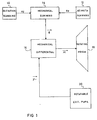
- Fig. 1 is a block diagram- illustration of the peritelescope constructed and operative in accordance with a preferred embodiment of the present invention.
- the peritelescope comprises elevation scanning apparatus 10 which is operative to orient an elevation beam reflecting surface, such as a mirror or prism, at a predetermined angle ⁇ about the y axis.
- the peritelescope also comprises azimuth scanning apparatus 12 which is operative to orient an azimuth beam reflecting surface, such as a mirror or prism, at a predetermined angle ⁇ about the z axis.
- Apparatus 10 and apparatus 12 are mechanically coupled by a mechanical summing device 14, preferably a differential which provides a rotational mechanical output about the z axis which may be expressed as:
- the mechanical output from summing device 14 is supplied to a second mechanical differential 16, which is operative to provide a rotational mechanical output ⁇ to a rotatable image orientation compensation prism 18 and is also mechanically coupled to a rotatable exit pupil 20, whose orientation about the z axis is indicated as ⁇ .
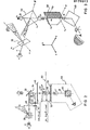
- FIG. 2 is a schematic illustration of a preferred embodiment of the peritelescope of the present invention indicating the mechanical linkages between the various elements.
- FIGs. 4 and 5 are pictorial illustrations of portions of the apparatus of Fig. 2.
- An elevation mirror 30 is seen to be mounted for selectable rotation about the Y-axis.
- the Y-axis is defined to lie in a plane perpendicular to the Z-axis, which extends vertically.
- the orientation of elevation mirror 30 with respect to the Y-axis is defined by an angle ⁇ .
- An azimuth mirror 32 is arranged to receive radiation reflected from elevation mirror 30 and is mounted for rotation about the Z-axis.
- the orientation of azimuth mirror 32 about the Z-axis with respect to a predetermined reference is indicated by ⁇ .
- Fixedly mounted onto aximuth mirror 32 for rotation together therewith about the Z-axis is a right angled rotational mounting element 34, including a first portion 36 extending parallel to the Z-axis and a second portion 38 extending in a plane parallel to the Y-axis.
- a gear or gear equivalent 40 Coupled to elevation mirror 30 for rotation together therewith about the Y-axis is a gear or gear equivalent 40.
- Element 40 engages an intermediate gear element 42 which is rotatably mounted with respect to portion 38.
- Fixedly mounted with respect to intermediate gear element 42 and rotatably mounted with respect to portion 39 is a bevel wheel type gear 44, which in turn engages a summing bevel wheel type gear or equivalent 46, which is arranged for rotation about the Z-axis.
- the effective gear ratio between element 40 and summing gear 46 is +1 : +1.
- elements 34, 40, 42, 44 and 46 perform a summing function in accordance with the following equation: where i is the angular orientation of element 46 about the Z-axis with respect to a predetermined reference.
- Element 46 is fixedly coupled to a parallel bevel gear type or equivalent element 48 which also rotates about the Z-axis,together with element 46.
- Element 48 defines one gear of a differential 50, which also comprises an intermediate gear 52 and a terminal gear 54, which is also arranged for rotation about the Z-axis.
- Rotatably mounted with respect to intermediate gear 52 is a rotation prism 56 which is operative to correct the received image for distortions produced by image rotation.
- the mounting of prism 56 is such that it is rotatable about the Z-axis, its orientation about the Z-axis being given by ⁇ .
- a movable exit pupil assembly 58 comprising a viewing mirror 60, or its equivalent.
- the orientation of the viewing mirror 60 about the Z-axis is indicated by ⁇ .
- the differential 50 is arranged to define the following relationship between the elements and orientations defined hereinabove:
- the movable exit pupil assembly 58 may be moved to any desired position about the Z-axis and the viewer will see the same scene, since the appropriate corrections to the image are being made automatically by suitable rotation of the rotating prism 56, through operation of the differential 50.
- Fig. 3 is an optical diagrammatical illustration of the peritelescope illustrated in Fig. 2.
- Fig. 3 is an optical diagrammatical illustration of the peritelescope illustrated in Fig. 2.
- the same reference numbers are used in Fig. 3 as in Fig. 2 to indicate corresponding elements.
- an important feature of the present invention lies in the fact that the reflected beams lie parallel to the rotation axes of the rotating elements.
- the elevation mirror 30 is oriented such as to provide a reflected beam along the Y axis to the azimuth mirror 32, which, in turn, provides a reflected beam along the Z-axis to the viewing mirror 60 or its equivalent.
- the feature that the reflected beams lie parallel to the rotation axes of the rotating mirror elements is important since it enables 360 degree scanning by each of the elements.
- a dove prism 56 or its equivalent, which is rotatably mounted about the Z-axis in a manner described hereinabove.
Landscapes
- Physics & Mathematics (AREA)
- General Physics & Mathematics (AREA)
- Optics & Photonics (AREA)
- Astronomy & Astrophysics (AREA)
- Compounds Of Alkaline-Earth Elements, Aluminum Or Rare-Earth Metals (AREA)
- Prostheses (AREA)
- Endoscopes (AREA)
- Mechanical Optical Scanning Systems (AREA)
- Lenses (AREA)
- Telescopes (AREA)
Abstract
Description
- The present invention relates to optical apparatus providing selectably directional viewing along an azimuth generally and more particularly to peritelescopes.
- Various types of peritelescopes are known in the art and are available on the market. Most of the peritelescopes presently on the market have limitations in their range both in azimuth and in elevation. In order to overcome the limitations in elevation range, most of the devices employ a pivotable elevation scan mirror or prism which pivots about an axis extending through the mirror and extending perpendicularly to the beam of light reflected or refracted thereby.
- This prior art structure imposes a limitation at high elevation angles, approaching 90 degrees to the horizontal, wherein the dimensions of the mirror or prism limit the extreme elevation angles which can be realized.
- There is also known peritelescope apparatus wherein azimuth scanning is provided by rotation of the elevation mirror assembly about a rotation axis which is parallel to the beam reflected by the elevation mirror assembly..The image distortion produced thereby is corrected by means of a rotating prism which rotates in the azimuth by an angle equal to one-half of the rotation of the elevation mirror assembly from a predetermined reference.
- "The present invention seeks to provide an improved peritelescope having significantly enhanced performance as compared with the prior art.
- There is thus provided in accordance with a preferred embodiment of the present invention a peritelescope comprising elevation scanning apparatus and azimuth scanning apparatus, the elevation scanning apparatus and azimuth scanning apparatus being operative and cooperative to provide a 360 degree field of view in elevation and a 360 degree field of view in azimuth.
- Further in accordance with a preferred embodiment of the present invention there is provided a peritelescope comprising elevation scanning apparatus and azimuth scanning apparatus, the elevation scanning apparatus comprising pivotable beam reflecting means which are pivotable about an axis parallel to the beam reflected thereby.
- Additionally in accordance with a preferred embodiment of the present invention there is provided a peritelescope comprising elevation scanning apparatus and azimuth scanning apparatus, the elevation scanning apparatus comprising pivotable beam reflecting means which are pivotable about an axis parallel to the beam reflected thereby.
- Additionally in accordance with a preferred embodiment of the present invention, there is provided a peritelescope comprising elevation scanning apparatus and azimuth scanning apparatus, the azimuth scanning apparatus comprising pivotable azimuth beam reflecting means arranged for pivotal motion about an elevation scanning axis and the azimuth scanning apparatus comprising pivotable azimuth beam reflecting means arranged for pivotal motion about an azimuth scanning axis and wherein the elevation beam reflecting means is spaced from the azimuth scanning axis.
- Further in accordance with an embodiment of the present invention, there is provided a peritelescope comprising elevation scanning apparatus, azimuth scanning apparatus, and image orientation correction apparatus, the elevation scanning apparatus comprising pivotable elevation beam reflecting apparatus arranged for pivotal motion about an elevation scanning axis and the azimuth scanning apparatus comprising pivotable azimuth beam reflecting means arranged for pivotal motion about an azimuth scanning axis and wherein the image orientation correction apparatus comprises a rotating optical element, and apparatus for causing rotation of the rotating optical element as a function of the rotation of the elevation beam reflecting apparatus about the elevation scanning axis and of the rotation of the azimuth beam reflecting apparatus about the azimuth scanning axis.
- Further in accordance with an embodiment of the present invention, the apparatus for causing rotation comprises a differential.
- Still further in accordance with an embodiment of the invention there is provided a peritelescope comprising elevation ! scanning apparatus, azimuth scanning apparatus, image orientation correction apparatus, and a movable exit pupil, the elevation scanning apparatus comprising pivotable elevation beam reflecting apparatus arranged for pivotal motion about an elevation scanning axis and the azimuth scanning apparatus comprising pivotable azimuth beam reflecting means arranged for pivotal motion about an azimuth scanning axis and wherein the movable exit pupil is pivotable about the azimuth scanning axis.
- Additionally in accordance with a preferred embodiment of the present invention, there is provided exit pupil differential coupling apparatus for coupling the movable exit pupil to the image orientation correction apparatus, whereby rotation of the exit pupil about the azimuth scanning axis does not affect the image seen therethrough.
- The present invention will be understood and appreciated more fully from the following detailed description taken in conjunction with the drawings in which:
- Fig. 1 is a block diagram mechanical illustration of a peritelescope constructed and operative in accordance with a preferred embodiment of the invention;
- Fig. 2 is a schematic illustration of the peritelescope of the present invention indicating the mechanical linkages between the various elements;
- Fig. 3 is an optical diagrammatical illustration of the peritelescope illustrated in Fig. 2;
- Fig. 4 is a pictorial illustration of a portion of the peritelescope illustrated in Fig. 2; and
- Fig. 5 is a pictorial illustration of another portion of the peritelescope illustrated in Fig. 2.
- Reference is now made to Fig. 1, which is a block diagram- illustration of the peritelescope constructed and operative in accordance with a preferred embodiment of the present invention. The peritelescope comprises
elevation scanning apparatus 10 which is operative to orient an elevation beam reflecting surface, such as a mirror or prism, at a predetermined angle α about the y axis. The peritelescope also comprisesazimuth scanning apparatus 12 which is operative to orient an azimuth beam reflecting surface, such as a mirror or prism, at a predetermined angle β about the z axis. -
Apparatus 10 andapparatus 12 are mechanically coupled by amechanical summing device 14, preferably a differential which provides a rotational mechanical output about the z axis which may be expressed as:
- The mechanical output from
summing device 14 is supplied to a secondmechanical differential 16, which is operative to provide a rotational mechanical output µ to a rotatable imageorientation compensation prism 18 and is also mechanically coupled to arotatable exit pupil 20, whose orientation about the z axis is indicated as γ. - The angular relationship between µ, ℓ and ℓγ is given as follows:
- Reference is now made to Fig. 2 which is a schematic illustration of a preferred embodiment of the peritelescope of the present invention indicating the mechanical linkages between the various elements. Reference is also made to Figs. 4 and 5 which are pictorial illustrations of portions of the apparatus of Fig. 2. An
elevation mirror 30 is seen to be mounted for selectable rotation about the Y-axis. The Y-axis is defined to lie in a plane perpendicular to the Z-axis, which extends vertically. The orientation ofelevation mirror 30 with respect to the Y-axis is defined by an angle α. - An
azimuth mirror 32 is arranged to receive radiation reflected fromelevation mirror 30 and is mounted for rotation about the Z-axis. The orientation ofazimuth mirror 32 about the Z-axis with respect to a predetermined reference is indicated by β. Fixedly mounted ontoaximuth mirror 32 for rotation together therewith about the Z-axis is a right angledrotational mounting element 34, including afirst portion 36 extending parallel to the Z-axis and asecond portion 38 extending in a plane parallel to the Y-axis. - Coupled to
elevation mirror 30 for rotation together therewith about the Y-axis is a gear or gear equivalent 40.Element 40 engages anintermediate gear element 42 which is rotatably mounted with respect toportion 38. Fixedly mounted with respect tointermediate gear element 42 and rotatably mounted with respect to portion 39 is a bevelwheel type gear 44, which in turn engages a summing bevel wheel type gear or equivalent 46, which is arranged for rotation about the Z-axis. The effective gear ratio betweenelement 40 and summinggear 46 is +1 : +1. - It may be appreciated that
elements 
where i is the angular orientation ofelement 46 about the Z-axis with respect to a predetermined reference. -
Element 46 is fixedly coupled to a parallel bevel gear type orequivalent element 48 which also rotates about the Z-axis,together withelement 46.Element 48 defines one gear of adifferential 50, which also comprises anintermediate gear 52 and aterminal gear 54, which is also arranged for rotation about the Z-axis. - Rotatably mounted with respect to
intermediate gear 52 is arotation prism 56 which is operative to correct the received image for distortions produced by image rotation. The mounting ofprism 56 is such that it is rotatable about the Z-axis, its orientation about the Z-axis being given by µ. - Fixedly mounted onto
element 54 for rotation about the Z-axis is a movableexit pupil assembly 58 comprising aviewing mirror 60, or its equivalent. The orientation of theviewing mirror 60 about the Z-axis is indicated by γ. - The
differential 50 is arranged to define the following relationship between the elements and orientations defined hereinabove:
- It may be appreciated that the movable
exit pupil assembly 58 may be moved to any desired position about the Z-axis and the viewer will see the same scene, since the appropriate corrections to the image are being made automatically by suitable rotation of therotating prism 56, through operation of thedifferential 50. - Reference is now made to Fig. 3 which is an optical diagrammatical illustration of the peritelescope illustrated in Fig. 2. For simplicity, the same reference numbers are used in Fig. 3 as in Fig. 2 to indicate corresponding elements.
- It is seen that an important feature of the present invention lies in the fact that the reflected beams lie parallel to the rotation axes of the rotating elements. Particularly it is seen that the
elevation mirror 30 is oriented such as to provide a reflected beam along the Y axis to theazimuth mirror 32, which, in turn, provides a reflected beam along the Z-axis to theviewing mirror 60 or its equivalent. - The feature that the reflected beams lie parallel to the rotation axes of the rotating mirror elements is important since it enables 360 degree scanning by each of the elements.
- Correction of image distortions produced by rotation is provided by a
dove prism 56, or its equivalent, which is rotatably mounted about the Z-axis in a manner described hereinabove. - It will be appreciated by persons skilled in the art that the present invention is not limited to what has been particularly shown and described hereinabove. Rather the scope of the present invention is defined only by the claims which follow:
Claims (7)
Priority Applications (1)
| Application Number | Priority Date | Filing Date | Title |
|---|---|---|---|
| AT85201087T ATE52142T1 (en) | 1984-07-13 | 1985-07-05 | PANORAMIC TELESCOPE. |
Applications Claiming Priority (2)
| Application Number | Priority Date | Filing Date | Title |
|---|---|---|---|
| IL72406 | 1984-07-13 | ||
| IL72406A IL72406A (en) | 1984-07-13 | 1984-07-13 | Peritelescope |
Publications (2)
| Publication Number | Publication Date |
|---|---|
| EP0170317A1 true EP0170317A1 (en) | 1986-02-05 |
| EP0170317B1 EP0170317B1 (en) | 1990-04-18 |
Family
ID=11055198
Family Applications (1)
| Application Number | Title | Priority Date | Filing Date |
|---|---|---|---|
| EP85201087A Expired - Lifetime EP0170317B1 (en) | 1984-07-13 | 1985-07-05 | Peritelescope |
Country Status (4)
| Country | Link |
|---|---|
| EP (1) | EP0170317B1 (en) |
| AT (1) | ATE52142T1 (en) |
| DE (1) | DE3577235D1 (en) |
| IL (1) | IL72406A (en) |
Cited By (4)
| Publication number | Priority date | Publication date | Assignee | Title |
|---|---|---|---|---|
| FR2592962A1 (en) * | 1986-01-14 | 1987-07-17 | Theodor Preussner | PANORAMIC PERISCOPE. |
| EP0518733A1 (en) * | 1991-06-14 | 1992-12-16 | AEROSPATIALE Société Nationale Industrielle | Method and scanning device for an optoelectronic wide angle imaging apparatus with high resolution |
| EP2884327A1 (en) * | 2013-12-13 | 2015-06-17 | Airbus Defence and Space SAS | Scanning optical system for space observation |
| EP3757651B1 (en) * | 2019-06-05 | 2023-09-20 | Schott Ag | Optical apparatus and method for high resolution image transmission |
Citations (4)
| Publication number | Priority date | Publication date | Assignee | Title |
|---|---|---|---|---|
| US2488239A (en) * | 1946-05-17 | 1949-11-15 | Mergenthaler Linotype Gmbh | Panoramic telescope |
| FR1341222A (en) * | 1962-12-13 | 1963-10-25 | Hensoldt Und Sohne M | Panoramic telescope |
| FR1514377A (en) * | 1967-01-13 | 1968-02-23 | Thomson Houston Comp Francaise | Unlimited Exploration Periscopic Riflescopes Improvements |
| DE2833944A1 (en) * | 1978-08-03 | 1980-02-21 | Ludwig Dipl Ing Dr In Pietzsch | Optical sighting appts. mounted on vehicle - has drive stabilising objective on target in observed area |
-
1984
- 1984-07-13 IL IL72406A patent/IL72406A/en unknown
-
1985
- 1985-07-05 AT AT85201087T patent/ATE52142T1/en not_active IP Right Cessation
- 1985-07-05 EP EP85201087A patent/EP0170317B1/en not_active Expired - Lifetime
- 1985-07-05 DE DE8585201087T patent/DE3577235D1/en not_active Expired - Lifetime
Patent Citations (4)
| Publication number | Priority date | Publication date | Assignee | Title |
|---|---|---|---|---|
| US2488239A (en) * | 1946-05-17 | 1949-11-15 | Mergenthaler Linotype Gmbh | Panoramic telescope |
| FR1341222A (en) * | 1962-12-13 | 1963-10-25 | Hensoldt Und Sohne M | Panoramic telescope |
| FR1514377A (en) * | 1967-01-13 | 1968-02-23 | Thomson Houston Comp Francaise | Unlimited Exploration Periscopic Riflescopes Improvements |
| DE2833944A1 (en) * | 1978-08-03 | 1980-02-21 | Ludwig Dipl Ing Dr In Pietzsch | Optical sighting appts. mounted on vehicle - has drive stabilising objective on target in observed area |
Cited By (10)
| Publication number | Priority date | Publication date | Assignee | Title |
|---|---|---|---|---|
| FR2592962A1 (en) * | 1986-01-14 | 1987-07-17 | Theodor Preussner | PANORAMIC PERISCOPE. |
| GB2187303A (en) * | 1986-01-14 | 1987-09-03 | Theodor Preussner | Panoramic periscope |
| GB2187303B (en) * | 1986-01-14 | 1989-12-06 | Theodor Preussner | Panoramic periscope |
| EP0518733A1 (en) * | 1991-06-14 | 1992-12-16 | AEROSPATIALE Société Nationale Industrielle | Method and scanning device for an optoelectronic wide angle imaging apparatus with high resolution |
| FR2677775A1 (en) * | 1991-06-14 | 1992-12-18 | Aerospatiale | METHOD AND SCANNING DEVICE FOR A HIGH-FIELD, HIGH-RESOLUTION OPTOELECTRONIC VIEWING DEVICE |
| US5223969A (en) * | 1991-06-14 | 1993-06-29 | Societe Anonyme Dite: Aerospatiale Societe Nationale Industrielle | Scanning method and apparatus for an opto-electronic camera having high resolution and a large field of view |
| EP2884327A1 (en) * | 2013-12-13 | 2015-06-17 | Airbus Defence and Space SAS | Scanning optical system for space observation |
| FR3015056A1 (en) * | 2013-12-13 | 2015-06-19 | Astrium Sas | SPACE SPATIAL OBSERVATION OPTICAL SYSTEM |
| US9207446B2 (en) | 2013-12-13 | 2015-12-08 | Airbus Defence And Space Sas | Scanning space observation optical system |
| EP3757651B1 (en) * | 2019-06-05 | 2023-09-20 | Schott Ag | Optical apparatus and method for high resolution image transmission |
Also Published As
| Publication number | Publication date |
|---|---|
| IL72406A (en) | 1990-03-19 |
| EP0170317B1 (en) | 1990-04-18 |
| IL72406A0 (en) | 1984-11-30 |
| DE3577235D1 (en) | 1990-05-23 |
| ATE52142T1 (en) | 1990-05-15 |
Similar Documents
| Publication | Publication Date | Title |
|---|---|---|
| US5168386A (en) | Flat field telecentric scanner | |
| US4576432A (en) | Aiming or sighting apparatus with synchronously rotating thermal imager and aiming head | |
| US8169708B2 (en) | Projecting optical unit and projecting type image display apparatus therewith | |
| EP0538671B1 (en) | Seeker, mainly for missile guidance | |
| EP1307776B1 (en) | An image altering device for an image producing apparatus | |
| JPH0587805B2 (en) | ||
| EP0170317A1 (en) | Peritelescope | |
| US4155620A (en) | Rotating mirror optical scanner with flat scan and linear scan rate | |
| US4202597A (en) | Optical scanning system with compensation for unwanted image rotation during scanning | |
| JP2567877B2 (en) | Distortion correction device | |
| EP0071531A1 (en) | Scanning mechanism for flir systems | |
| JPS617818A (en) | Optical scanner | |
| US4912321A (en) | Radiation scanning system with pupil control | |
| DE3434841A1 (en) | OPTICAL LASER BEAM DEFLECTION SYSTEM | |
| Verboven | Distortion correction formulas for pre-objective dual galvanometer laser scanning | |
| US4504110A (en) | Converging beam linear optical scanner | |
| GB1377426A (en) | Method of and apparatus for photographint a subject by line scanning | |
| JPH0723313U (en) | Optically flat bed scanner | |
| US5223969A (en) | Scanning method and apparatus for an opto-electronic camera having high resolution and a large field of view | |
| US4788423A (en) | Two-mirror scanning system | |
| GB1516432A (en) | Revolutionary scheimpflug visual probe | |
| EP0270338A3 (en) | Improved viewfinder | |
| EP0309205B1 (en) | Postobjective optical deflector | |
| US5204783A (en) | Focusing apparatus for a folded collimating lens in an x-ray imaging system | |
| US3143732A (en) | Image rotation system |
Legal Events
| Date | Code | Title | Description |
|---|---|---|---|
| PUAI | Public reference made under article 153(3) epc to a published international application that has entered the european phase |
Free format text: ORIGINAL CODE: 0009012 |
|
| AK | Designated contracting states |
Designated state(s): AT BE CH DE FR GB IT LI LU NL SE |
|
| 17P | Request for examination filed |
Effective date: 19860725 |
|
| 17Q | First examination report despatched |
Effective date: 19870615 |
|
| GRAA | (expected) grant |
Free format text: ORIGINAL CODE: 0009210 |
|
| AK | Designated contracting states |
Kind code of ref document: B1 Designated state(s): AT BE CH DE FR GB IT LI LU NL SE |
|
| PG25 | Lapsed in a contracting state [announced via postgrant information from national office to epo] |
Ref country code: SE Effective date: 19900418 Ref country code: NL Effective date: 19900418 Ref country code: IT Free format text: LAPSE BECAUSE OF FAILURE TO SUBMIT A TRANSLATION OF THE DESCRIPTION OR TO PAY THE FEE WITHIN THE PRESCRIBED TIME-LIMIT;WARNING: LAPSES OF ITALIAN PATENTS WITH EFFECTIVE DATE BEFORE 2007 MAY HAVE OCCURRED AT ANY TIME BEFORE 2007. THE CORRECT EFFECTIVE DATE MAY BE DIFFERENT FROM THE ONE RECORDED. Effective date: 19900418 Ref country code: BE Effective date: 19900418 Ref country code: AT Effective date: 19900418 |
|
| REF | Corresponds to: |
Ref document number: 52142 Country of ref document: AT Date of ref document: 19900515 Kind code of ref document: T |
|
| ET | Fr: translation filed | ||
| REF | Corresponds to: |
Ref document number: 3577235 Country of ref document: DE Date of ref document: 19900523 |
|
| PG25 | Lapsed in a contracting state [announced via postgrant information from national office to epo] |
Ref country code: LU Free format text: LAPSE BECAUSE OF NON-PAYMENT OF DUE FEES Effective date: 19900731 |
|
| NLV1 | Nl: lapsed or annulled due to failure to fulfill the requirements of art. 29p and 29m of the patents act | ||
| PLBE | No opposition filed within time limit |
Free format text: ORIGINAL CODE: 0009261 |
|
| STAA | Information on the status of an ep patent application or granted ep patent |
Free format text: STATUS: NO OPPOSITION FILED WITHIN TIME LIMIT |
|
| 26N | No opposition filed | ||
| PGFP | Annual fee paid to national office [announced via postgrant information from national office to epo] |
Ref country code: GB Payment date: 19920623 Year of fee payment: 8 |
|
| PGFP | Annual fee paid to national office [announced via postgrant information from national office to epo] |
Ref country code: CH Payment date: 19920721 Year of fee payment: 8 |
|
| PGFP | Annual fee paid to national office [announced via postgrant information from national office to epo] |
Ref country code: DE Payment date: 19920725 Year of fee payment: 8 |
|
| PGFP | Annual fee paid to national office [announced via postgrant information from national office to epo] |
Ref country code: FR Payment date: 19920729 Year of fee payment: 8 |
|
| PG25 | Lapsed in a contracting state [announced via postgrant information from national office to epo] |
Ref country code: GB Effective date: 19930705 |
|
| PG25 | Lapsed in a contracting state [announced via postgrant information from national office to epo] |
Ref country code: LI Effective date: 19930731 Ref country code: CH Effective date: 19930731 |
|
| GBPC | Gb: european patent ceased through non-payment of renewal fee |
Effective date: 19930705 |
|
| PG25 | Lapsed in a contracting state [announced via postgrant information from national office to epo] |
Ref country code: FR Effective date: 19940331 |
|
| REG | Reference to a national code |
Ref country code: CH Ref legal event code: PL |
|
| PG25 | Lapsed in a contracting state [announced via postgrant information from national office to epo] |
Ref country code: DE Effective date: 19940401 |
|
| REG | Reference to a national code |
Ref country code: FR Ref legal event code: ST |