EP0168941A1 - Portable unit, e.g. for the recovery of divers - Google Patents
Portable unit, e.g. for the recovery of divers Download PDFInfo
- Publication number
- EP0168941A1 EP0168941A1 EP85304017A EP85304017A EP0168941A1 EP 0168941 A1 EP0168941 A1 EP 0168941A1 EP 85304017 A EP85304017 A EP 85304017A EP 85304017 A EP85304017 A EP 85304017A EP 0168941 A1 EP0168941 A1 EP 0168941A1
- Authority
- EP
- European Patent Office
- Prior art keywords
- unit
- hatchway
- unit according
- hatch cover
- annular member
- Prior art date
- Legal status (The legal status is an assumption and is not a legal conclusion. Google has not performed a legal analysis and makes no representation as to the accuracy of the status listed.)
- Withdrawn
Links
Images


Classifications
-
- B—PERFORMING OPERATIONS; TRANSPORTING
- B63—SHIPS OR OTHER WATERBORNE VESSELS; RELATED EQUIPMENT
- B63C—LAUNCHING, HAULING-OUT, OR DRY-DOCKING OF VESSELS; LIFE-SAVING IN WATER; EQUIPMENT FOR DWELLING OR WORKING UNDER WATER; MEANS FOR SALVAGING OR SEARCHING FOR UNDERWATER OBJECTS
- B63C11/00—Equipment for dwelling or working underwater; Means for searching for underwater objects
- B63C11/02—Divers' equipment
- B63C11/32—Decompression arrangements; Exercise equipment
- B63C11/325—Decompression arrangements; Exercise equipment chambers used for it
Definitions
- This invention relates to a portable unit in which a desired pressure may be maintained, for example for the recovery of divers suffering from the bends.
- a portable unit in which a desired pressure may be maintained and which is capable of transporting therein a person, the unit comprising a flexible body for housing the person, the body having an entrance forming a hatchway, and a rigid hatch cover for sealing the hatchway, the unit being provided with an inlet for compressed gas and a valve whereby the pressure in the unit may be regulated.
- the unit of the invention may be submerged to the depth of the diver, who is placed inside the unit.
- the unit is then sealed and air is drawn from a demand valve to be discharged into the unit.
- the required pressure may then be set in the unit by means of an adjustable release valve.
- the air discharged from the demand valve into the unit then causes water in the unit to leave via the release valve.
- the unit ascends to the surface of the water maintaining the preset pressure.
- air may be discharged from the demand valve to expel any water from within the unit so that the unit may be transferred with the diver inside.
- the unit may also be used to transfer a suffering diver for treatment on land.
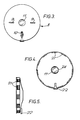
- the hatch cover 8 is provided with two handles 9, an adjustable release valve 10 and a 4 inch laminated glass port hole 11.
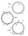
- FIG. 6 shows the hatchway 20(which may be aluminium cast and machined for a good fit)fitted into the entrance of the unit.
- the outer rubber flange 3 fits over the hatchway 20, exposing an interrupted thread 13 for attachment purposes.
- the body 1 has a steel ring 12 laminated to a flange la of the entrance of the body 1.
- the hatchway 20 consists of an annular member 14, shown in Figure 7, and, in cross-section, at the lower part of Figure 11.
- This annular member 14 is provided in a front face 14a thereof with an annular recess 15 for locating the steel ring 12 in a manner to be described hereinafter.
- the annular member 14 is further provided with a plurality of screw holes 16 around the circumference of the front face 14a, and carries the interrupted thread 13.
- the annular member 14 of the hatchway 20 is inserted into the entrance of the body 1 so that the steel ring 12 is located in the annular recess 15. This is shown in Figure 10, and, in more detail, in the cross-section of Figure 12.
- An inner rubber flange 17 locates the annular member 14 with respect to the steel ring 12, the annular member being secured in place by way of an annular plate 18 (also shown in Figure 8) which is screwed onto the annular member 14 using screws 19 in corresponding holes 16.
- the unit is shown from the front, with the hatchway 20 thus constructed. As shown in Figure 6, it is protected from the outside by the outer rubber flange 3.
- the hatchway 20 is now ready to receive the hatch cover 8, shown from the front in Figure 3, from the rear in Figure 4 and from the side in Figure 5.
- Figure 11 shows a partial cross-section through the hatch cover 8 before it is positioned in the hatchway 20 and
- Figure 13 shows a cross-section through the hatch cover 8 and hatchway 20, with the hatch cover 8 in position.
- the hatch cover 8 has two handles 9 and a laminated glass port hole 11 and is provided with an adjustable release valve 10.
- the circumference of the hatch cover 8 has an interrupted thread 21 to cooperate with the interrupted thread 13 on the hatchway 20.
- the adjustable release valve has an outlet 22 provided with a filter 23 ( Figure 13).
- a rubber seal 24 is provided between the port hole 11 and main body of the hatch cover 8 .
- the length of the unit is 7' ( ⁇ 2 m)
- the body 1 and hatchway 8 once constructed, may be stored in a conveniently sized container (for the embodiment illustrated above having the dimensions 26" (66cm) x 26" (66cm) x 18" (45.7cm), and weighing only 65lbs (29.5kg)).
- the hatch cover 20 may be attached to the hatchway 8 by arranging for one part of the interrupted screw thread 21 on the hatch cover 20 to face a space between the parts of the interrupted screw thread 13 of the hatchway 8, inserting the hatch cover 20 into the hatchway 8 and twisting it so that the screw threads engage. To remove the cover 20 the reverse procedure is carried out.
- a diver may draw air from the demand air valve (not shown), exhaling the air into the unit to inflate it to the required pressure.
- the adjustable release valve 10 is set, from outside the unit using a gauge 10a, at the required pressure so that excess air or water, as the case may be, is discharged via the valve 10.
- the bottles 6 may be easily replaced if necessary.
- the two air bottles 6 are removed and the body 1 is rolled up to be placed in a storage container with the air bottles 6.
- the described embodiment can operate at pressures between 14.7 lbs psi Hl bar) and 30 lbs psi ( ⁇ 2 bar), and may be quickly assembled ( in about 3 minutes) for use.
- divers need no longer be submerged unconscious, to a required depth of water but may be placed in the unit and moved for treatment without further risk.
- the diver's equipment may be removed when the diver is in the unit.
- the unit described above may be carried by hand without difficulty and assembled quickly for a recovery operation.
Abstract
There ist described a portable unit in which a desired pressure may be maintained and which is capable of transporting therein a person, the unit comprising a flexible body for housing the person, the body having an entrance forming a hatchway, and a rigid hatchway cover for sealing the hatchway, the unit being provided with an inlet for compressed gas and a valve whereby the pressure in the unit may be regulated. The unit may be used in the rescue of a diver.
Description
- This invention relates to a portable unit in which a desired pressure may be maintained, for example for the recovery of divers suffering from the bends.
- When resurfacing rapidly, a diver is at risk of suffering from the bends, caused by the rapid decrease in pressure to which his body is subjected as he rises to the surface of the water. The diver who suffers from the bends under water is at a great risk of his condition deteriorating as he continues to rise to the surface of the water to be transferred for treatment.
- Presently, many underwater operations are conducted using rigid diving bells which must be lifted up from, or lowered to, the sea bed with a crane or similar lifting device. Such bells are heavy and inflexiblewhich makes them difficult to manoeuvre and awkward to handle both on land and underwater.
- According to the present invention there is provided a portable unit in which a desired pressure may be maintained and which is capable of transporting therein a person, the unit comprising a flexible body for housing the person, the body having an entrance forming a hatchway, and a rigid hatch cover for sealing the hatchway, the unit being provided with an inlet for compressed gas and a valve whereby the pressure in the unit may be regulated.
- The unit of the invention may be submerged to the depth of the diver, who is placed inside the unit. The unit is then sealed and air is drawn from a demand valve to be discharged into the unit. The required pressure, according to the depth at which the unit is submerged ,may then be set in the unit by means of an adjustable release valve. The air discharged from the demand valve into the unit then causes water in the unit to leave via the release valve. As a result of the buoyancy of the air, the unit ascends to the surface of the water maintaining the preset pressure. When the unit has surfaced, air may be discharged from the demand valve to expel any water from within the unit so that the unit may be transferred with the diver inside.
- The unit may also be used to transfer a suffering diver for treatment on land.
- For a better understanding of the present invention, and to show how the same may be carried into effect, reference will now be made, by way of example, to the accompanying drawings, in which:-
- Figuresl and 2 are an end view and side view of the assembled unit, respectively;
- Figures 3, 4 and 5 are a front, reverse and side view respectively of a hatch cover used to seal the entrance of the diving unit;
- Figures 6 to 10 illustrate the entrance of the diving unit at various stages during its construction;
- Figure 11 is a cross-section of the hatch cover of Figures 3 to 5, also showing, in cross-section, part of the entrance of the unit;
- Figure 12 is a partial cross-section of the entrance of the diving unit; and
- Figure 13 is a cross-section of the hatch cover in place in the entrance.
- Figures 1 and 2 show an assembled unit in accordance with one embodiment of the present invention. The unit comprises a flexible body 1, for example formed of canvas, having two
canvas side pockets 2 and anouter rubber flange 3 at the entrance to the unit. The body 1 is further provided with fourhandles 4, two along each side of the body 1, and two lifting eyes 5. Thepockets 2 each carry a gas cylinder, preferably containing air at 3000 lb psi (207 bar). Thegas cylinders 6 each have a content gauge and a demand valve, which are not shown in detail in the drawings as these items are standard equipment on air cylinders used for diving purposes. Air may be supplied to the unit by way of an air supply point 7, which is connected to the demand valve of the cylinders6. - The entrance of the body 1 is closed by a
hatch cover 8 to be described in more detail hereinafter. Briefly, thehatch cover 8 is provided with two handles 9, anadjustable release valve 10 and a 4 inch laminatedglass port hole 11. - The body 1 of the unit is provided with a
hatchway 20 for receiving thehatch cover 8. The construction of the hatchway will now be described in detail with reference to Figures 6 to 10. Figure 6 shows the hatchway 20(which may be aluminium cast and machined for a good fit)fitted into the entrance of the unit. Theouter rubber flange 3 fits over thehatchway 20, exposing aninterrupted thread 13 for attachment purposes. - As shown in Figure 9, the body 1 has a
steel ring 12 laminated to a flange la of the entrance of the body 1. Thehatchway 20 consists of anannular member 14, shown in Figure 7, and, in cross-section, at the lower part of Figure 11. Thisannular member 14 is provided in afront face 14a thereof with anannular recess 15 for locating thesteel ring 12 in a manner to be described hereinafter. Theannular member 14 is further provided with a plurality ofscrew holes 16 around the circumference of thefront face 14a, and carries theinterrupted thread 13. - To construct the hatchway for use of the unit, the
annular member 14 of thehatchway 20 is inserted into the entrance of the body 1 so that thesteel ring 12 is located in theannular recess 15. This is shown in Figure 10, and, in more detail, in the cross-section of Figure 12. Aninner rubber flange 17 locates theannular member 14 with respect to thesteel ring 12, the annular member being secured in place by way of an annular plate 18 (also shown in Figure 8) which is screwed onto theannular member 14 usingscrews 19 incorresponding holes 16. In Figure 8, the unit is shown from the front, with thehatchway 20 thus constructed. As shown in Figure 6, it is protected from the outside by theouter rubber flange 3. - The
hatchway 20 is now ready to receive thehatch cover 8, shown from the front in Figure 3, from the rear in Figure 4 and from the side in Figure 5. Figure 11 shows a partial cross-section through thehatch cover 8 before it is positioned in thehatchway 20 and Figure 13 shows a cross-section through thehatch cover 8 andhatchway 20, with thehatch cover 8 in position. - As has been described with reference to Figure 1, and as shown more clearly in Figures 3 and 4, the
hatch cover 8 has two handles 9 and a laminatedglass port hole 11 and is provided with anadjustable release valve 10. The circumference of thehatch cover 8 has aninterrupted thread 21 to cooperate with theinterrupted thread 13 on thehatchway 20. The adjustable release valve has anoutlet 22 provided with a filter 23 (Figure 13). Arubber seal 24 is provided between theport hole 11 and main body of thehatch cover 8 . - The illustrated embodiment has the following dimensions:
- Internal diameter of
plate 18, a = 221" (56.5cm) Maximum and minimum internal diameters of theannular member 14, b = 21 1 2n (54.6cm) c = 21" (53.3cm) - Diameter of
port hole 11, d = 5" (12.7cm) Diameter ofport hole 11 including therubber seal 24, e = 41" (13.3cm) - Diameter of a centre portion of the
hatch cover 20, f, = 4" (10.2cm) - Diameter of the
hatch cover 20, g = 21" (53.3cm) h = 212" (54.6cm) i = 22" (55.9cm) - Width of the
annular member 14 of thehatchway 8, j = 2 3/8" (6cm) - External width of the
annular member 14 of thehatchway 8, k = 2 1/8" (5.4cm) - Length of the
annular member 14, q, = 2 3/4" (7cm) Length of thescrew 19 ,ℓ = 1 1/8" (2.9cm) and for theplate 18, m = 1 2" (1.27cm), n = 1 2" (1.27cm), o = 1 3/16" (3cm) and p = 1 3/4" (4.4cm) - In use, the length of the unit is 7' (~ 2 m)
- The body 1 and
hatchway 8, once constructed, may be stored in a conveniently sized container (for the embodiment illustrated above having the dimensions 26" (66cm) x 26" (66cm) x 18" (45.7cm), and weighing only 65lbs (29.5kg)). Thehatch cover 20 may be attached to thehatchway 8 by arranging for one part of the interruptedscrew thread 21 on thehatch cover 20 to face a space between the parts of the interruptedscrew thread 13 of thehatchway 8, inserting thehatch cover 20 into thehatchway 8 and twisting it so that the screw threads engage. To remove thecover 20 the reverse procedure is carried out. With twoair bottles 6 in position in thecanvas pockets 2 of the body 1, a diver may draw air from the demand air valve (not shown), exhaling the air into the unit to inflate it to the required pressure. Theadjustable release valve 10 is set, from outside the unit using a gauge 10a, at the required pressure so that excess air or water, as the case may be, is discharged via thevalve 10. Thebottles 6 may be easily replaced if necessary. Theair bottles 6, in addition to providing air via the demand valve, act as a ballast to ensure that the unit is held the correct way up in the water when a diver is being carried by the unit, thus ensuring removal of all the water from the unit. They also stabilise the unit in transit. - To store the unit, the two
air bottles 6 are removed and the body 1 is rolled up to be placed in a storage container with theair bottles 6. - The described embodiment can operate at pressures between 14.7 lbs psi Hl bar) and 30 lbs psi (~2 bar), and may be quickly assembled ( in about 3 minutes) for use.
- Accordingly, divers need no longer be submerged unconscious, to a required depth of water but may be placed in the unit and moved for treatment without further risk. The diver's equipment may be removed when the diver is in the unit.
- The unit described above may be carried by hand without difficulty and assembled quickly for a recovery operation.
Claims (10)
1. A portable unit in which a desired pressure may be maintained and which is capable of transporting therein a person, the unit comprising a flexible body for housing the person, the body having an entrance forming a hatchway, and a rigid hatch cover for sealing the hatchway, the unit being provided with an inlet for compressed gas and a valve whereby the pressure in the unit may be regulated.
2. A unit according to Claim 1, wherein the hatchway comprises an annular member adapted to be located at the entrance of the flexible body by an inwardly directed flange of the flexible body.
3. A unit according to Claim 2, wherein a rigid ring is provided on the inner surface of the flange extending around the flange, the ring being disposed to cooperate, in use of the device, with a corresponding groove in the annular member.
4. A unit according to Claim 2 or 3, wherein the annular member is secured at the entrance of the flexible body by an annular plate by which the annular member is clamped to the flange.
5. A unit according to any preceding claim, wherein the circumference of the hatchway has an interrupted thread to cooperate, in use of the device, with an interrupted thread on the hatchway.
6. A unit according to any preceding claim wherein the pressure in the unit is regulated by an adjustable release valve provided in the hatch cover.
7. A unit according to any preceding claim, wherein the hatch cover is provided with a glass port hole.
8. A unit according to any preceding claim, wherein the hatch cover has at least one handle.
9. A unit according to any preceding claim, wherein the flexible body is formed of canvas.
10. A unit according to any preceding claim, wherein the hatch cover is formed of aluminium.
Applications Claiming Priority (2)
| Application Number | Priority Date | Filing Date | Title |
|---|---|---|---|
| GB8414476 | 1984-06-06 | ||
| GB08414476A GB2159862A (en) | 1984-06-06 | 1984-06-06 | A portable unit in which a desired pressure may be maintained and which is capable of transporting therein a person |
Publications (1)
| Publication Number | Publication Date |
|---|---|
| EP0168941A1 true EP0168941A1 (en) | 1986-01-22 |
Family
ID=10562038
Family Applications (1)
| Application Number | Title | Priority Date | Filing Date |
|---|---|---|---|
| EP85304017A Withdrawn EP0168941A1 (en) | 1984-06-06 | 1985-06-06 | Portable unit, e.g. for the recovery of divers |
Country Status (2)
| Country | Link |
|---|---|
| EP (1) | EP0168941A1 (en) |
| GB (1) | GB2159862A (en) |
Cited By (5)
| Publication number | Priority date | Publication date | Assignee | Title |
|---|---|---|---|---|
| WO1990008692A2 (en) * | 1989-01-27 | 1990-08-09 | Courtaulds Plc | Pressure vessels |
| WO1996028341A1 (en) * | 1995-03-16 | 1996-09-19 | Gse Giunio Santi Engineering S.R.L. | Flexible hyperbaric chamber |
| US6062215A (en) * | 1997-07-22 | 2000-05-16 | Kinetic Concepts, Inc. | Hyperbaric oxygen patient treatment system |
| DE10235842A1 (en) * | 2002-05-17 | 2003-11-27 | Peter Leitholf | Transport system for divers comprises a transport vessel and a diving capsule in the form of a closable floating body which incorporates a chamber for a diver, and is fillable with water while in operation |
| WO2008104159A2 (en) * | 2007-02-27 | 2008-09-04 | Peter Leitholf | Leitholf-type diving capsule |
Families Citing this family (2)
| Publication number | Priority date | Publication date | Assignee | Title |
|---|---|---|---|---|
| GB9926514D0 (en) * | 1999-11-10 | 2000-01-12 | Burnup Alex | Pressure vessel |
| GB2457737A (en) * | 2008-02-25 | 2009-08-26 | Survitec Group Ltd | Portable flexible compression chamber |
Citations (4)
| Publication number | Priority date | Publication date | Assignee | Title |
|---|---|---|---|---|
| GB191507228A (en) * | 1914-08-03 | 1915-12-30 | Draegerwerk Ag | Improvements in or relating to Recompression Chambers for Divers. |
| FR1406060A (en) * | 1964-06-03 | 1965-07-16 | Portable pressure relief box of flexible construction | |
| FR1460707A (en) * | 1965-09-28 | 1966-03-04 | Flexible portable recompression chamber | |
| US3729002A (en) * | 1971-04-01 | 1973-04-24 | D Miller | Emergency inflatable recompression unit |
Family Cites Families (2)
| Publication number | Priority date | Publication date | Assignee | Title |
|---|---|---|---|---|
| US3299645A (en) * | 1964-01-02 | 1967-01-24 | Ocean Systems | Underwater capsule |
| US3387580A (en) * | 1965-10-22 | 1968-06-11 | Harold H. Walker | Submersible water craft |
-
1984
- 1984-06-06 GB GB08414476A patent/GB2159862A/en not_active Withdrawn
-
1985
- 1985-06-06 EP EP85304017A patent/EP0168941A1/en not_active Withdrawn
Patent Citations (4)
| Publication number | Priority date | Publication date | Assignee | Title |
|---|---|---|---|---|
| GB191507228A (en) * | 1914-08-03 | 1915-12-30 | Draegerwerk Ag | Improvements in or relating to Recompression Chambers for Divers. |
| FR1406060A (en) * | 1964-06-03 | 1965-07-16 | Portable pressure relief box of flexible construction | |
| FR1460707A (en) * | 1965-09-28 | 1966-03-04 | Flexible portable recompression chamber | |
| US3729002A (en) * | 1971-04-01 | 1973-04-24 | D Miller | Emergency inflatable recompression unit |
Non-Patent Citations (1)
| Title |
|---|
| MECHANICAL ENGINEERING, vol. 102, no. 3, March 1980, page 56, Published by the American Society of Mechanical Engineers, New York, US; "Underwater parachute for scuba divers" * |
Cited By (11)
| Publication number | Priority date | Publication date | Assignee | Title |
|---|---|---|---|---|
| WO1990008692A2 (en) * | 1989-01-27 | 1990-08-09 | Courtaulds Plc | Pressure vessels |
| WO1990008692A3 (en) * | 1989-01-27 | 1990-10-18 | Courtaulds Plc | Pressure vessels |
| GB2245630A (en) * | 1989-01-27 | 1992-01-08 | Courtaulds Plc | Pressure vessels |
| GB2245630B (en) * | 1989-01-27 | 1992-09-16 | Courtaulds Plc | Pressure vessels |
| US5255673A (en) * | 1989-01-27 | 1993-10-26 | Courtaulds Plc & Sos Limited | Pressure vessels |
| WO1996028341A1 (en) * | 1995-03-16 | 1996-09-19 | Gse Giunio Santi Engineering S.R.L. | Flexible hyperbaric chamber |
| US6062215A (en) * | 1997-07-22 | 2000-05-16 | Kinetic Concepts, Inc. | Hyperbaric oxygen patient treatment system |
| DE10235842A1 (en) * | 2002-05-17 | 2003-11-27 | Peter Leitholf | Transport system for divers comprises a transport vessel and a diving capsule in the form of a closable floating body which incorporates a chamber for a diver, and is fillable with water while in operation |
| DE10235842B4 (en) * | 2002-05-17 | 2008-01-31 | Leitholf, Peter, Dipl.-Ing. | Transport system for divers and diving capsule |
| WO2008104159A2 (en) * | 2007-02-27 | 2008-09-04 | Peter Leitholf | Leitholf-type diving capsule |
| WO2008104159A3 (en) * | 2007-02-27 | 2008-12-04 | Peter Leitholf | Leitholf-type diving capsule |
Also Published As
| Publication number | Publication date |
|---|---|
| GB2159862A (en) | 1985-12-11 |
| GB8414476D0 (en) | 1984-07-11 |
Similar Documents
| Publication | Publication Date | Title |
|---|---|---|
| US4771299A (en) | Method and apparatus for underwater operation of non-waterproof equipment | |
| US3602221A (en) | Portable recompression chamber | |
| US4227524A (en) | Hyperbaric transfer system | |
| US4674493A (en) | Underwater breathing apparatus | |
| US3729002A (en) | Emergency inflatable recompression unit | |
| US8020722B2 (en) | Seamless multi-section pressure vessel | |
| US7174844B2 (en) | Simulator and method for performing underwater submarine escape training | |
| EP0168941A1 (en) | Portable unit, e.g. for the recovery of divers | |
| CN1136521A (en) | Simple diving respirator | |
| US4771320A (en) | Method and apparatus for extending the depth range of underwater equipment | |
| EP0245343A1 (en) | Diving apparatus and methods of operating same | |
| US5887585A (en) | Air supply life vest | |
| EP0437948A1 (en) | Underwater breathing apparatus | |
| US1294188A (en) | Pressure-chamber for removing divers' diseases. | |
| US4753474A (en) | Apparatus and system for carrying, storing and connecting scuba tanks together | |
| DE10235842B4 (en) | Transport system for divers and diving capsule | |
| US3631551A (en) | Prepackaged monopropellant gas generator buoyancy system | |
| US4274405A (en) | Method for varying the ambient pressure in a vessel | |
| WO2022208349A1 (en) | A hyperbaric chamber | |
| US3464217A (en) | Portable diving appliance | |
| RU2037735C1 (en) | High-pressure cylinder | |
| GB2164259A (en) | Shallow water breathing apparatus | |
| WO2003097445A1 (en) | Diving capsule and transport system for divers | |
| US3473337A (en) | Mobile underwater power plant | |
| US2936755A (en) | Safety device for skin divers |
Legal Events
| Date | Code | Title | Description |
|---|---|---|---|
| PUAI | Public reference made under article 153(3) epc to a published international application that has entered the european phase |
Free format text: ORIGINAL CODE: 0009012 |
|
| AK | Designated contracting states |
Designated state(s): AT BE CH DE FR GB IT LI LU NL SE |
|
| STAA | Information on the status of an ep patent application or granted ep patent |
Free format text: STATUS: THE APPLICATION IS DEEMED TO BE WITHDRAWN |
|
| 18D | Application deemed to be withdrawn |
Effective date: 19860923 |