EP0168124B1 - Limiteur de couple - Google Patents
Limiteur de couple Download PDFInfo
- Publication number
- EP0168124B1 EP0168124B1 EP85301510A EP85301510A EP0168124B1 EP 0168124 B1 EP0168124 B1 EP 0168124B1 EP 85301510 A EP85301510 A EP 85301510A EP 85301510 A EP85301510 A EP 85301510A EP 0168124 B1 EP0168124 B1 EP 0168124B1
- Authority
- EP
- European Patent Office
- Prior art keywords
- discs
- spring
- clutch
- axial movement
- shaft
- Prior art date
- Legal status (The legal status is an assumption and is not a legal conclusion. Google has not performed a legal analysis and makes no representation as to the accuracy of the status listed.)
- Expired
Links
Images

Classifications
-
- F—MECHANICAL ENGINEERING; LIGHTING; HEATING; WEAPONS; BLASTING
- F16—ENGINEERING ELEMENTS AND UNITS; GENERAL MEASURES FOR PRODUCING AND MAINTAINING EFFECTIVE FUNCTIONING OF MACHINES OR INSTALLATIONS; THERMAL INSULATION IN GENERAL
- F16D—COUPLINGS FOR TRANSMITTING ROTATION; CLUTCHES; BRAKES
- F16D43/00—Automatic clutches
- F16D43/02—Automatic clutches actuated entirely mechanically
- F16D43/20—Automatic clutches actuated entirely mechanically controlled by torque, e.g. overload-release clutches, slip-clutches with means by which torque varies the clutching pressure
- F16D43/21—Automatic clutches actuated entirely mechanically controlled by torque, e.g. overload-release clutches, slip-clutches with means by which torque varies the clutching pressure with friction members
- F16D43/213—Automatic clutches actuated entirely mechanically controlled by torque, e.g. overload-release clutches, slip-clutches with means by which torque varies the clutching pressure with friction members with axially applied torque-limiting friction surfaces
- F16D43/215—Automatic clutches actuated entirely mechanically controlled by torque, e.g. overload-release clutches, slip-clutches with means by which torque varies the clutching pressure with friction members with axially applied torque-limiting friction surfaces with flat friction surfaces, e.g. discs
- F16D43/216—Automatic clutches actuated entirely mechanically controlled by torque, e.g. overload-release clutches, slip-clutches with means by which torque varies the clutching pressure with friction members with axially applied torque-limiting friction surfaces with flat friction surfaces, e.g. discs with multiple lamellae
-
- F—MECHANICAL ENGINEERING; LIGHTING; HEATING; WEAPONS; BLASTING
- F16—ENGINEERING ELEMENTS AND UNITS; GENERAL MEASURES FOR PRODUCING AND MAINTAINING EFFECTIVE FUNCTIONING OF MACHINES OR INSTALLATIONS; THERMAL INSULATION IN GENERAL
- F16D—COUPLINGS FOR TRANSMITTING ROTATION; CLUTCHES; BRAKES
- F16D59/00—Self-acting brakes, e.g. coming into operation at a predetermined speed
-
- F—MECHANICAL ENGINEERING; LIGHTING; HEATING; WEAPONS; BLASTING
- F16—ENGINEERING ELEMENTS AND UNITS; GENERAL MEASURES FOR PRODUCING AND MAINTAINING EFFECTIVE FUNCTIONING OF MACHINES OR INSTALLATIONS; THERMAL INSULATION IN GENERAL
- F16H—GEARING
- F16H35/00—Gearings or mechanisms with other special functional features
- F16H35/10—Arrangements or devices for absorbing overload or preventing damage by overload
-
- G—PHYSICS
- G05—CONTROLLING; REGULATING
- G05G—CONTROL DEVICES OR SYSTEMS INSOFAR AS CHARACTERISED BY MECHANICAL FEATURES ONLY
- G05G15/00—Mechanical devices for initiating a movement automatically due to a specific cause
- G05G15/08—Mechanical devices for initiating a movement automatically due to a specific cause due to the load or torque on a member, e.g. if exceeding a predetermined value thereof
Definitions
- This invention relates to devices for limiting torque applied to a shaft, and in particular to torque limiters including an indicator for showing that torque limitation has occurred. It is known from US-A-3596740 to provide a device for limiting the torque applied by a shaft.
- a torque limiting device may incorporate a ball or roller clutch in which relative movement against a spring between input and output members of the clutch occurs only when a predetermined level of torque is exceeded, this relative movement resulting in application of a brake.
- a further spring may provide a reaction device for the brake. If the torque subsequently falls below the aforesaid predetermined value the brake is released and the transmission continues to operate normally. However, since application of the brake may indicate a malfunction of the actuator system driven thereby, it is desirable that an indicator device shall be provided which shows that braking has occurred.
- US-A-3701401 reflects the preamble of claim 1 and discloses a torque limiter having an indicator which operates in response to relative rotation between parts of the torque limiter mechanism.
- this prior art torque limiter however, such relative movement may occur transiently and without being of sufficient magnitude to operate the brake. If an indication is provided in response to such transient phenomena, the transmission and actuator system will subsequently be dismantled in an attempt to locate a non-existent fault.
- an input shaft 10 has keyed thereto an annular clutch input element 11. .
- a face of the element 11 is directed towards an opposed face of an annular clutch output element 12.
- the opposed faces of the elements 11, 12 are provided with a plurality of aligned and circumferentially spaced recesses 13, 14 in which balls 15 are located.
- the element 12 is biassed towads the element 11 by means of a plurality of spring washers 16 which surround the shaft 10.
- a hollow output shaft 17 is in splined engagement with the output element 12.
- a plurality of annular brake discs 18 is slidably and non-rotatably mounted on an axially-extending part of the output element 12.
- a plurality of brake discs 19 is intercalated with the discs 18 and slidably and non-rotatably engage a plurality of pins 20 mounted in a fixed housing 21.
- a sleeve 22 is mounted on the shaft 10 and has an abutment face which engages one end of the stack of discs 18, 19, the other end of this stack being engaged by a spacer ring 23 which also engages the element 12.
- the shaft 10 is restrained by means (not shown) against axial movement relative to the housing 21 and the sleeve 22 is biassed against a flange 28 on the shaft 10 by spring washers 24 located between the sleeve 22 and a collar 25 which is located by means of a further sleeve 26 surrounding the sleeve 22.
- a small axial clearance 27 exists between the sleeve 26 and the sleeve 22 when the latter abuts the flange 28.
- a ball 30 is located in a through hole in the sleeve 26 and engages a recess in a plunger 31 to restrain the latter against axial movement under the influence of a spring 32.
- a corresponding recess 33 is located on the sleeve 22 so as to be displaced axially from the ball 30 by an amount equal to the clearance 27 when the sleeve 22 abuts the flange 28.
- Figures 2 and 3 show part sections of an alternative embodiment and represent part-sections at the same axial location, but in different transverse planes.
- An input shaft 40 is journalled in a housing 41 by a bearing 42.
- An annular clutch input element 43 is keyed to the shaft 40 and an.
- annular clutch output element 44 is in splined engagement with a hollow output shaft 45.
- a plurality of balls 46 are engaged between pairs of opposed recesses in the elements 43, 44 in a like manner to that described with reference to Figure 1.
- a stack of intercalated annular brake discs 47, 48 are non-rotatably supported on the element 44 and a pin 49 and are axially located between an annular spacer 50 and an annular abutment 51.
- the abutment 51 runs on a thrust bearing 52 which is supported by a collar 53 carried by the shaft 40.
- the clutch element 44 is biased towards the element 43 by a spring 54 engaged between the abutment 51 and the element 44.
- Spring washers 55 are engaged between the spacer 50 and the clutch element 44.
- the periphery of the clutch element 44 has a ramped portion 56 which can engage a stem 57.
- the stem 57 is slidablefin a bore which forms part of the housing 41.
- the spring washers 55 between the clutch element 44 and the spacer 50 do not, in normal use, apply an axial force to the discs 47, 48.
- Displacement of the circlip 58 and consequent movement of the plunger 57 to a radially outward position under the influence of a spring 59 provides an indication that full braking has occurred.
- subsequent removal of the torque overload on the shaft45 allowsthe balls 46 to be reseated in the aligned recesses and drive to the output shaft 45 to be resumed.
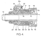
- an input shaft 70 is in splined engagement with an annular clutch input element 71.
- a face of the input element 71 is directed towards an opposed face of an annular clutch output element 72.
- the opposed faces of the elements 71, 72 are provided with a plurality of aligned and circumferentially spaced recesses 73, 74 in which balls 75 are located.
- the element 72 is biassed towards the element 71 by a stack of spring washers which surround the element 71 and abut a sleeve 77 which is axially slidable on the element 71.
- a hollow output shaft 78 is in driving engagement with the element72 by means of dogs 79.
- a relatively fixed housing 80 surrounds the parts described above and the sleeve 77 is prevented from rotating relative to the housing 80 by suitable means, as for example by splined engagement therewith.
- a plurality of brake discs 81 is slidably and non-rotatably mounted on an axially-extending part of the output element 72.
- a plurality of brake discs 82 intercalated with the discs 81.
- the discs 82 are axially movable with respect to the housing 80 but are prevented from rotating. Conveniently the discs 82 engage axially-extending projections on the sleeve 77.
- the sleeve 77 is maintained in a rightward position, as viewed in the drawing, so as to maintain a slight pre-loading of the spring washer stack 76, by a double spring washer arrangement 83.
- the arrangement 83 acts between a fixed abutment 84 on the element 71 and a collar 85 which has limited sliding movement.
- a plunger 90 is frictionally engaged in the housing 80 and engages a face on the sleeve 77 so as to be urged outwardly by leftward movement of the sleeve 77.
- An outer end of the plunger 90 engages an indicator arm 91 to urge the latter radially outwardly in response to leftward movement of the sleeve 77.
- the arrangement 83 has greater stiffness than that of the stack 76 which ensures thatthe aforesaid movement of the sleeve 77 occurs only after braking of the output shaft 78 has been fully effected.
- Leftward movement of the sleeve 77 causes the indicator arm 91 to be lifted to the position shown at 91a, in which position it is maintained by a spring latch 92 in the housing 80.
- the arm 91 Since movement of the arm 91 occurs only in response to movement of the sleeve 77 after braking has occurred, the arm 91 does not provide an indication in response to transient relative movements between the elements 71, 72 of the clutch.
Claims (3)
Applications Claiming Priority (2)
| Application Number | Priority Date | Filing Date | Title |
|---|---|---|---|
| GB8407029 | 1984-03-17 | ||
| GB8407029 | 1984-03-17 |
Publications (2)
| Publication Number | Publication Date |
|---|---|
| EP0168124A1 EP0168124A1 (fr) | 1986-01-15 |
| EP0168124B1 true EP0168124B1 (fr) | 1988-12-28 |
Family
ID=10558281
Family Applications (1)
| Application Number | Title | Priority Date | Filing Date |
|---|---|---|---|
| EP85301510A Expired EP0168124B1 (fr) | 1984-03-17 | 1985-03-05 | Limiteur de couple |
Country Status (4)
| Country | Link |
|---|---|
| US (1) | US4625843A (fr) |
| EP (1) | EP0168124B1 (fr) |
| JP (1) | JPS60211136A (fr) |
| DE (1) | DE3567084D1 (fr) |
Cited By (3)
| Publication number | Priority date | Publication date | Assignee | Title |
|---|---|---|---|---|
| EP0296713A1 (fr) * | 1987-06-20 | 1988-12-28 | LUCAS INDUSTRIES public limited company | Arrangement à limitation de couple |
| EP0550261A2 (fr) * | 1991-12-28 | 1993-07-07 | Itoh Electric Co. Ltd. | Dispositif de transmission pour force motrice |
| EP0727594A2 (fr) * | 1995-02-18 | 1996-08-21 | Lucas Industries Public Limited Company | Limitateur de couple |
Families Citing this family (29)
| Publication number | Priority date | Publication date | Assignee | Title |
|---|---|---|---|---|
| US4990122A (en) * | 1987-12-21 | 1991-02-05 | Sundstrand Corporation | Shaft failure indicator |
| US4793120A (en) * | 1987-12-24 | 1988-12-27 | Herzog Kenneth J | Clutch and cap disc assembly |
| US4898265A (en) * | 1988-01-27 | 1990-02-06 | Sundstrand Corporation | Torque limiter |
| US4850458A (en) * | 1988-11-16 | 1989-07-25 | Boeing Company | Bidirectional rotary brake |
| DE4100829C1 (fr) * | 1991-01-14 | 1992-07-23 | Gkn Cardantec International Gesellschaft Fuer Antriebstechnik Mbh, 4300 Essen, De | |
| US5238093A (en) * | 1992-08-28 | 1993-08-24 | Dana Corporation | Wear indicator for adjustable clutch |
| DE19503051A1 (de) * | 1995-02-01 | 1996-08-08 | Zahnradfabrik Friedrichshafen | Linearantrieb für die Verstellung eines Elementes, insbesondere eines Flügelelementes an einem Flugzeug |
| US5785158A (en) * | 1996-02-01 | 1998-07-28 | Sundstrand Corporation | Brake apparatus with functional integrity monitor |
| US5901817A (en) * | 1997-04-18 | 1999-05-11 | The Boeing Company | Torque limiter with trip indicator |
| US6109415A (en) * | 1998-05-29 | 2000-08-29 | The Boeing Company | Bi-directional ballscrew no-back device |
| US5944148A (en) * | 1998-08-31 | 1999-08-31 | The Boeing Company | No-back brake |
| GB9823599D0 (en) | 1998-10-28 | 1998-12-23 | Lucas Ind Plc | Brake assembly |
| US6810656B2 (en) | 2002-12-12 | 2004-11-02 | Honeywell International, Inc. | Thrust reverser system power drive unit with dual sequential torque decoupler and method |
| US6786315B1 (en) | 2003-03-28 | 2004-09-07 | Honeywell International, Inc. | Thrust reverser system with sequential torque decoupler |
| US6974107B2 (en) | 2003-06-18 | 2005-12-13 | Honeywell International, Inc. | Thrust reverser system actuator having an integral torque limiter |
| WO2008095163A1 (fr) * | 2007-02-01 | 2008-08-07 | Curtiss Wright Controls Inc. | Frein dynamométrique |
| GB0806104D0 (en) * | 2008-04-04 | 2008-05-14 | Goodrich Actuation Systems Ltd | Torque limiter with brake |
| US8281678B2 (en) * | 2008-12-30 | 2012-10-09 | Eaton Corporation | Ballscrew assembly with detection feature |
| US20110132369A1 (en) * | 2009-12-04 | 2011-06-09 | Nellcor Puritan Bennett Llc | Ventilation System With System Status Display |
| CN101837938B (zh) * | 2009-12-30 | 2012-09-26 | 浙江诺和机电有限公司 | 一种单向载荷自制螺旋式制动器 |
| US8539949B2 (en) | 2010-04-27 | 2013-09-24 | Covidien Lp | Ventilation system with a two-point perspective view |
| US8453643B2 (en) | 2010-04-27 | 2013-06-04 | Covidien Lp | Ventilation system with system status display for configuration and program information |
| US8511306B2 (en) | 2010-04-27 | 2013-08-20 | Covidien Lp | Ventilation system with system status display for maintenance and service information |
| USD645158S1 (en) | 2010-04-27 | 2011-09-13 | Nellcor Purtian Bennett LLC | System status display |
| TW201348012A (zh) * | 2012-05-25 | 2013-12-01 | Hon Hai Prec Ind Co Ltd | 傳動軸制動裝置及傳動裝置 |
| USD775345S1 (en) | 2015-04-10 | 2016-12-27 | Covidien Lp | Ventilator console |
| US10066683B2 (en) * | 2015-04-10 | 2018-09-04 | Goodrich Corporation | Clutch for a winch |
| FR3065043B1 (fr) * | 2017-04-06 | 2019-05-10 | Safran Electronics & Defense | Dispositif limiteur de couple, notamment pour la commande d'une gouverne de vol |
| EP3421831B1 (fr) | 2017-06-29 | 2020-07-15 | Hamilton Sundstrand Corporation | Indicateur pour limiteur de couple |
Citations (2)
| Publication number | Priority date | Publication date | Assignee | Title |
|---|---|---|---|---|
| US3596740A (en) * | 1970-01-27 | 1971-08-03 | Trw Inc | Torque limiter |
| US3701401A (en) * | 1971-05-12 | 1972-10-31 | Curtiss Wright Corp | Torque overload sensing and indicating device for torque limiting brake mechanism |
Family Cites Families (11)
| Publication number | Priority date | Publication date | Assignee | Title |
|---|---|---|---|---|
| US1883164A (en) * | 1931-02-24 | 1932-10-18 | Leonidas A Vassakos | Coupling |
| FR1012377A (fr) * | 1949-07-28 | 1952-07-09 | Renault | Dispositif limiteur de force |
| DE1046421B (de) * | 1952-11-21 | 1958-12-11 | Johann Vollenbroich | Elektromagnetisch betaetigte Scheibenreibungskupplung oder -bremse |
| US2859846A (en) * | 1955-09-02 | 1958-11-11 | Sylvania Electric Prod | Overload relief mechanism |
| FR1196018A (fr) * | 1957-11-18 | 1959-11-20 | Latimier Soc | Accouplement ou dispositif transmetteur de couple à limiteur de couple |
| GB979487A (en) * | 1960-04-14 | 1965-01-06 | Fisher & Ludlow Ltd | A new or improved overload clutch or torque limiting device |
| US3329243A (en) * | 1965-12-29 | 1967-07-04 | Gen Electric | Torque brake |
| US3675745A (en) * | 1971-03-09 | 1972-07-11 | Marcel Pierre Alexis Bouhot | Double acting free wheel |
| GB1370011A (en) * | 1972-04-07 | 1974-10-09 | Gib Precision Ltd | Torque limitting devices |
| US3802281A (en) * | 1972-10-26 | 1974-04-09 | Lucas Aerospace Ltd | Driving arrangements for leadscrews |
| SU434205A1 (ru) * | 1973-03-13 | 1974-06-30 | Предохранительная муфта |
-
1985
- 1985-03-05 DE DE8585301510T patent/DE3567084D1/de not_active Expired
- 1985-03-05 EP EP85301510A patent/EP0168124B1/fr not_active Expired
- 1985-03-11 US US06/710,067 patent/US4625843A/en not_active Expired - Lifetime
- 1985-03-18 JP JP60052565A patent/JPS60211136A/ja active Pending
Patent Citations (2)
| Publication number | Priority date | Publication date | Assignee | Title |
|---|---|---|---|---|
| US3596740A (en) * | 1970-01-27 | 1971-08-03 | Trw Inc | Torque limiter |
| US3701401A (en) * | 1971-05-12 | 1972-10-31 | Curtiss Wright Corp | Torque overload sensing and indicating device for torque limiting brake mechanism |
Cited By (5)
| Publication number | Priority date | Publication date | Assignee | Title |
|---|---|---|---|---|
| EP0296713A1 (fr) * | 1987-06-20 | 1988-12-28 | LUCAS INDUSTRIES public limited company | Arrangement à limitation de couple |
| EP0550261A2 (fr) * | 1991-12-28 | 1993-07-07 | Itoh Electric Co. Ltd. | Dispositif de transmission pour force motrice |
| EP0550261A3 (en) * | 1991-12-28 | 1993-12-08 | Itoh Electric Co Ltd | Device for driving power transmission |
| EP0727594A2 (fr) * | 1995-02-18 | 1996-08-21 | Lucas Industries Public Limited Company | Limitateur de couple |
| US5630490A (en) * | 1995-02-18 | 1997-05-20 | Lucas Industries Public Limited Company | Torque limiter |
Also Published As
| Publication number | Publication date |
|---|---|
| JPS60211136A (ja) | 1985-10-23 |
| EP0168124A1 (fr) | 1986-01-15 |
| DE3567084D1 (de) | 1989-02-02 |
| US4625843A (en) | 1986-12-02 |
Similar Documents
| Publication | Publication Date | Title |
|---|---|---|
| EP0168124B1 (fr) | Limiteur de couple | |
| US4898265A (en) | Torque limiter | |
| CN1818409B (zh) | 无反力及转矩限制器的联合装置 | |
| US5655636A (en) | Compact actuator including resettable force limiting and anti-backdrive devices | |
| US3367456A (en) | Torque sensitive brake | |
| US4095681A (en) | Safety braking device for a unit moving along a surface, in particular for a lift car | |
| US4834225A (en) | No-back mechanism | |
| US4094387A (en) | Inertia dependent device for preventing and permitting relative rotation between two members | |
| CN109790908B (zh) | 过载保护装置 | |
| US2432591A (en) | Clutch | |
| JPH073253B2 (ja) | 手動復帰式オーバーロードクラッチ | |
| US4597477A (en) | Bidirectional brake | |
| GB2231112A (en) | Safety winding apparatus | |
| US6419606B1 (en) | Aircraft control surface drive apparatus | |
| US4890711A (en) | Clutch control system for an automobile vehicle, and a clutch release bearing therefor | |
| US3835973A (en) | Torque limiting device | |
| US3038576A (en) | Torque limiting and overload sensing device | |
| EP2830986B1 (fr) | Ensemble comprenant un appareil de sécurité pour équiper un dispositif de levage, en particulier un treuil, et système permettant d'actionner ledit appareil | |
| US4293060A (en) | Electromagnetic friction clutch with overload release | |
| US4864882A (en) | Torque limiting arrangement | |
| US20020144876A1 (en) | Torque limiter | |
| US2859846A (en) | Overload relief mechanism | |
| EP3447325B1 (fr) | Système indicateur pour limiteur de couple | |
| US4199964A (en) | Thrust transmission or thrust producing device | |
| US4809834A (en) | Multiple plate clutch release proportioning device |
Legal Events
| Date | Code | Title | Description |
|---|---|---|---|
| PUAI | Public reference made under article 153(3) epc to a published international application that has entered the european phase |
Free format text: ORIGINAL CODE: 0009012 |
|
| AK | Designated contracting states |
Designated state(s): DE FR GB IT |
|
| RIN1 | Information on inventor provided before grant (corrected) |
Inventor name: PARKER, RAY Inventor name: MALTBY, PETER JOHN |
|
| 17P | Request for examination filed |
Effective date: 19860627 |
|
| 17Q | First examination report despatched |
Effective date: 19870824 |
|
| GRAA | (expected) grant |
Free format text: ORIGINAL CODE: 0009210 |
|
| AK | Designated contracting states |
Kind code of ref document: B1 Designated state(s): DE FR GB IT |
|
| REF | Corresponds to: |
Ref document number: 3567084 Country of ref document: DE Date of ref document: 19890202 |
|
| ET | Fr: translation filed | ||
| ITF | It: translation for a ep patent filed |
Owner name: SOCIETA' ITALIANA BREVETTI S.P.A. |
|
| PLBE | No opposition filed within time limit |
Free format text: ORIGINAL CODE: 0009261 |
|
| STAA | Information on the status of an ep patent application or granted ep patent |
Free format text: STATUS: NO OPPOSITION FILED WITHIN TIME LIMIT |
|
| 26N | No opposition filed | ||
| ITTA | It: last paid annual fee | ||
| REG | Reference to a national code |
Ref country code: GB Ref legal event code: IF02 |
|
| PGFP | Annual fee paid to national office [announced via postgrant information from national office to epo] |
Ref country code: GB Payment date: 20030305 Year of fee payment: 19 |
|
| PGFP | Annual fee paid to national office [announced via postgrant information from national office to epo] |
Ref country code: FR Payment date: 20030310 Year of fee payment: 19 |
|
| PGFP | Annual fee paid to national office [announced via postgrant information from national office to epo] |
Ref country code: DE Payment date: 20030313 Year of fee payment: 19 |
|
| REG | Reference to a national code |
Ref country code: GB Ref legal event code: 732E |
|
| PG25 | Lapsed in a contracting state [announced via postgrant information from national office to epo] |
Ref country code: GB Free format text: LAPSE BECAUSE OF NON-PAYMENT OF DUE FEES Effective date: 20040305 |
|
| PG25 | Lapsed in a contracting state [announced via postgrant information from national office to epo] |
Ref country code: DE Free format text: LAPSE BECAUSE OF NON-PAYMENT OF DUE FEES Effective date: 20041001 |
|
| GBPC | Gb: european patent ceased through non-payment of renewal fee | ||
| PG25 | Lapsed in a contracting state [announced via postgrant information from national office to epo] |
Ref country code: FR Free format text: LAPSE BECAUSE OF NON-PAYMENT OF DUE FEES Effective date: 20041130 |
|
| REG | Reference to a national code |
Ref country code: FR Ref legal event code: ST |