EP0168055A2 - Armature for direct current motor - Google Patents
Armature for direct current motor Download PDFInfo
- Publication number
- EP0168055A2 EP0168055A2 EP85108707A EP85108707A EP0168055A2 EP 0168055 A2 EP0168055 A2 EP 0168055A2 EP 85108707 A EP85108707 A EP 85108707A EP 85108707 A EP85108707 A EP 85108707A EP 0168055 A2 EP0168055 A2 EP 0168055A2
- Authority
- EP
- European Patent Office
- Prior art keywords
- openings
- imbalance
- armature
- motor
- shaft
- Prior art date
- Legal status (The legal status is an assumption and is not a legal conclusion. Google has not performed a legal analysis and makes no representation as to the accuracy of the status listed.)
- Granted
Links
- 239000007769 metal material Substances 0.000 description 23
- 238000000034 method Methods 0.000 description 15
- 239000011347 resin Substances 0.000 description 9
- 229920005989 resin Polymers 0.000 description 9
- 230000000694 effects Effects 0.000 description 5
- 239000000463 material Substances 0.000 description 5
- 239000013598 vector Substances 0.000 description 5
- 238000007796 conventional method Methods 0.000 description 3
- XEEYBQQBJWHFJM-UHFFFAOYSA-N Iron Chemical compound [Fe] XEEYBQQBJWHFJM-UHFFFAOYSA-N 0.000 description 2
- 239000000945 filler Substances 0.000 description 2
- 230000002093 peripheral effect Effects 0.000 description 2
- RYGMFSIKBFXOCR-UHFFFAOYSA-N Copper Chemical compound [Cu] RYGMFSIKBFXOCR-UHFFFAOYSA-N 0.000 description 1
- 229910052782 aluminium Inorganic materials 0.000 description 1
- XAGFODPZIPBFFR-UHFFFAOYSA-N aluminium Chemical compound [Al] XAGFODPZIPBFFR-UHFFFAOYSA-N 0.000 description 1
- 229910052802 copper Inorganic materials 0.000 description 1
- 239000010949 copper Substances 0.000 description 1
- 230000008030 elimination Effects 0.000 description 1
- 238000003379 elimination reaction Methods 0.000 description 1
- 238000003780 insertion Methods 0.000 description 1
- 230000037431 insertion Effects 0.000 description 1
- 229910052742 iron Inorganic materials 0.000 description 1
- 239000011133 lead Substances 0.000 description 1
- 238000004904 shortening Methods 0.000 description 1
Images

Classifications
-
- F—MECHANICAL ENGINEERING; LIGHTING; HEATING; WEAPONS; BLASTING
- F16—ENGINEERING ELEMENTS AND UNITS; GENERAL MEASURES FOR PRODUCING AND MAINTAINING EFFECTIVE FUNCTIONING OF MACHINES OR INSTALLATIONS; THERMAL INSULATION IN GENERAL
- F16F—SPRINGS; SHOCK-ABSORBERS; MEANS FOR DAMPING VIBRATION
- F16F15/00—Suppression of vibrations in systems; Means or arrangements for avoiding or reducing out-of-balance forces, e.g. due to motion
- F16F15/32—Correcting- or balancing-weights or equivalent means for balancing rotating bodies, e.g. vehicle wheels
-
- H—ELECTRICITY
- H02—GENERATION; CONVERSION OR DISTRIBUTION OF ELECTRIC POWER
- H02K—DYNAMO-ELECTRIC MACHINES
- H02K7/00—Arrangements for handling mechanical energy structurally associated with dynamo-electric machines, e.g. structural association with mechanical driving motors or auxiliary dynamo-electric machines
- H02K7/04—Balancing means
-
- Y—GENERAL TAGGING OF NEW TECHNOLOGICAL DEVELOPMENTS; GENERAL TAGGING OF CROSS-SECTIONAL TECHNOLOGIES SPANNING OVER SEVERAL SECTIONS OF THE IPC; TECHNICAL SUBJECTS COVERED BY FORMER USPC CROSS-REFERENCE ART COLLECTIONS [XRACs] AND DIGESTS
- Y10—TECHNICAL SUBJECTS COVERED BY FORMER USPC
- Y10T—TECHNICAL SUBJECTS COVERED BY FORMER US CLASSIFICATION
- Y10T74/00—Machine element or mechanism
- Y10T74/21—Elements
- Y10T74/211—Eccentric
- Y10T74/2111—Plural, movable relative to each other [including ball[s]]
Definitions
- the present invention relates to an armature for a DC motor. More particularly, the invention pertains to an armature for a DC motor having a structure which is suitable for correcting imbalance which constitues a main cause of vibrations.
- An object of the present invention is to provide an armature for a DC motor which enables easy and highly accurate imbalance correction, is well balanced and further has excellent vibrational characteristics.
- the object of the present invention is easily achieved, because the imbalance correction of an armature for D.C. motor can be practiced only by inserting members to the correcting openings, and weight of the inserting members is easily adjustable by lengthening or shortening at least one of the length of the inserting members.
- FIG. 3 shows how imbalance is corrected when the points of imbalance are concentrated on the center of the armature core 1 between A and B which are side plain surfaces thereof.
- the metal material 8 is inserted in the central portion of the opening 7 as illustrated.
- FIG. 4 shows the way in which imbalance is corrected when the points of imbalance are concentrated on both the A and B sides of the armature core 1.
- a metal material 8a and a metal material 8b are respectively inserted on the A side of one opening and the B side of another opening 7 in the manner that the composed weight center of the materials 8a, 8b is arranged to be on the same plain containing each weight center of the materials 8a, 8b. It is apparent that in both case imbalance correction can be easily effected by varying the weight of the metal material 8 or the like in accordance with the amount of imbalance.
- each opening 7 the amount of the metal material 8 or the like which can be inserted in each opening 7 is restricted by the configuration of the opening 7. For this reason, the imbalance correction amount in the case when only one portion of each opening 7 is utilized is smaller than a value obtained by dividing the product of the weight of the metal material 8 and the distance D/2 between the central position of the metal material 8 and the center of the shaft 2 by the distance L between the central position of imbalance and the center of the shaft 2. It is to be noted that the cross-sectional area of each opening 7 is restricted by the configuration, magnetic properties and mechanical strength of the armature core 1 and therefore cannot be sharply increased. Accordingly, among the openings 7, a plurality of openings 7 which permit vector composition are filled with the metal material 8 or the like to thereby correct imbalance, whereby a large degree of imbalance may be corrected.
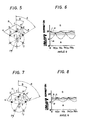
- the maximum range of imbalance correctable in this case is represented by the maximum imbalance correction curve n shown in FIG. 6.
- the region B on the upper side of the curve n is an imbalance non-correctable region in which imbalance can not be corrected by the metal material 8 or the like.
- the region A on the lower side of the curve n is an imbalance correctable region in which imbalance can be corrected by the metal material 8 or the like.
- the curve m shows the imbalance correction curve in which two correcting metal materials are inserted to two openings.
- the curve j shows an imbalance correcting curve in which the weight inserted to one opening is 1 gr, and is represented by the following formular:
- R shows the maximum imbalance correcting line.
- FIG. 7 is a view illustrating a method of correcting imbalance in the case where the number of openings is odd
- the maximum range of imbalance correctable in this case is represented by the maximum imbalance correction curve q shown in FIG. 8.
- the curve p shows the imbalance correction curve in which two correcting metal materials are inserted to two openings.
- the curve k shows an imbalance correcting curve in which the weight inserted to one cpening is 1 gr, and is represented by the following formular:
- the openings 7 provided in the armature core 1 are filled with the metal material 8 or the like to thereby correct imbalance. Therefore, the correction is easily effected, and it is possible to make imbalance correction with high accuracy.
- One-side balancing shown in FIG. 3 and two-side balancing shown in FIG. 4 are both possible. Further, in the conventional method wherein the armature core is partially eliminated, the elimination amount is restricted by the configuration thereof and, therefore, it is not possible to sufficiently correct imbalance of an armature which has a large amount of imbalance. Moreover, on some occasions, noise may be disadvantageously generated when the motor is rotated.
- the above-described conventional method involves extremely low operability.
- the method according to the present invention only requires insertion of the metal material 8 or the like into the openings 7. Further, since the controid position of the matal material 8 or the like is substantially constant and, moreover, the filling amount is easily controlled, it is possible to obtain a vector composition value which corresponds to an imbalance correction amount by a simple calculation. Accordingly, the operability is excellent, and it is possible to effect an imbalance correction with high accuracy.
- the shape of the metal material 8 or the like to be inserted in the openings 7 it is possible to make use of various kinds of shape, such as a rivet shape, a screw shape, a shaft shape, a split pin shape, a bushing shape, a coiled spring shape or a polygonal shape.
- the metal material 8 may be tapered at its end so that its insertability into the openings 7 is improved. Further, the metal material 8 may be formed into the shape of a hook for the purpose of improving the reliability of its fixing.
- the inserting method it is possible to employ various kinds of method, such as press-fitting, caulking, riveting, screwing,-shrink fitting or expansion fitting.
- the material for the filler it is possible to use various kinds of rubber and resin, or a liquid-state non-metallic material according to need in addition to a metal material, such as iron, copper, lead or aluminum.
Landscapes
- Engineering & Computer Science (AREA)
- General Engineering & Computer Science (AREA)
- Physics & Mathematics (AREA)
- Acoustics & Sound (AREA)
- Aviation & Aerospace Engineering (AREA)
- Mechanical Engineering (AREA)
- Power Engineering (AREA)
- Manufacture Of Motors, Generators (AREA)
Abstract
Description
- The present invention relates to an armature for a DC motor. More particularly, the invention pertains to an armature for a DC motor having a structure which is suitable for correcting imbalance which constitues a main cause of vibrations.
- There have heretofore been two methods, that is, the addition method and the removal method, of correcting the imbalance of an armature for an electric motor, as discussed in a publication titled "Method of Balancing Small-Sized Motor Rotor" by Shigesawa, Kawamori and Nakayama, on pp. 173 to 177 in Shimazu Hyoron Vol. 32, No. 2 (1975). In correction by the addition method, which adds such as resin to the outerpheripheral portion of the armature, it is difficult to make adjustment by a minute amount. On the other hand, in correction by the removal method, it is possible to effect a minute adjustment relatively easily. However, when the outer periphery of the armature core is partially eliminated, the air gap defined between the same and the field system is theoretically changed. In consequence, in a permanent magnet type DC motor in particular, the second method of correction definitely involves the disadvantage that a magnetic vibration is easily generated.
- An object of the present invention is to provide an armature for a DC motor which enables easy and highly accurate imbalance correction, is well balanced and further has excellent vibrational characteristics.
- A first feature of the present invention resides in an arrangement wherein two or more imbalance correcting openings are provided in an armature core in parallel to a shaft on a circumference which is concentrical with the shaft, and members serving as weights are inserted in the adjacent openings to thereby correct any imbalance, the number of adjacent openings being selected to be (n-1/2)+1 or less when the number n of openings is odd and to be n/2 or less when the number is even. A second feature of the present invention resides in that at least a part of each of the members inserted in the adjacent openings is eliminated to correct any imbalance in the condition in which the number of adjacent openings is selected in the manner mentioned in the first feature of the present invention.
- According to the imbalance correction of the present invention, the object of the present invention is easily achieved, because the imbalance correction of an armature for D.C. motor can be practiced only by inserting members to the correcting openings, and weight of the inserting members is easily adjustable by lengthening or shortening at least one of the length of the inserting members.
-
- FIG. 1 is a perspective view of one embodiment of the armature for a DC motor according to the present invention,
- FIG. 2 is a sectional perspective view taken along the line X-X of FIG. 1,
- FIGs. 3 and 4 are two embodiments of sectional views an armature core taken along the line Y-Y of FIG. 1,
- FIGs. 5 and 7 are views illustrating methods of correcting imbalance employed in the case in which the number of openings is even and odd, respectively, and
- FIGs. 6 and 8 are views illustrating imbalance correctable regions by the methods shown in FIGs. 5 and 7, respectively.
- Referring to FIGs. 1 and 2 the
reference numeral 1 denotes an armature core; 2 a shaft; 3 a commutator; 4 a coil; and 5 a shaft press-fitting bore formed in thearmature core 1. Two ormore openings 7 with the same cross-sectional configuration are provided between coil-insertingslots 6 and the shaft press-fitting bore 5 in thearmature core 1 in parallel to theshaft 2 in such a manner as to be equally spaced on a circumference which is concentrical with theshaft 2. In FIGs. 7 and 5, 5 and 6 openings with the same cross-sectional configuration are provided. Theopenings 7 are employed to correct imbalance of the armature. It is possible for theopenings 7 to be easily machined at the same time as when thearmature core 1 is blanked by a press, before theshaft 2 is press-fitted into thearmature core 1. - - Referring to FIGs. 3 and 4, the
openings 7 provided as above are filled with, for example, ametal material 8 to correct imbalance of the armature. FIG. 3 shows how imbalance is corrected when the points of imbalance are concentrated on the center of thearmature core 1 between A and B which are side plain surfaces thereof. In this case, themetal material 8 is inserted in the central portion of theopening 7 as illustrated. On the other hand, FIG. 4 shows the way in which imbalance is corrected when the points of imbalance are concentrated on both the A and B sides of thearmature core 1. In FIG. 4, ametal material 8a and ametal material 8b are respectively inserted on the A side of one opening and the B side of anotheropening 7 in the manner that the composed weight center of thematerials materials metal material 8 or the like in accordance with the amount of imbalance. - However, the amount of the
metal material 8 or the like which can be inserted in eachopening 7 is restricted by the configuration of theopening 7. For this reason, the imbalance correction amount in the case when only one portion of eachopening 7 is utilized is smaller than a value obtained by dividing the product of the weight of themetal material 8 and the distance D/2 between the central position of themetal material 8 and the center of theshaft 2 by the distance L between the central position of imbalance and the center of theshaft 2. It is to be noted that the cross-sectional area of eachopening 7 is restricted by the configuration, magnetic properties and mechanical strength of thearmature core 1 and therefore cannot be sharply increased. Accordingly, among theopenings 7, a plurality ofopenings 7 which permit vector composition are filled with themetal material 8 or the like to thereby correct imbalance, whereby a large degree of imbalance may be corrected. - Incidentally, when the number n of
openings 7 is odd, the maximum value N of the number ofopenings 7 which permit vector composition is as follows:
- On the other hand, when the number n is even, the number N is as follows:

openings 7, those which are respectively located at points f, g and h are filled with a proper amount of themetal material 8 which is decided by the following formular (3) or (4), so that it is possible for vectors to be combined at a point P' as a force couple, whereby it is possible to correct both the imbalance amount and the imbalance position (the angle 6) with high accuracy. The maximum range of imbalance correctable in this case is represented by the maximum imbalance correction curve n shown in FIG. 6. The region B on the upper side of the curve n is an imbalance non-correctable region in which imbalance can not be corrected by themetal material 8 or the like. The region A on the lower side of the curve n is an imbalance correctable region in which imbalance can be corrected by themetal material 8 or the like. The curve m shows the imbalance correction curve in which two correcting metal materials are inserted to two openings. The curve j shows an imbalance correcting curve in which the weight inserted to one opening is 1 gr, and is represented by the following formular:
- where S: the imbalance correction amount (gr)
- M: weight of one inserting material (gr)
- 1: the distance between the center of the
shaft 2 and the center of the opening 7 - R shows the maximum imbalance correcting line.
- FIG. 7 is a view illustrating a method of correcting imbalance in the case where the number of openings is odd, while FIG. 8 is a graph illustrating an imbalance correctable region, which exemplarily shows the case where n = 5. In a manner similar to the above, when points of imbalance are concentrated on the point P, among the
openings 7, those which are respectively located at points f', g' and h' are filled with a proper amount of themetal material 8 or the like so that it is possible for vectors to be combined at the point P' as a force couple, thus enabling correction of the imbalance. The maximum range of imbalance correctable in this case is represented by the maximum imbalance correction curve q shown in FIG. 8. The curve p shows the imbalance correction curve in which two correcting metal materials are inserted to two openings. The curve k shows an imbalance correcting curve in which the weight inserted to one cpening is 1 gr, and is represented by the following formular: -

- According to the above-described embodiment of the present invention, the
openings 7 provided in thearmature core 1 are filled with themetal material 8 or the like to thereby correct imbalance. Therefore, the correction is easily effected, and it is possible to make imbalance correction with high accuracy. One-side balancing shown in FIG. 3 and two-side balancing shown in FIG. 4 are both possible. Further, in the conventional method wherein the armature core is partially eliminated, the elimination amount is restricted by the configuration thereof and, therefore, it is not possible to sufficiently correct imbalance of an armature which has a large amount of imbalance. Moreover, on some occasions, noise may be disadvantageously generated when the motor is rotated. In addition, in the case of a DC motor which employs a permanent magnet as a field system, the range of application of which has been enlarged these days, if thearmature core 1 is sharply cut off, the air gap between the same and the field system is made nonuniform, which fact involves a risk of generating a magnetic vibration. According to the embodiment of the present invention, imbalance is corrected by making use of theopenings 7 which are provided between the slot seat and the shaft press-fitting bore 5 of thearmature core 1. Therefore, there is no effect on the magnetic properties. Moreover, by increasinc the cross-sectional area of each of theopenings 7, it is possible to increase the imbalance correctable amount and to make imbalance correction without damaging the outer peripheral portion of thearmature core 1. Further, according to the conventional method wherein a resin or the like is added to the outer peripheral portion of the armature, it is common to attach the resin on the coil.4 between thearmature 1 and thecommutator 3. It is, however, difficult to attach an amount of resin which corresponds to an amount of imbalance and to make uniform the distance between the centroid position of the resin attached and the axis of the armature, without any variation. In general, therefore, it is common to first effect a rough correction as a primary correction and then to make a secondary correction in which thearmature core 1 is partially eliminated so that imbalance is corrected within a predetermined accuracy range. Further, it may be necessary to bind the resin or the like added to the imbalance portion by a tape so that the resin is prevented from coming off during rotation at high speed. Thus, the above-described conventional method involves extremely low operability. On the other hand, the method according to the present invention only requires insertion of themetal material 8 or the like into theopenings 7. Further, since the controid position of thematal material 8 or the like is substantially constant and, moreover, the filling amount is easily controlled, it is possible to obtain a vector composition value which corresponds to an imbalance correction amount by a simple calculation. Accordingly, the operability is excellent, and it is possible to effect an imbalance correction with high accuracy. - Additionally, as regards the shape of the
metal material 8 or the like to be inserted in theopenings 7, it is possible to make use of various kinds of shape, such as a rivet shape, a screw shape, a shaft shape, a split pin shape, a bushing shape, a coiled spring shape or a polygonal shape. Moreover, themetal material 8 may be tapered at its end so that its insertability into theopenings 7 is improved. Further, themetal material 8 may be formed into the shape of a hook for the purpose of improving the reliability of its fixing. On the other hand, as to the inserting method, it is possible to employ various kinds of method, such as press-fitting, caulking, riveting, screwing,-shrink fitting or expansion fitting. As the material for the filler, it is possible to use various kinds of rubber and resin, or a liquid-state non-metallic material according to need in addition to a metal material, such as iron, copper, lead or aluminum. - It is to be noted that, although, in the above-described embodiment, the
openings 7 have previously been provided and are filled with themetal material 8 or the like to thereby make an imbalance correction, the arrangement may be such that the whole of the inside of all theopenings 7 have previously been filled with an easily workable member, such as a resin or lead, and imbalance is corrected by partially eliminating the filler. By this arrangement, it is possible to obtain the same effect as that offered by the above-described embodiment. It is to be noted that, in such a case also, a technique similar to those shown in FIGs.5 and 7 may, as a matter of course, be employed to increase the imbalance correction amount.
Claims (7)
characterized in that two or more imbalance correcting openings (7) are provided in said armature core (1) in parallel to said shaft (2) such as to be on a circumference which is concentrical with said shaft (2), and members (8) serving as weights respectively inserted in adjacent ones of the openings (7), the number of the adjacent openings being selected to be (n-1/2)+1 or less when the total number n of the openings (7) is odd and to be n/2 or less when the total number n is even, whereby any balance is corrected.
characterized in that the openings (7) have the same cross-sectional configuration. -
characterized in that the openings (7) are arranged to, be equally spaced on the circumference being concentrical with the shaft (2).
characterized in that each of the openings has a circular cross-sectional configuration and is provided between the circumference surface of said armature core and a shaft press-fitting bore (5) of said armature core (1).
characterized in that, when the points of imbalance are concentrated on the center of said armature core (1), said members (8) are inserted in the central portion of said openings (7).
characterized in that, when the points of imbalance are concentrated near the both side plain surfaces of said armature core, said members are respectively inserted near the one plain surface of one opening and the other plain surface of another opening, and each member is arranged in the manner that the composed weight center of said members is arranged to be on the same plain containing each weight center of said members.
characterized in that at least one of said members (8) is inserted to said opening (7) after said member is eliminated partially.
Applications Claiming Priority (2)
| Application Number | Priority Date | Filing Date | Title |
|---|---|---|---|
| JP146545/84 | 1984-07-13 | ||
| JP59146545A JPH0652984B2 (en) | 1984-07-13 | 1984-07-13 | Armature for DC motor |
Publications (3)
| Publication Number | Publication Date |
|---|---|
| EP0168055A2 true EP0168055A2 (en) | 1986-01-15 |
| EP0168055A3 EP0168055A3 (en) | 1987-04-01 |
| EP0168055B1 EP0168055B1 (en) | 1990-11-14 |
Family
ID=15410073
Family Applications (1)
| Application Number | Title | Priority Date | Filing Date |
|---|---|---|---|
| EP85108707A Expired - Lifetime EP0168055B1 (en) | 1984-07-13 | 1985-07-12 | Armature for direct current motor |
Country Status (4)
| Country | Link |
|---|---|
| US (1) | US4644201A (en) |
| EP (1) | EP0168055B1 (en) |
| JP (1) | JPH0652984B2 (en) |
| DE (1) | DE3580528D1 (en) |
Cited By (5)
| Publication number | Priority date | Publication date | Assignee | Title |
|---|---|---|---|---|
| GB2251131A (en) * | 1990-12-21 | 1992-06-24 | Johnson Electric Sa | Balancing armature of an electric motor |
| US5251833A (en) * | 1990-11-08 | 1993-10-12 | Asmo Co., Ltd. | Method of winding armature of electric rotating machine |
| CN1077346C (en) * | 1995-08-10 | 2002-01-02 | 三菱电机株式会社 | Armature core of DC motor |
| WO2009036023A3 (en) * | 2007-09-12 | 2009-04-30 | Canopy Technologies Llc | Method of balancing an embedded permanent magnet motor rotor |
| WO2014060339A3 (en) * | 2012-10-15 | 2014-09-25 | Continental Automotive Gmbh | Rotor assembly for an electric machine and method for producing a rotor assembly |
Families Citing this family (21)
| Publication number | Priority date | Publication date | Assignee | Title |
|---|---|---|---|---|
| US5319844A (en) | 1985-12-23 | 1994-06-14 | Unique Mobility, Inc. | Method of making an electromagnetic transducer |
| MX161230A (en) | 1985-12-23 | 1990-08-24 | Unique Mobility Inc | IMPROVEMENTS IN LIGHTWEIGHT ELECTROMAGNETIC TRANSDUCER |
| DE3924715A1 (en) * | 1989-07-26 | 1991-02-07 | Mtu Muenchen Gmbh | DEVICE FOR UNBALANCE COMPENSATION ON A RADIAL COMPRESSOR ROTOR |
| JPH06205564A (en) * | 1992-10-01 | 1994-07-22 | Tokyo Parts Ind Co Ltd | Vibration motor without eccentric weight |
| EP0660491B1 (en) * | 1993-12-24 | 1997-03-05 | Nippondenso Co., Ltd. | Motor for electric pumps |
| US6226857B1 (en) * | 1998-03-20 | 2001-05-08 | Axis Usa, Inc. | Methods for balancing electric motors |
| JP4306062B2 (en) * | 1999-03-10 | 2009-07-29 | 株式会社デンソー | How to correct armature balance |
| DE10044484A1 (en) * | 2000-09-08 | 2002-03-21 | Bosch Gmbh Robert | fan |
| JP3621929B2 (en) * | 2002-04-18 | 2005-02-23 | ファナック株式会社 | Electric motor and manufacturing method thereof |
| DE102005030716A1 (en) * | 2005-07-01 | 2007-01-04 | Arnold Umformtechnik Gmbh & Co.Kg | balance weight |
| US7342331B2 (en) * | 2005-10-25 | 2008-03-11 | Honeywell International, Inc. | Multi-plane flexible rotor balancing |
| TWI348258B (en) * | 2006-11-10 | 2011-09-01 | Ind Tech Res Inst | A motor mechanism of dc frequency conversion of compressor |
| CN101192766B (en) * | 2006-11-22 | 2010-04-21 | 财团法人工业技术研究院 | Motor mechanism of DC frequency conversion compressor |
| JP5170878B2 (en) * | 2008-03-12 | 2013-03-27 | アイチエレック株式会社 | Permanent magnet rotating machine rotor |
| TWM354274U (en) * | 2008-11-07 | 2009-04-01 | Risun Expanse Corp | Vibration-adjustable miniature vibration motor |
| DE102010041599A1 (en) * | 2010-09-29 | 2012-03-29 | Robert Bosch Gmbh | Balanced rotor for a rotary machine and method for balancing a rotor |
| EP2947765B1 (en) | 2014-05-20 | 2020-08-26 | Black & Decker Inc. | Electronic braking for a universal motor in a power tool |
| US11047528B2 (en) | 2016-02-12 | 2021-06-29 | Black & Decker Inc. | Electronic braking for a power tool having a brushless motor |
| JP6143314B1 (en) * | 2016-07-29 | 2017-06-07 | パナソニック アプライアンシズ リフリジレーション デヴァイシズ シンガポール | Hermetic refrigerant compressor and refrigeration system |
| CN110383637A (en) * | 2017-03-03 | 2019-10-25 | 通用电气再生能源技术公司 | Salient pole motor |
| CN110662902B (en) * | 2017-05-23 | 2022-03-25 | 松下电器制冷装置新加坡 | Hermetic refrigeration compressors and refrigeration units |
Family Cites Families (9)
| Publication number | Priority date | Publication date | Assignee | Title |
|---|---|---|---|---|
| DE585457C (en) * | 1933-10-04 | Viktor Blaess | Device for the mass balancing of wave elastic bodies | |
| US861463A (en) * | 1907-01-31 | 1907-07-30 | Oscar H Hyde | Balancing emery-wheels and similar devices. |
| US2336697A (en) * | 1940-10-03 | 1943-12-14 | Knapp Monarch Co | Fan balancing means |
| FR1280370A (en) * | 1961-02-14 | 1961-12-29 | Bbc Brown Boveri & Cie | Rotor of an electric machine with balancing weights capable of being displaced in the longitudinal direction |
| GB1125151A (en) * | 1964-09-16 | 1968-08-28 | Nat Res Dev | Correction balancing of rotating bodies |
| AT300096B (en) * | 1970-02-20 | 1972-07-10 | Interelectric Ag | Balanced rotor winding for electrical machines |
| US3838464A (en) * | 1972-10-24 | 1974-09-24 | Nashua Corp | Retaining ring for magnetic disc pack assembly |
| DE2346345A1 (en) * | 1973-09-14 | 1975-03-27 | Bosch Gmbh Robert | Injection moulded skin-casing for FHP motor laminated rotor - has axially parallel holes around circumference for balancing-weights |
| US4535373A (en) * | 1980-12-29 | 1985-08-13 | Papst-Motoren Gmbh & Co. Kg | Labyrinth seal in disk storage drive |
-
1984
- 1984-07-13 JP JP59146545A patent/JPH0652984B2/en not_active Expired - Fee Related
-
1985
- 1985-07-12 DE DE8585108707T patent/DE3580528D1/en not_active Expired - Lifetime
- 1985-07-12 EP EP85108707A patent/EP0168055B1/en not_active Expired - Lifetime
- 1985-07-15 US US06/754,926 patent/US4644201A/en not_active Expired - Lifetime
Cited By (7)
| Publication number | Priority date | Publication date | Assignee | Title |
|---|---|---|---|---|
| US5251833A (en) * | 1990-11-08 | 1993-10-12 | Asmo Co., Ltd. | Method of winding armature of electric rotating machine |
| GB2251131A (en) * | 1990-12-21 | 1992-06-24 | Johnson Electric Sa | Balancing armature of an electric motor |
| CN1077346C (en) * | 1995-08-10 | 2002-01-02 | 三菱电机株式会社 | Armature core of DC motor |
| WO2009036023A3 (en) * | 2007-09-12 | 2009-04-30 | Canopy Technologies Llc | Method of balancing an embedded permanent magnet motor rotor |
| US7626309B2 (en) | 2007-09-12 | 2009-12-01 | Canopy Technologies, Llc | Method of balancing an embedded permanent magnet motor rotor |
| WO2014060339A3 (en) * | 2012-10-15 | 2014-09-25 | Continental Automotive Gmbh | Rotor assembly for an electric machine and method for producing a rotor assembly |
| US9948161B2 (en) | 2012-10-15 | 2018-04-17 | Continental Automotive Gmbh | Rotor assembly for an electric machine and method for producing a rotor assembly |
Also Published As
| Publication number | Publication date |
|---|---|
| DE3580528D1 (en) | 1990-12-20 |
| EP0168055A3 (en) | 1987-04-01 |
| US4644201A (en) | 1987-02-17 |
| JPS6126454A (en) | 1986-02-05 |
| JPH0652984B2 (en) | 1994-07-06 |
| EP0168055B1 (en) | 1990-11-14 |
Similar Documents
| Publication | Publication Date | Title |
|---|---|---|
| EP0168055B1 (en) | Armature for direct current motor | |
| CN108933495B (en) | Motor with a stator having a stator core | |
| US5175461A (en) | Permanent magnet rotor having magnet positioning and retaining means | |
| US5237737A (en) | Method of making a permanent magnet rotor | |
| US4003265A (en) | Mass balancing system for rotatable assemblies | |
| US5345669A (en) | Method of making a permanent magnet rotor | |
| US3264880A (en) | Gyros with compensated flexure pivots | |
| EP0484953B1 (en) | Method of winding armature of electric rotating machine | |
| US4531071A (en) | Rotor assembly | |
| US5789832A (en) | Alternator rotor shaft | |
| DE20300056U1 (en) | Actuator for the bias magnet of a spindle motor | |
| US4812692A (en) | Motor | |
| US6452299B2 (en) | Motor having a plain bearing for adjusting an axial play of a rotor shaft and associated method therefor | |
| US3445702A (en) | Dynamoelectric machine stator yoke with keyed salient poles | |
| US4837472A (en) | Inner magnet rotor for magnet pump | |
| US5550417A (en) | Amortisseur winding arrangement, in a rotor for electrical, rotating equipment | |
| EP0959365B1 (en) | MRI shimset and gradient coil with cutout portions formed therein | |
| JP7431664B2 (en) | rotor of rotating electric machine | |
| WO2021157061A1 (en) | Rotary electric machine | |
| JPH05316672A (en) | Rotor of motor for compressor | |
| JPH05328645A (en) | Rotor of motor for compressor | |
| JP7465717B2 (en) | Rotor of rotating electrical machine | |
| US5319274A (en) | Magnetic bearings with twisted laminations | |
| JPH05146102A (en) | Permanent magnet rotor | |
| EP4535624A1 (en) | Motor frame and motor device |
Legal Events
| Date | Code | Title | Description |
|---|---|---|---|
| PUAI | Public reference made under article 153(3) epc to a published international application that has entered the european phase |
Free format text: ORIGINAL CODE: 0009012 |
|
| AK | Designated contracting states |
Designated state(s): CH DE FR GB IT LI NL SE |
|
| PUAL | Search report despatched |
Free format text: ORIGINAL CODE: 0009013 |
|
| AK | Designated contracting states |
Kind code of ref document: A3 Designated state(s): CH DE FR GB IT LI NL SE |
|
| 17P | Request for examination filed |
Effective date: 19870403 |
|
| 17Q | First examination report despatched |
Effective date: 19890118 |
|
| RBV | Designated contracting states (corrected) |
Designated state(s): DE FR GB IT |
|
| GRAA | (expected) grant |
Free format text: ORIGINAL CODE: 0009210 |
|
| AK | Designated contracting states |
Kind code of ref document: B1 Designated state(s): DE FR GB IT |
|
| REF | Corresponds to: |
Ref document number: 3580528 Country of ref document: DE Date of ref document: 19901220 |
|
| ET | Fr: translation filed | ||
| ITF | It: translation for a ep patent filed | ||
| ITTA | It: last paid annual fee | ||
| PLBE | No opposition filed within time limit |
Free format text: ORIGINAL CODE: 0009261 |
|
| STAA | Information on the status of an ep patent application or granted ep patent |
Free format text: STATUS: NO OPPOSITION FILED WITHIN TIME LIMIT |
|
| 26N | No opposition filed | ||
| REG | Reference to a national code |
Ref country code: GB Ref legal event code: IF02 |
|
| PGFP | Annual fee paid to national office [announced via postgrant information from national office to epo] |
Ref country code: FR Payment date: 20030620 Year of fee payment: 19 |
|
| PGFP | Annual fee paid to national office [announced via postgrant information from national office to epo] |
Ref country code: GB Payment date: 20030623 Year of fee payment: 19 |
|
| PGFP | Annual fee paid to national office [announced via postgrant information from national office to epo] |
Ref country code: DE Payment date: 20030908 Year of fee payment: 19 |
|
| PG25 | Lapsed in a contracting state [announced via postgrant information from national office to epo] |
Ref country code: GB Free format text: LAPSE BECAUSE OF NON-PAYMENT OF DUE FEES Effective date: 20040712 |
|
| PG25 | Lapsed in a contracting state [announced via postgrant information from national office to epo] |
Ref country code: DE Free format text: LAPSE BECAUSE OF NON-PAYMENT OF DUE FEES Effective date: 20050201 |
|
| GBPC | Gb: european patent ceased through non-payment of renewal fee |
Effective date: 20040712 |
|
| PG25 | Lapsed in a contracting state [announced via postgrant information from national office to epo] |
Ref country code: FR Free format text: LAPSE BECAUSE OF NON-PAYMENT OF DUE FEES Effective date: 20050331 |
|
| REG | Reference to a national code |
Ref country code: FR Ref legal event code: ST |