EP0167018B1 - Web fed die cutting press having automatic 3-axis die registration system - Google Patents
Web fed die cutting press having automatic 3-axis die registration system Download PDFInfo
- Publication number
- EP0167018B1 EP0167018B1 EP85107085A EP85107085A EP0167018B1 EP 0167018 B1 EP0167018 B1 EP 0167018B1 EP 85107085 A EP85107085 A EP 85107085A EP 85107085 A EP85107085 A EP 85107085A EP 0167018 B1 EP0167018 B1 EP 0167018B1
- Authority
- EP
- European Patent Office
- Prior art keywords
- web
- die
- die unit
- press
- work station
- Prior art date
- Legal status (The legal status is an assumption and is not a legal conclusion. Google has not performed a legal analysis and makes no representation as to the accuracy of the status listed.)
- Expired
Links
- 238000005520 cutting process Methods 0.000 title claims description 35
- 239000000835 fiber Substances 0.000 claims description 23
- 239000000463 material Substances 0.000 claims description 14
- 239000003365 glass fiber Substances 0.000 claims description 10
- 238000012545 processing Methods 0.000 claims description 10
- 230000000694 effects Effects 0.000 claims description 6
- 238000006073 displacement reaction Methods 0.000 claims description 3
- 230000007246 mechanism Effects 0.000 description 15
- 230000000875 corresponding effect Effects 0.000 description 9
- 238000010586 diagram Methods 0.000 description 5
- 235000012431 wafers Nutrition 0.000 description 5
- 238000013461 design Methods 0.000 description 4
- 238000000034 method Methods 0.000 description 3
- 230000003287 optical effect Effects 0.000 description 3
- 230000004044 response Effects 0.000 description 3
- 230000001276 controlling effect Effects 0.000 description 2
- 238000004519 manufacturing process Methods 0.000 description 2
- 239000002184 metal Substances 0.000 description 2
- 238000004080 punching Methods 0.000 description 2
- 239000004065 semiconductor Substances 0.000 description 2
- 125000006850 spacer group Chemical group 0.000 description 2
- 238000013459 approach Methods 0.000 description 1
- 230000000712 assembly Effects 0.000 description 1
- 238000000429 assembly Methods 0.000 description 1
- 230000005540 biological transmission Effects 0.000 description 1
- 238000004891 communication Methods 0.000 description 1
- 230000002596 correlated effect Effects 0.000 description 1
- 230000009849 deactivation Effects 0.000 description 1
- 230000001419 dependent effect Effects 0.000 description 1
- 238000004049 embossing Methods 0.000 description 1
- 239000004744 fabric Substances 0.000 description 1
- 230000000977 initiatory effect Effects 0.000 description 1
- 230000001788 irregular Effects 0.000 description 1
- 238000012544 monitoring process Methods 0.000 description 1
- 230000008569 process Effects 0.000 description 1
- 230000000284 resting effect Effects 0.000 description 1
- 238000009958 sewing Methods 0.000 description 1
Images


Classifications
-
- B—PERFORMING OPERATIONS; TRANSPORTING
- B26—HAND CUTTING TOOLS; CUTTING; SEVERING
- B26D—CUTTING; DETAILS COMMON TO MACHINES FOR PERFORATING, PUNCHING, CUTTING-OUT, STAMPING-OUT OR SEVERING
- B26D7/00—Details of apparatus for cutting, cutting-out, stamping-out, punching, perforating, or severing by means other than cutting
- B26D7/01—Means for holding or positioning work
- B26D7/015—Means for holding or positioning work for sheet material or piles of sheets
-
- B—PERFORMING OPERATIONS; TRANSPORTING
- B26—HAND CUTTING TOOLS; CUTTING; SEVERING
- B26D—CUTTING; DETAILS COMMON TO MACHINES FOR PERFORATING, PUNCHING, CUTTING-OUT, STAMPING-OUT OR SEVERING
- B26D7/00—Details of apparatus for cutting, cutting-out, stamping-out, punching, perforating, or severing by means other than cutting
- B26D7/26—Means for mounting or adjusting the cutting member; Means for adjusting the stroke of the cutting member
- B26D7/2628—Means for adjusting the position of the cutting member
-
- B—PERFORMING OPERATIONS; TRANSPORTING
- B26—HAND CUTTING TOOLS; CUTTING; SEVERING
- B26F—PERFORATING; PUNCHING; CUTTING-OUT; STAMPING-OUT; SEVERING BY MEANS OTHER THAN CUTTING
- B26F1/00—Perforating; Punching; Cutting-out; Stamping-out; Apparatus therefor
- B26F1/38—Cutting-out; Stamping-out
- B26F1/40—Cutting-out; Stamping-out using a press, e.g. of the ram type
-
- Y—GENERAL TAGGING OF NEW TECHNOLOGICAL DEVELOPMENTS; GENERAL TAGGING OF CROSS-SECTIONAL TECHNOLOGIES SPANNING OVER SEVERAL SECTIONS OF THE IPC; TECHNICAL SUBJECTS COVERED BY FORMER USPC CROSS-REFERENCE ART COLLECTIONS [XRACs] AND DIGESTS
- Y10—TECHNICAL SUBJECTS COVERED BY FORMER USPC
- Y10T—TECHNICAL SUBJECTS COVERED BY FORMER US CLASSIFICATION
- Y10T83/00—Cutting
- Y10T83/162—With control means responsive to replaceable or selectable information program
- Y10T83/173—Arithmetically determined program
- Y10T83/175—With condition sensor
- Y10T83/178—Responsive to work
-
- Y—GENERAL TAGGING OF NEW TECHNOLOGICAL DEVELOPMENTS; GENERAL TAGGING OF CROSS-SECTIONAL TECHNOLOGIES SPANNING OVER SEVERAL SECTIONS OF THE IPC; TECHNICAL SUBJECTS COVERED BY FORMER USPC CROSS-REFERENCE ART COLLECTIONS [XRACs] AND DIGESTS
- Y10—TECHNICAL SUBJECTS COVERED BY FORMER USPC
- Y10T—TECHNICAL SUBJECTS COVERED BY FORMER US CLASSIFICATION
- Y10T83/00—Cutting
- Y10T83/444—Tool engages work during dwell of intermittent workfeed
- Y10T83/4458—Work-sensing means to control work-moving or work-stopping means
-
- Y—GENERAL TAGGING OF NEW TECHNOLOGICAL DEVELOPMENTS; GENERAL TAGGING OF CROSS-SECTIONAL TECHNOLOGIES SPANNING OVER SEVERAL SECTIONS OF THE IPC; TECHNICAL SUBJECTS COVERED BY FORMER USPC CROSS-REFERENCE ART COLLECTIONS [XRACs] AND DIGESTS
- Y10—TECHNICAL SUBJECTS COVERED BY FORMER USPC
- Y10T—TECHNICAL SUBJECTS COVERED BY FORMER US CLASSIFICATION
- Y10T83/00—Cutting
- Y10T83/444—Tool engages work during dwell of intermittent workfeed
- Y10T83/4458—Work-sensing means to control work-moving or work-stopping means
- Y10T83/446—With means to initiate tool feed by same control impulse
-
- Y—GENERAL TAGGING OF NEW TECHNOLOGICAL DEVELOPMENTS; GENERAL TAGGING OF CROSS-SECTIONAL TECHNOLOGIES SPANNING OVER SEVERAL SECTIONS OF THE IPC; TECHNICAL SUBJECTS COVERED BY FORMER USPC CROSS-REFERENCE ART COLLECTIONS [XRACs] AND DIGESTS
- Y10—TECHNICAL SUBJECTS COVERED BY FORMER USPC
- Y10T—TECHNICAL SUBJECTS COVERED BY FORMER US CLASSIFICATION
- Y10T83/00—Cutting
- Y10T83/444—Tool engages work during dwell of intermittent workfeed
- Y10T83/4564—With means to produce plurality of work-feed increments per tool cycle
- Y10T83/4567—Including supplemental work-feed means
-
- Y—GENERAL TAGGING OF NEW TECHNOLOGICAL DEVELOPMENTS; GENERAL TAGGING OF CROSS-SECTIONAL TECHNOLOGIES SPANNING OVER SEVERAL SECTIONS OF THE IPC; TECHNICAL SUBJECTS COVERED BY FORMER USPC CROSS-REFERENCE ART COLLECTIONS [XRACs] AND DIGESTS
- Y10—TECHNICAL SUBJECTS COVERED BY FORMER USPC
- Y10T—TECHNICAL SUBJECTS COVERED BY FORMER US CLASSIFICATION
- Y10T83/00—Cutting
- Y10T83/525—Operation controlled by detector means responsive to work
- Y10T83/533—With photo-electric work-sensing means
-
- Y—GENERAL TAGGING OF NEW TECHNOLOGICAL DEVELOPMENTS; GENERAL TAGGING OF CROSS-SECTIONAL TECHNOLOGIES SPANNING OVER SEVERAL SECTIONS OF THE IPC; TECHNICAL SUBJECTS COVERED BY FORMER USPC CROSS-REFERENCE ART COLLECTIONS [XRACs] AND DIGESTS
- Y10—TECHNICAL SUBJECTS COVERED BY FORMER USPC
- Y10T—TECHNICAL SUBJECTS COVERED BY FORMER US CLASSIFICATION
- Y10T83/00—Cutting
- Y10T83/525—Operation controlled by detector means responsive to work
- Y10T83/536—Movement of work controlled
-
- Y—GENERAL TAGGING OF NEW TECHNOLOGICAL DEVELOPMENTS; GENERAL TAGGING OF CROSS-SECTIONAL TECHNOLOGIES SPANNING OVER SEVERAL SECTIONS OF THE IPC; TECHNICAL SUBJECTS COVERED BY FORMER USPC CROSS-REFERENCE ART COLLECTIONS [XRACs] AND DIGESTS
- Y10—TECHNICAL SUBJECTS COVERED BY FORMER USPC
- Y10T—TECHNICAL SUBJECTS COVERED BY FORMER US CLASSIFICATION
- Y10T83/00—Cutting
- Y10T83/525—Operation controlled by detector means responsive to work
- Y10T83/538—Positioning of tool controlled
-
- Y—GENERAL TAGGING OF NEW TECHNOLOGICAL DEVELOPMENTS; GENERAL TAGGING OF CROSS-SECTIONAL TECHNOLOGIES SPANNING OVER SEVERAL SECTIONS OF THE IPC; TECHNICAL SUBJECTS COVERED BY FORMER USPC CROSS-REFERENCE ART COLLECTIONS [XRACs] AND DIGESTS
- Y10—TECHNICAL SUBJECTS COVERED BY FORMER USPC
- Y10T—TECHNICAL SUBJECTS COVERED BY FORMER US CLASSIFICATION
- Y10T83/00—Cutting
- Y10T83/525—Operation controlled by detector means responsive to work
- Y10T83/541—Actuation of tool controlled in response to work-sensing means
- Y10T83/543—Sensing means responsive to work indicium or irregularity
Definitions
- This invention relates to a web fed die cutting press having a reciprocable ram wherein the web is incrementally shifted to bring each area of the web to be die cut to a work station and mechanism is provided for bringing the web longitudinally thereof along what may be called the X axis into alignment with indicium on the web, for rotating the die unit about an axis defined as 8, and for shifting the die unit laterally of the web along a Y axis to assure precise registration of the die unit with an area of the web to be die cut, before the ram is shifted to effect die cutting of the defined area of the web.
- the prior art has not provided efficient die cutting presses which are effective to align a die unit with a defined area of web to be die cut on an extremely precise basis without sacrifice in the speed of operation of the press, while at the same affording essentially automatic operation.
- Die cut presses have heretofore been provided which in effect constitute sheet fed units with alignment indicia being read by sensor mechanism forming a part of the press and wherein the work sheet is shifted as required to bring an image thereon into proper registration with the die assembly.
- this is not a desirable mode of operation, especially where the die cut areas of the web are to be knocked out at a station spaced from and independent of the work station of the die cut press.
- Registration assemblies have also heretofore been provided for controlling the positioning of webs, but these mechanisms have not incorporated interrelated components for effecting registration on X, Y and 8 axes.
- fiber optics and photocells are used to sense marks on a web in the form of a transverse bar and an angled bar, but the assembly cannot provide accurate positioning of a die unit as accomplished in the present invention because of lack of provision for rotation of the die unit about the 8 axis while maintaining the image area of the web to be die cut in proper alignment with a die cut unit.
- Patent US-A-3,758,784 discloses an optical detecting head where a line or edge sensor depends on the provision of fiber optics and four photocells are arranged in a line transverse to an article mark or edge being sensed to indicate the location of the article relative to the sensor. This is an example of accurate registration mark sensing but not exemplary of article and die registration combining shifting of a web, and shifting and rotation of the die.
- Patent US-A-4,151,451 functions to control X and Y axes movement of a work piece carrying table which are shifted by respective servo-motors. Indicia on the work piece are appropriately sensed and the signals resulting therefrom employed to control shifting of the table. Movement of the tool is possible but no rotation of a die unit or the like in coordination with longitudinal shifting of the work piece was contemplated by the inventor.
- Fiber optic position sensing and recording mechanism is set out in Patent US-A-3,658,430 but the signals produced are not used to adjust the disposition of a work piece.
- Patent US-A-3,385,245 embodies photocell position sensing to control longitudinal advancement of a web.
- Four photocells spaced around a sewing machine needle sense the edge of the cloth to provide digital control signals which are connected to stepping motors that move a table carrying the work piece. Adjustment of the table is possible along X and Y axes. No rotation of a tool about a ⁇ axis is provided.
- Patents US-A-2,002,374 and US-A-4,085,928 illustrate the use of photocell sensing (and in the case of the '928 patent the provision of fiber optics) of markings on a moving work piece to actuate a machine tool as in the'374 patent or a folding mechanism as in the '928 patent.
- Patent No. 4,109,158 suggests the use of photocells for controlling positioning of a flexible printed circuit board carrying work piece. Alignment of the board with a mask is accomplished by photocell sensing of light through X-axis extended and Y-axis extended slots as contrasted with sensing of imprinted markings. There is no teaching of X, Y and 8 axes alignment of a die unit with images on a web to be die cut.
- Patent US-A-4,089,242 discloses a method and apparatus for forming gaskets and the like which is capable of operating at faster speeds than die cut presses theretofor available but the unit does not have X, Y and 8 axes registration of a die unit with preprinted images or other predetermined areas of the web to be successively die cut.
- EP-A-0 109 101 pertains to a die cutter adapted to sever opaque documents that are carried between two transparent web plies, wherein lateral and pivotal positioning of the die cutter relative to the opaque documents at the cutting zone is not initiated until the web has ceased advancement.
- the punch of the die cutter has slits that enable light directed through the web from a single, stationary source to pass toward photo cells.
- This type of apparatus greater accuracy of alignment of the die cutter to the web is attained when the slits are narrowed, but unfortunately as the slit is narrowed, less light passes therethrough thereby increasing the difficulty of accurately determining the presence of light.
- this type of apparatus is primarily useful only for severing opaque documents from a transparent web. The preamble of claim 1 is based on this document.
- the invention relates to a die cutting press for web material having indicia on opposite longitudinally extending sides thereof associated with each defined area of the web to be die cut, the indicia on the web which are related to a particular defined web area each being provided with a segment which extends transversely of the web and at least one of the related indicia having a section disposed longitudinally of the web, said press including: a base platen defining a web material work station; means for mounting a die unit on the base platen below said power operated means in disposition for rotation about an upright axis and shifting of the die unit in a direction at least transversely of the path of travel of a web through the press; means for effecting rotation of the die unit on said base platen; power operated means shiftable toward and away from said platen; web backup means carried by the power operated means cooperable with the die unit to present a web processing work station therebetween; means for shifting the die unit transversely of an area of the web situated at said press work station; means for feeding the web material on an incremental
- the precision of registration at high operating speeds is maintained by a unique combination of fiber optics, photoelectronics and microproces- sing.
- the system is capable of automatically aligning images on a web with the die unit to a tolerance of ⁇ 0,013 mm.
- Press 20 includes a base platen 22 carried by a horizontal support member 24 forming a part of the overall machine.
- base platen 22 is of relatively thick metal stock that serves as a die unit carrier operable to process a web 26 ( Figure 3) fed to the press.
- web is used generically to define any length of material having more than one image thereon to be successively subjected to a die cutting operation. This would include therefore, rolls of material as well as sheet stack having more than one image in successive order.
- Upstanding rods 28 project upwardly from respective corners of platen 22 and support an upper frame assembly 30.
- Ram platen 32 recip- rocably carried by rods 28 below assembly 30 depends from a piston 34 of piston and cylinder assembly 38 located vertically in frame assembly 30.
- a micrometer unit 36 mounted on the top of assembly 30 and operably joined to the piston and cylinder assembly 38 permits selective adjustment of the length of stroke of rod 34 and thereby the extent of vertical shifting of the ram platen 32. It is to be understood in this respect that suitable bearings 40 secured to ram 32 and surrounding rods 28 restrict reciprocation of the ram 32 to a vertical path of travel while the undersurface of such ram remains in a horizontal position.
- the die unit broadly designated 42 and made up of a die assembly and a punch assembly defining a press work station is shiftably positioned on and carried by the base platen 22.
- the lower plate 44 of die unit 42 is directly engageable with the upper surface of base platen 22 while an upper plate 46 is mounted directly above plate 44.
- a pair of end spacers 48 cooperate with blocks 50 at opposite sides of the die unit 42 to provide support for die holder 52.
- the die assembly 54 is mounted directly on the die holder 52.
- the punch holder 56 yieldably supported on die holder 52 by a series of corner located pin and spring guide means 58 carries a punch assembly 60 on the underside thereof.
- the dies used in press 20 should be of the independent free floating type which have their own interval springs to return the punch holder 56 after the blanking operation. It is to be noted that no part of the die unit 42 is affixed to the ram 32 of the press 20 which functions solely as a force transmission device.
- the web infeed mechanism 62 shown on the left-hand side of the press 20 as depicted in Figure 1 includes a pair of upright stanchions 64 which carry a horizontal support plate 66. Bearers 68 at opposite ends of mechanism 62 support two pairs of horizontally spaced, vertically aligned infeed rollers, the first vertical pair being designated 70a and 70b while the second vertical pair are 70c and 70d respectively.
- the lower roller 70b is driven directly by a DC powered, X-axis servo-motor 72 carried by the bearer 68a while the adjacent lower roller 70d is rotated at the same speed through the medium of a timing belt therebetween within the housing of bearer 68a. It can be seen from Figure 1 that the nip between rollers 70a and 70b is horizontally aligned with the nip between the rollers 70c and 70d.
- the web outfeed end of press 20 has web drive mechanism 74 which is identical with infeed mechanism 62 and thus need not be described in detail although it is to be understood that the DC X-axis servo-motor 76 is wired in parallel with motor 72. Consequently, the lower driven rollers 78a and 78c are caused to rotate at the same speed as rollers 78b and 78d. Similarly, the nips between rollers 78a and 78b and between rollers 78c and 78d are horizontally aligned with the nips between rollers 70a and 70b as well as 70c and 70d. Thus, the path of travel of web 26 through press 20 as shown in Figure 1 is essentially along horizontal line 80.
- the lower plate 44 along with the upper plate 46 secured thereto function as a bolster for supporting the die assembly of the press.
- the base platen 22 has a central rectangular opening 82 therein oriented with the longest axis thereof transverse of press 20.
- a channel-shaped block element 84 supported on the upper surface of member 24 within opening 82 through the medium of a spacer 86 has a frustoconical groove 88 therein which extends transversely of press 20.
- a slide 90 complementally positioned in groove 88 of channel block element 84 supports a rotatable support member 92 secured directly to the underside of lower plate 44 (see Figure 5).
- the support member 92 is rotatable with respect to the underlying block 90 through the medium of pivot mechanism 94.
- mechanism 94 is the fact that the bearing forming a part thereof allows support member 92 and thereby the components resting thereon (upper and lower plates 44, 46, holder 52 and die assembly 54 and punch assembly 56 carried thereby) to shift vertically through a limited displacement (in the order of 1/32 inch) without permitting the components carried by such rotatable mechanism to shift laterally.
- Lower plate 44 has two spaced, rectangular openings 96 therein which clear corresponding rectangular air bearings 98 oriented with the series of air outlet ports thereof disposed downwardly in facing relationship to the upper surface of platen 22.
- Useful air bearings in this respect have been found to be those sold by C & H Precision Tool, Inc., Long Island, New York under the trade designation "Flying Carpet", Model B.
- the air supply conduit 100 for bearings 98 is illustrated in Figure 4 and is threaded into a suitable port in plate 44 which communicates with tubing 102 recessed in plate 44 and in parallel communication with the inlets 104 of each of the bearings 98.
- the air bearings 98 are secured by pins 106 to the upper plate 46 to maintain each of the bearings in proper spatial disposition within corresponding rectangular openings 96. It is to be understood in this respect that the downwardly facing airbleed orifices in the bottom surfaces of bearings 98 are of relatively small diameter and serve to create a relatively uniform layer of air between respective bearings and the upper face of platen 22 when air control means is actuated to allow air under pressure to be directed to the bearings.
- Means for effecting shifting movement of the block 90 in the channel-shaped groove 88 includes a Y-axis DC servo-motor 108 ( Figures 1, 2, 4 and 5) mounted on the outer face of platen 22 through the medium of a hollow mounting block 110 in disposition such that the output shaft 108a thereof is directly aligned with the block 90.
- Shaft 112 extending through a suitable passage therefor in the platen 22 is joined to the outer end of motor shaft 108a for rotation thereby.
- the innermost end of shaft 112 is coupled to a lead screw 114 threaded into slide block 90. Operation of motor 108 effects rotation of shaft 112 and thereby lead screw 114 connected thereto to shift slide 90 in channel block 84 depending upon the direction of rotation of the motor 108.
- FIG. 1 Another DC servo-motor 116 referred to as the 8 axis motor and carried by platen 22 adjacent Y-axis motor 108 is supported by an L bracket 118 pivotally connected to an extension 120 projecting from a side face of platen 22. It is apparent from Figures 1 and 4 that bracket 118 and thereby the motor 116 mounted thereon are pivotal about the axis of upright pin 122.
- the shaft 124 of motor 116 threaded in the outer end thereof, is threadably received within pivot block 126 rotatably carried by U bracket 128 oriented with the legs thereof facing outwardly as depicted in Figures 1-5.
- the bight portion of U bracket 128 is secured to plates 44 and 46 so that upon rotation of shaft 124 by motor 116, die unit 42 is rotated about an upright axis through rotatable support member 92.
- First and second sensing means are provided in association with the die unit 42 and include first and second sensors 130 and 132 respectively as shown by dashed lines in Figure 3.
- the sensor 132 is located to the left of the web 26 as the latter moves left to right of Figure 1 and from the top to the bottom of the drawings of Figures 12-15 inclusive while sensor 130 is on the right side of the web.
- Each of the sensors 130 is made up of a metal block 134 supported by a bracket 136 in turn carried by a corresponding face of lower die assembly 54.
- the block 134 is adjustably mounted on a respective bracket 136, or in the alternative, the bracket with a corresponding block 134 thereon is adjustably secured to a respective surface of assembly 54.
- each block 134 serves as a support for four sets of fiber optic bundles 140, 142, 144 and 146.
- the bundles 140 and 142 form one associated pair while bundles 144 and 146 define a second associated pair.
- the exposed end of fiber optic bundle 140 illustrated in Figure 9 is strategically located relative to the exposed end of fiber optic bundle 142 such that a line therebetween is intended to be essentially parallel to the longitudinal length of web 26 travelling through press 20.
- a line between the exposed ends of bundles 144 and 146 is perpendicular to the line between bundles 140 and 142 and the ends of bundles 144 and 146 are located inboard of the exposed ends of bundles 140 and 142.
- a series of flexible light transmitting glass fibers make up each of the bundles 140-146 inclusive. Certain of such glass fibers act as light transmitters leading from a light source 148 located remotely of the die assembly to each of the exposed ends of bundles 140-146 inclusive. Certain other glass fibers of each bundle function as light receptors leading from the exposed ends thereof to light responsive means in the nature of phototransistors 150, 152, 154 and 156 operably associated with respective bundles 140-146 respectively.
- Sensor 132 is similar to the sensor 130 except that it does not include fiber optic bundles equivalent to 144 and 146. Accordingly, the sensor 132 has only fiber optic bundles 140 and 142 leading to associated phototransistors such as 150 and 152, although it is to be understood in this respect that certain of the glass fibers making up the bundles 140 and 142 of sensor 132 do extend from light source 148 to the exposed ends of such bundles.
- the phototransistors 150-156 inclusive are joined to a suitably programmed microprocessor which receives inputs from such phototransistors and issues appropriate commands to the servo-motors 72, 76, 108 and 116.
- the flow diagram of Figure 16 indicates generally a suitable program sequence for the microprocessor with it being understood in this respect that the specific nature of such program may be varied depending upon an operator's processing requirements and the type of material being processed. Thus, the flow diagram of Figure 16 is representative of an operable program and is not intended to be construed literally as the only sequence of operations which may be carried out to accomplish alignment of a defined work area of a web with the die unit 42 on an incremental basis.
- Press 20 is especially useful for processing a web 26 having a series of images or other defined areas thereon which are to be subjected to a processing operation at the work station of the press presented by the die unit 42.
- die cutting as used herein is intended to be construed generically and to encompass various types of web processing operations which are referred to in various art recognized terms, including but not limited to stamping, cutting, punching, piercing, blanking embossing and other equivalent procedures.
- Web 26 preferably has a pair of indicium 158 and 160 associated with each defined area of the web to be processed.
- web 26 has been illustrated in Figure 8 as having a series of images 166 thereon which define the outline of the area to be subjected to a processing operation.
- the design illustrated is for exemplary purposes only and that many diverse shapes may be suitably processed in press 20 using a particular die shape for the web images to be processed.
- the image 166 is typical of many designs in that it has a perimeter of irregular configuration which requires very precise alignment of the die with the edge of the design.
- the image to be die cut often has a series of internally located zones to be subjected to the die cutting operation including holes, slots, and larger irregularly configured areas which are to be stamped, cut, punched or embossed.
- Figure 7 schematically illustrates a circuit board having slots to be die cut which are indicated by the numeral 168. Holes to be punched out for example may be of the shape denoted by the numeral 170. An irregularly shaped aperture requiring die cutting is indicated by numeral 172. Relatively small holes such as 174 and 176 respectively also require punching. In all instances, alignment of the die assembly with the portions of the image 166 to be subjected to the die cutting operation must be carried out on an extremely precise basis and preferably within a tolerance of ⁇ 0.0005 inch.
- each of the indicium 158 and 160 is of generally T-shaped configuration as best shown in Figure 10.
- each indicium it is not necessary that each indicium be T-shaped; a right angle design is useful.
- a T-shape is preferred since web 26 need not be run through the press 20 in a prescribed relationship in the sense of right or left-hand edges respectively.
- indicia other than relatively opaque marks may be used for registration purposes. Slits or holes in the web may be employed with a light source above or below the openings and sensors positioned on the opposite side of the web.
- each of the T-shaped indicium has a section 162 extending longitudinally of the web 26 as well as a transversely extending segment 164.
- Each of the segments 164 is located equidistantly of the ends of a corresponding section 162 and desirably, the length of each segment 164 from the outer extremity thereof to the point of joinder of such segment with section 162 is equal to the distance from a respective end of section 162 to the point of joinder thereof with segment 164.
- the effective width of each segment 164 and associated section 162 is correlated with the distance between the center points of the exposed ends of the photooptical bundles 140-146 inclusive.
- the distance between opposed margins 164a and 164b of the section 164 is equal to the distance between the center points of the exposed ends of bundles 140 and 142.
- the space between the margins 162a and 162b of section 162 of indicium 160 is equal to the distance between the center points of the exposed ends of fiber optic bundles 144 and 146.
- the exposed ends of fiber optic bundles 140, 142 as well as 144 and 146 are located a distance such that when the bundles 144 and 146 are aligned with a section 162 in disposition such that the latter underlies an equal area of such bundles, the exposed ends of bundles 140 and 142 are located a distance from section 162 approximately one-half of a segment 164.
- Web 26 is fed to press 20 by suitable supply means and introduced into the nip between respective pairs of vertically aligned infeed rollers 70a-70d inclusive.
- the material is then passed between die assembly 54 and the overlying punch assembly 56.
- the portion of the web 26 which has been subjected to processing at the work station is then removed therefrom via the outfeed web drive mechanism 74 with the web passing between the nips of corresponding pairs of vertically aligned rollers 78a-78d inclusive.
- the microprocessor control of press 20 first causes the servo-drive motors 72 and 76 to operate simultaneously to move the web 26 through a given increment of travel to bring the next image 166 to be processed to the work station of the press defined by the space between die assembly 54 and punch assembly 56.
- the movement of the web during this time increment is relatively rapid with the fast operation of the drive motors 72 and 76 being discontinued after the next to be processed image 166 approaches a position in substantial alignment with the die assembly 54.
- Initial setup of the machine involves programming the microprocessor (which is accomplished by a digital keyboard forming a part of the control panel of the machine) to adjust the length of time motors 72 and 76 are actuated in the full speed mode as a function of the size of the images 166 and the relative spacing therebetween as found on a particular web 26. After the web material 26 is fed a given amount adequate to bring the indicia 158 and 160 of the next to be processed image 166 into proximal relationship to sensors 130 and 132, motors 72 and 76 are then controlled by the microprocessor to operate in what may be best defined as a creep mode.
- the microprocessor in this instance causes the motors 72 and 76 to be incrementally actuated in a stepping fashion to move the web through successive discrete increments of 0.0005 inch. Creep of the web 26 is continued until a sensor 130 or 132 first detects a segment 164 of one of the indicium 158 or 160.
- the schematic representation indicates that the sensor 132 first senses the presence of segment 164 of indicium 158 on the left-hand side of web 26 as the latter moves upwardly in the depiction of Figure 12.
- the voltage level output of phototransistor 150 to the microprocessor is a function of and varies with the amount of light reflected back from the web 26 via glass fiber bundle 140.
- the creep mode initiation causes the microprocessor to enter a prescribed alignment portion of the software program which not only causes air to be directed to the bolster air bearings 98 at a prescribed time but also continues the creep mode of the motors 72 and 76 until one of the T-shaped indicia 158 or 160 is sensed by corresponding sensor 130 or 132.
- the first phase of the alignment program involves a determination as to whether or not the amount of light reflected and sensed by the phototransistors 150 associated with sensors 130 and 132 is the same and of a maximum amount for the particular web being processed.
- the motors 72 and 76 continue their creep mode advancement of 0.0005 inch steps. However, as soon as a segment 164 of one of the indicium 158 and 160 moves into disposition such that it is sensed by a bundle 140 and indicated schematically as being the left indicium 158 in Figure 12, the amount of light reflected to an associated phototransistor 150 is less than had previously been seen by such component thus changing its voltage input to the microprocessor.
- the press operator first determines the amount of light reflected from the background of the web and then causes one of the sensors 130 or 132 to read the amount of light reflected from a registration mark 158 or 160. From these readings, the microprocessor determines a so-called threshold level for that particular job.
- the threshold is computed by the microprocessor to be 80% of the difference between the amount of light reflected from a material's background as compared with the amount of light reflected from a registration mark alone.
- the program sequence of the microcomputer continues the step by step forward advancement of DC motors 72 and 76.
- the reflectance levels sensed by phototransistors 150 associated with sensors 130 and 132 are designated as +X1 and +X2, respectively, while the reflectance levels sensed by the receptors of the trailing optical bundles 142 of sensors 130 and 132 are designated by the notations -X1 and -X2.
- DC motors 72 and 76 incrementally advance the web 26 along the so-called X axis extending longitudinally of the web until there is an indication that the reflectance levels of +X1 and +X2 are both more than threshold values. If the answer to this interrogation is yes, the microcomputer leapfrogs to another downline step of the programming sequence. However, if the answer to whether or not both +X1 and +X2 reflectance levels are more than threshold is no, then the next step in the interrogation is whether or not the +X1 reflectance level is greater than threshold.
- the microprocessor then actuates the 8 DC stepper motor 116 causing the latter to advance in a clockwise direction.
- the die assembly 54 is rotated by motor 116 to pivot the die unit 42, now supported by a layer of air .001 to .003 inch thick between air bearings 98 and the underlying platen 22, and thereby in effect move the receptor 140 of sensor 130 toward the adjacent segment 164 of indicia 160.
- the microprocessor program is of the well-known loop nature such that clockwise rotation of the 8 stepper motor 116 continues until microprocessor interrogation indicates that the reflectance levels X1 and X2 are both more than threshold.
- the 8 stepper motor 116 is incrementally rotated in a counterclockwise direction to rotate the die unit 42 about an upright axis therethrough until such time as the microcomputer senses that both +X1 and +X2 reflectance levels are more than threshold.
- microcomputer next determines whether or not +X1 equals -X1 or +X2 equals -X2. If the response amounts to a no answer, then the microcomputer causes the X-axis stepper motors 72 and 76 to advance one step. This loop is continued until the microcomputer finds that the reflectance levels of +X1 equals -X1 or the reflectance level of +X2 equals the reflectance of -X2.
- This step in the program is required to maintain the bundle receptor of the sensor 130 or 132 which first determines the presence of an indicium 158 or 160 in sensing relationship with such indicium as the die unit 42 is rotated about the 8 axis by DC 8 stepper motor 116.
- the microprocessor program determines that the reflectance level of +X1 equals the reflectance level -Xl or the reflectance level of +X2 equals the reflectance level -X2, then the next determination is whether the reflectance level of +X1 equals the reflectance level of -X1 and the reflectance level of +X2 equals the reflectance level of -X2.
- the next step in the programming sequence is a search for whether or not the reflectance level of +X1 equals the reflectance level of -X1. If the answer is no, the 6 stepper motor 116 is actuated to rotate the shaft 124 in a clockwise direction with advancement of the web by the X-axis stepper motors 72 and 76 being effected as necessary to maintain the sensor which first senses an indicium 158 or 160 in sensing relationship thereto as previously described.
- the interrogation by the microprocessor as to whether or not the reflectance level of +X1 equals -X1 is a yes answer, than the 8-axis stepper motor 116 is actuated to cause the shaft 124 to rotate in a counterclockwise direction.
- the programming loop includes a sequential determination as to whether or not the reflectance level of +X1 equals the reflectance level of -X1 or the reflectance level of +X2 equals the reflectance level of -X2. If not, the X-axis stepper motors 72 and 76 are actuated as previously indicated to advance the web and maintain the sensor which first senses an indicium 158 or 160 in sensing relationship thereto.
- the next step is a determination as to whether or not the reflectance level of +Y equals the reflectance level of -Y. This is indicated by the schematic depiction of Figure 14.
- the next step in the programming sequence is to determine whether or not the indicium 158 and 160 are in proper relationship to die unit 42 in a direction transverse of web 26. For clarity purposes, this is indicated in Figure 14 as a determination of the location of receptor fibers of bundles 144 and 146 connected to phototransistors 154 and 156 respectively relative to the elongated section 162 of a respective T-shaped indicium 158 and 160.
- the sensor 130 is assumed to be the one having Y-axis sensing bundles 144 and 146 but such bundles could be provided on both of the sensors, or on the other sensor 132 if desired.
- the section 162 is of such length that the Y-axis receptors of bundles 144 and 146 are located to determine the presence of section 162 when the receptors of bundles 140 of sensors 130 or 132 first sense the presence of a transversely extending segment 164 of indicium 158 and 160.
- the reference indicia 158 and 160 could be right angle markings rather than of T-shaped configuration, the use of T-shaped markings permit the press operator to put the web 26 in the press without regard for a left or right side.
- the first microprocessor interrogation of phototransistors 154 and 156 is whether or not the reflectance level of + Y (sensed by the fiber receptors of bundle 144) equals a reflectance level of -Y (sensed by the receptor fibers of bundle 146). If the answer to this interrogation is a no, then the next program interrogation is whether or not the reflectance level of +Y is greater than the reflectance level of -Y.
- the Y-axis stepper motor 108 is actuated to rotate the shaft 112 thereof in a direction to move the block 90 and thereby die unit 42 connected thereto one step inwardly.
- the loop is continued until such time as the microprocessor determines that the reflectance level of +Y equal the reflectance level of -Y.
- stepper motor 108 is actuated to rotate shaft 112 in a direction to move the block 90 and associated die unit 42 one step in.
- the loop is repeated as previously described until the microprocessor program determines that the +Y reflectance level is equal to the -Y reflectance level as illustrated in Figure 15, whereupon the microprocessor returns to its main program resulting in deactivation of air delivery to the air bearings 98 and operation of the piston and cylinder assembly 38 to bring the die assembly 54 into functional engagement with web 26.
- an alternate sensor 130a is depicted which differs from the sensor 130 for example in the provision of photoelectrical devices 178a-d inclusive which are carried by the underside of the block 138 in disposition to sense the presence of an indicium 158 or 160 in a manner similar to the operation of sensors 130 and 132 along with associated phototransistors 150-156 inclusive.
- photoelectric devices 178a-d inclusive a remote light source and phototransistors receiving light inputs from glass fiber bundles is avoided by placement of the light emitting devices and light sensors directly in the sensing head itself for positioning in close proximity to the web 26 as the latter moves through the work station of press 20.
- the same sensing of the presence of a mark may be carried out as previously described using essentially the same program for the microprocessor control.
Landscapes
- Life Sciences & Earth Sciences (AREA)
- Forests & Forestry (AREA)
- Engineering & Computer Science (AREA)
- Mechanical Engineering (AREA)
- Perforating, Stamping-Out Or Severing By Means Other Than Cutting (AREA)
- Details Of Cutting Devices (AREA)
- Punching Or Piercing (AREA)
Description
- This invention relates to a web fed die cutting press having a reciprocable ram wherein the web is incrementally shifted to bring each area of the web to be die cut to a work station and mechanism is provided for bringing the web longitudinally thereof along what may be called the X axis into alignment with indicium on the web, for rotating the die unit about an axis defined as 8, and for shifting the die unit laterally of the web along a Y axis to assure precise registration of the die unit with an area of the web to be die cut, before the ram is shifted to effect die cutting of the defined area of the web.
- The prior art has not provided efficient die cutting presses which are effective to align a die unit with a defined area of web to be die cut on an extremely precise basis without sacrifice in the speed of operation of the press, while at the same affording essentially automatic operation.
- Die cut presses have heretofore been provided which in effect constitute sheet fed units with alignment indicia being read by sensor mechanism forming a part of the press and wherein the work sheet is shifted as required to bring an image thereon into proper registration with the die assembly. As can be appreciated though, it is usually not feasible to shift a web located at the work station of the die cut press in order to bring an image on the web into alignment with the die cut unit without first severing the area of the web next to be die cut from the web itself. For various reasons, this is not a desirable mode of operation, especially where the die cut areas of the web are to be knocked out at a station spaced from and independent of the work station of the die cut press.
- It is also known to provide positioning systems which sense the disposition of an article relative to a sensor which are functional to very accurately locate the work piece with respect to two coordinate axes. For example, in the Heinz Patent US-A-3,207,904, an electro-optical positioning system is disclosed which is capable of providing both translational and rotational positioning of an article. The system is especially useful for positioning semi-conductor wafers during production of transistors where bonding of conductive leads to the wafer must be carried out on an extremely accurate basis. However, the Heinz system is not practical for accurate positioning of images to be die cut forming a part of an elongated web, absent severing of the individual image sections from the web prior to die cut thereof.
- Registration assemblies have also heretofore been provided for controlling the positioning of webs, but these mechanisms have not incorporated interrelated components for effecting registration on X, Y and 8 axes. In Patent US-A-3,919,561, fiber optics and photocells are used to sense marks on a web in the form of a transverse bar and an angled bar, but the assembly cannot provide accurate positioning of a die unit as accomplished in the present invention because of lack of provision for rotation of the die unit about the 8 axis while maintaining the image area of the web to be die cut in proper alignment with a die cut unit.
- Another optical readout system is disclosed for example in Patent US-A-4,059,841 which uses four photocells in a square pattern to read information recorded as marks along a track but here again the system is not operable to register images on a web to be die cut by a combination of web movement and die unit rotation and lateral shifting to obtain precise registration of the die unit with the web before die cutting thereof.
- Patent US-A-3,758,784 discloses an optical detecting head where a line or edge sensor depends on the provision of fiber optics and four photocells are arranged in a line transverse to an article mark or edge being sensed to indicate the location of the article relative to the sensor. This is an example of accurate registration mark sensing but not exemplary of article and die registration combining shifting of a web, and shifting and rotation of the die.
- An automatic positioning system is shown in Patent US-A-4,151,451 which functions to control X and Y axes movement of a work piece carrying table which are shifted by respective servo-motors. Indicia on the work piece are appropriately sensed and the signals resulting therefrom employed to control shifting of the table. Movement of the tool is possible but no rotation of a die unit or the like in coordination with longitudinal shifting of the work piece was contemplated by the inventor.
- Fiber optic position sensing and recording mechanism is set out in Patent US-A-3,658,430 but the signals produced are not used to adjust the disposition of a work piece.
- Patent US-A-3,385,245 embodies photocell position sensing to control longitudinal advancement of a web. Four photocells spaced around a sewing machine needle sense the edge of the cloth to provide digital control signals which are connected to stepping motors that move a table carrying the work piece. Adjustment of the table is possible along X and Y axes. No rotation of a tool about a θ axis is provided.
- Patents US-A-2,002,374 and US-A-4,085,928 illustrate the use of photocell sensing (and in the case of the '928 patent the provision of fiber optics) of markings on a moving work piece to actuate a machine tool as in the'374 patent or a folding mechanism as in the '928 patent.
- One patent which illustrates the use of photocell sensing generally, and in some instances with associated fiber optics, for lateral guidance of travelling webs in response to the sensing of either the edge of a web or a line or marks therealong is: US-A-2,078,669.
- The use of guide or registration marks for the alignment of a mask with a work piece, such as in the manufacture of integrated circuits is disclosed in Patent US-A-3,497,705.
- Patent No. 4,109,158 suggests the use of photocells for controlling positioning of a flexible printed circuit board carrying work piece. Alignment of the board with a mask is accomplished by photocell sensing of light through X-axis extended and Y-axis extended slots as contrasted with sensing of imprinted markings. There is no teaching of X, Y and 8 axes alignment of a die unit with images on a web to be die cut.
- Device which incorporates X and Y axes positioning of relatively movable objects by mechanism which is dependent on photocell sensing of patterns, fiber optic light guides and similar mechanisms is found in Patent US-A-3,385,244.
- Other noteworthy patents include US-A-4,406,949 which suggests apparatus for scanning a work piece for reference points thereon using electronic circuits wherein a laser beam is directed downward onto a wafer containing an integrated circuit die provided with targets which are sensed by the beam to provide die orientation; Patent US-A-4,376,584 wherein a circuit pattern printing system includes alignment apparatus for adjusting a printing mask; Patent US-A-4,053,250 wherein a work table is adjusted by a pneumatic logic circuit; Patent US-A-4,315,201 disclosing apparatus for aligning a mask and wafer each having alignment marks wherein the amount of relative deviation between the alignment marks on the mask and wafer is sensed and a reading effected only after coincidence is photoelectrically detected; Patent US-A-4,354,404, wherein the carriage of a machine tool is movable relative to a work piece by position sensing means; and Patent US-A-4,356,223, wherein a cross-shaped semi-conductor chip registration mark is used for precise positioning of the chip relative to a tool.
- Patent US-A-4,089,242 discloses a method and apparatus for forming gaskets and the like which is capable of operating at faster speeds than die cut presses theretofor available but the unit does not have X, Y and 8 axes registration of a die unit with preprinted images or other predetermined areas of the web to be successively die cut.
- EP-A-0 109 101 pertains to a die cutter adapted to sever opaque documents that are carried between two transparent web plies, wherein lateral and pivotal positioning of the die cutter relative to the opaque documents at the cutting zone is not initiated until the web has ceased advancement. The punch of the die cutter has slits that enable light directed through the web from a single, stationary source to pass toward photo cells. In this type of apparatus, greater accuracy of alignment of the die cutter to the web is attained when the slits are narrowed, but unfortunately as the slit is narrowed, less light passes therethrough thereby increasing the difficulty of accurately determining the presence of light. Moreover, this type of apparatus is primarily useful only for severing opaque documents from a transparent web. The preamble of
claim 1 is based on this document. - The invention relates to a die cutting press for web material having indicia on opposite longitudinally extending sides thereof associated with each defined area of the web to be die cut, the indicia on the web which are related to a particular defined web area each being provided with a segment which extends transversely of the web and at least one of the related indicia having a section disposed longitudinally of the web, said press including: a base platen defining a web material work station; means for mounting a die unit on the base platen below said power operated means in disposition for rotation about an upright axis and shifting of the die unit in a direction at least transversely of the path of travel of a web through the press; means for effecting rotation of the die unit on said base platen; power operated means shiftable toward and away from said platen; web backup means carried by the power operated means cooperable with the die unit to present a web processing work station therebetween; means for shifting the die unit transversely of an area of the web situated at said press work station; means for feeding the web material on an incremental basis to sequentially position successive defined areas of the web at said press work station; sensing means for detecting the arrival of the indicia; means for determining the position of the indicia with respect to the die unit; and means for bringing the die unit into predetermined position with respect to the indicia; the invention is characterized in that said sensing means includes first sensing means movable with the die unit and having sensors positionable to sense the presence of indicia on the web at said work station, said first sensing means being operable to determine the presence of a segment of an indicium which first presents itself to said first sensing means as the web is moved by the feeding means through a displacement to bring the next defined area of the web to said press work station; means controlled by said first sensing means and coupled to said web feeding means and to said die unit rotating means for effecting rotation of the die unit to an extent as may be necessary and in a direction to bring the segment of the other indicium related to the indicium segment first sensed by said first sensing means during movement of a particular defined area of the web to the press work station, into a location where such related segment is sensed as being present by the first sensing means while continuing operation of the web feeding means to move the web longitudinally of the length thereof as may be necessary to maintain the presence sensing relationship between the first sensing means and the segment of the indicium which was first sensed by first sensing means as said next defined area of the web is moved to the press work staiton; said sensing means includes second sensing means movable with the die unit and having sensors positionable to sense the presence and relative position to the second sensing means of the indicium section associated with a respective defined area of the web; and means controlled by said second sensing means and coupled to said die unit shifting means for effecting shifting of the die unit transversely of a respective defined area of the web to an extent as may be necessary to bring the section of a corresponding indicium into predetermined relative relationship to said second sensing means whereby the die unit is accurately positioned with respect to each defined area of the web moved into the press work station; and means for actuating the power operated means only after accurate positioning of a defined area of the web at said press works station has occurred.
- The precision of registration at high operating speeds is maintained by a unique combination of fiber optics, photoelectronics and microproces- sing. In operation, the system is capable of automatically aligning images on a web with the die unit to a tolerance of ±0,013 mm.
-
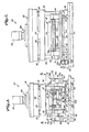
- Figure 1 is a side elevational view of a die cutting press constructed in accordance with the preferred embodiment of the invention and illustrating the platen, a power operated ram, a die unit carried by the ram servo-motors for advancing a web, rotating the die unit and shifting the latter laterally of a web;
- Figure 2 is an end elevational view from the infeed end of the press as illustrated in Figure 1;
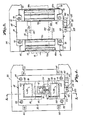
- Figure 3 is a horizontal cross-sectional view taken substantially on the line 3-3 of Figure 1 and illustrating the sensors of the first and second sensing means, as well as the web, in phantom lines;
- Figure 4 is a horizontal cross-sectional view on essentially the same line as 3-3 but with parts being broken away and in section to reveal constructional features of the press;
- Figure 5 is a vertical cross-sectional view on the line 5-5 of Figure 4 and looking in the direction of the arrows;
- Figure 6 is a vertical cross-sectional view on the line 6-6 of Figure 5 and looking in the direction of the arrows;
- Figure 7 is a plan view of a typical part to be die cut from a web processed with the present press and illustrating the complexity often encountered in die cutting operations including exterior and interior lines that must be cut as well as holes, slots and other apertures formed in the part;
- Figure 8 is a fragmentary plan view of a web having images thereon corresponding to that illustrated in detail in Figure 7 and showing T-shaped indicia associated with each of the images to be die cut;
- Figure 9 is a simplified schematic showing of one of the fiber optic and photoelectronic systems embodied in the present press;
- Figure 10 is a fragmentary, enlarged view showing the interrelationship between one of the fiber optic sensors and a T-shaped indicia on the web when the indicia is properly aligned with the sensor;
- Figure 11 is a fragmentary, enlarged view similar to Figure 10 but showing an alternate sensor for determining the presence or absence of a T-shaped indicia on the web as well as the position of such indicia relative to the sensor;
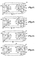
- Figures 12-15 inclusive are schematic illustrations showing the sequence of sensing of T-shaped indicia on a web and the advancement of the web that occurs as well as the rotation and lateral shifting of the die unit effected to bring the die unit and respective associated T-shaped indicia on a web into proper registration with the sensors; and
- Figure 16 is a flow chart illustrating in simplified form the manner in which the microprocessor of the present invention functions to control operation of the web advancement and die unit rotation and shifting servo-motors in response to sensing of the T-shaped indicia on the web to accurately align the die unit with the next to be processed area of the web.
-
Press 20 includes abase platen 22 carried by ahorizontal support member 24 forming a part of the overall machine. As is apparent from Figures 1-3,base platen 22 is of relatively thick metal stock that serves as a die unit carrier operable to process a web 26 (Figure 3) fed to the press. In the context of the present invention, the term web is used generically to define any length of material having more than one image thereon to be successively subjected to a die cutting operation. This would include therefore, rolls of material as well as sheet stack having more than one image in successive order. - Four
upstanding rods 28 project upwardly from respective corners ofplaten 22 and support anupper frame assembly 30.Ram platen 32 recip- rocably carried byrods 28 belowassembly 30 depends from apiston 34 of piston andcylinder assembly 38 located vertically inframe assembly 30. Amicrometer unit 36 mounted on the top ofassembly 30 and operably joined to the piston andcylinder assembly 38 permits selective adjustment of the length of stroke ofrod 34 and thereby the extent of vertical shifting of theram platen 32. It is to be understood in this respect thatsuitable bearings 40 secured to ram 32 and surroundingrods 28 restrict reciprocation of theram 32 to a vertical path of travel while the undersurface of such ram remains in a horizontal position. - The die unit broadly designated 42 and made up of a die assembly and a punch assembly defining a press work station is shiftably positioned on and carried by the
base platen 22. Thelower plate 44 ofdie unit 42 is directly engageable with the upper surface ofbase platen 22 while anupper plate 46 is mounted directly aboveplate 44. As is best evident from Figure 1, a pair ofend spacers 48 cooperate withblocks 50 at opposite sides of thedie unit 42 to provide support fordie holder 52. The die assembly 54 is mounted directly on thedie holder 52. Thepunch holder 56 yieldably supported ondie holder 52 by a series of corner located pin and spring guide means 58 carries a punch assembly 60 on the underside thereof. The dies used inpress 20 should be of the independent free floating type which have their own interval springs to return thepunch holder 56 after the blanking operation. It is to be noted that no part of thedie unit 42 is affixed to theram 32 of thepress 20 which functions solely as a force transmission device. - Viewing Figures 1-3, the
web infeed mechanism 62 shown on the left-hand side of thepress 20 as depicted in Figure 1, includes a pair ofupright stanchions 64 which carry ahorizontal support plate 66.Bearers 68 at opposite ends ofmechanism 62 support two pairs of horizontally spaced, vertically aligned infeed rollers, the first vertical pair being designated 70a and 70b while the second vertical pair are 70c and 70d respectively. Thelower roller 70b is driven directly by a DC powered, X-axis servo-motor 72 carried by thebearer 68a while the adjacentlower roller 70d is rotated at the same speed through the medium of a timing belt therebetween within the housing ofbearer 68a. It can be seen from Figure 1 that the nip betweenrollers rollers - The web outfeed end of
press 20 hasweb drive mechanism 74 which is identical withinfeed mechanism 62 and thus need not be described in detail although it is to be understood that the DC X-axis servo-motor 76 is wired in parallel withmotor 72. Consequently, the lower drivenrollers rollers rollers rollers rollers web 26 throughpress 20 as shown in Figure 1 is essentially alonghorizontal line 80. - It is to be appreciated that the
lower plate 44 along with theupper plate 46 secured thereto function as a bolster for supporting the die assembly of the press. Viewing Figures 4 and 5, it is to be seen that thebase platen 22 has a centralrectangular opening 82 therein oriented with the longest axis thereof transverse ofpress 20. A channel-shapedblock element 84 supported on the upper surface ofmember 24 within opening 82 through the medium of aspacer 86 has afrustoconical groove 88 therein which extends transversely ofpress 20. Aslide 90 complementally positioned ingroove 88 ofchannel block element 84 supports arotatable support member 92 secured directly to the underside of lower plate 44 (see Figure 5). Thesupport member 92 is rotatable with respect to theunderlying block 90 through the medium ofpivot mechanism 94. One feature ofmechanism 94 is the fact that the bearing forming a part thereof allowssupport member 92 and thereby the components resting thereon (upper andlower plates holder 52 and die assembly 54 and punchassembly 56 carried thereby) to shift vertically through a limited displacement (in the order of 1/32 inch) without permitting the components carried by such rotatable mechanism to shift laterally. -
Lower plate 44 has two spaced,rectangular openings 96 therein which clear correspondingrectangular air bearings 98 oriented with the series of air outlet ports thereof disposed downwardly in facing relationship to the upper surface ofplaten 22. Useful air bearings in this respect have been found to be those sold by C & H Precision Tool, Inc., Long Island, New York under the trade designation "Flying Carpet", Model B. Theair supply conduit 100 forbearings 98 is illustrated in Figure 4 and is threaded into a suitable port inplate 44 which communicates withtubing 102 recessed inplate 44 and in parallel communication with theinlets 104 of each of thebearings 98. Theair bearings 98 are secured by pins 106 to theupper plate 46 to maintain each of the bearings in proper spatial disposition within correspondingrectangular openings 96. It is to be understood in this respect that the downwardly facing airbleed orifices in the bottom surfaces ofbearings 98 are of relatively small diameter and serve to create a relatively uniform layer of air between respective bearings and the upper face ofplaten 22 when air control means is actuated to allow air under pressure to be directed to the bearings. - Means for effecting shifting movement of the
block 90 in the channel-shapedgroove 88 includes a Y-axis DC servo-motor 108 (Figures 1, 2, 4 and 5) mounted on the outer face ofplaten 22 through the medium of ahollow mounting block 110 in disposition such that the output shaft 108a thereof is directly aligned with theblock 90.Shaft 112 extending through a suitable passage therefor in theplaten 22 is joined to the outer end of motor shaft 108a for rotation thereby. The innermost end ofshaft 112 is coupled to alead screw 114 threaded intoslide block 90. Operation ofmotor 108 effects rotation ofshaft 112 and therebylead screw 114 connected thereto to shiftslide 90 inchannel block 84 depending upon the direction of rotation of themotor 108. - Another DC servo-
motor 116 referred to as the 8 axis motor and carried by platen 22 adjacent Y-axis motor 108 is supported by anL bracket 118 pivotally connected to anextension 120 projecting from a side face ofplaten 22. It is apparent from Figures 1 and 4 thatbracket 118 and thereby themotor 116 mounted thereon are pivotal about the axis ofupright pin 122. Theshaft 124 ofmotor 116, threaded in the outer end thereof, is threadably received withinpivot block 126 rotatably carried byU bracket 128 oriented with the legs thereof facing outwardly as depicted in Figures 1-5. The bight portion ofU bracket 128 is secured toplates shaft 124 bymotor 116, dieunit 42 is rotated about an upright axis throughrotatable support member 92. - First and second sensing means are provided in association with the
die unit 42 and include first andsecond sensors sensor 132 is located to the left of theweb 26 as the latter moves left to right of Figure 1 and from the top to the bottom of the drawings of Figures 12-15 inclusive whilesensor 130 is on the right side of the web. - Each of the
sensors 130 is made up of ametal block 134 supported by abracket 136 in turn carried by a corresponding face of lower die assembly 54. Desirably, theblock 134 is adjustably mounted on arespective bracket 136, or in the alternative, the bracket with acorresponding block 134 thereon is adjustably secured to a respective surface of assembly 54. - As best shown schematically in Figure 9 depicting
sensor 130, theflat face 138 ofrespective block 134 which normally faces downwardly in proximal relationship to aweb 26 moving alongpath 80, is disposed in essentially a horizontal position. Eachblock 134 serves as a support for four sets of fiber optic bundles 140, 142, 144 and 146. Thebundles bundles fiber optic bundle 140 illustrated in Figure 9 is strategically located relative to the exposed end offiber optic bundle 142 such that a line therebetween is intended to be essentially parallel to the longitudinal length ofweb 26 travelling throughpress 20. Similarly, a line between the exposed ends ofbundles bundles bundles bundles - A series of flexible light transmitting glass fibers make up each of the bundles 140-146 inclusive. Certain of such glass fibers act as light transmitters leading from a
light source 148 located remotely of the die assembly to each of the exposed ends of bundles 140-146 inclusive. Certain other glass fibers of each bundle function as light receptors leading from the exposed ends thereof to light responsive means in the nature ofphototransistors -
Sensor 132 is similar to thesensor 130 except that it does not include fiber optic bundles equivalent to 144 and 146. Accordingly, thesensor 132 has only fiber optic bundles 140 and 142 leading to associated phototransistors such as 150 and 152, although it is to be understood in this respect that certain of the glass fibers making up thebundles sensor 132 do extend fromlight source 148 to the exposed ends of such bundles. - The phototransistors 150-156 inclusive are joined to a suitably programmed microprocessor which receives inputs from such phototransistors and issues appropriate commands to the servo-
motors die unit 42 on an incremental basis. -
Press 20 is especially useful for processing aweb 26 having a series of images or other defined areas thereon which are to be subjected to a processing operation at the work station of the press presented by thedie unit 42. The terminology "die cutting" as used herein is intended to be construed generically and to encompass various types of web processing operations which are referred to in various art recognized terms, including but not limited to stamping, cutting, punching, piercing, blanking embossing and other equivalent procedures. -
Web 26 preferably has a pair ofindicium web 26 has been illustrated in Figure 8 as having a series ofimages 166 thereon which define the outline of the area to be subjected to a processing operation. It is to be appreciated in this respect that the design illustrated is for exemplary purposes only and that many diverse shapes may be suitably processed inpress 20 using a particular die shape for the web images to be processed. However, theimage 166 is typical of many designs in that it has a perimeter of irregular configuration which requires very precise alignment of the die with the edge of the design. Similarly, as shown in Figure 7, the image to be die cut often has a series of internally located zones to be subjected to the die cutting operation including holes, slots, and larger irregularly configured areas which are to be stamped, cut, punched or embossed. Figure 7 schematically illustrates a circuit board having slots to be die cut which are indicated by the numeral 168. Holes to be punched out for example may be of the shape denoted by the numeral 170. An irregularly shaped aperture requiring die cutting is indicated bynumeral 172. Relatively small holes such as 174 and 176 respectively also require punching. In all instances, alignment of the die assembly with the portions of theimage 166 to be subjected to the die cutting operation must be carried out on an extremely precise basis and preferably within a tolerance of ±0.0005 inch. - Desirably, each of the
indicium web 26 need not be run through thepress 20 in a prescribed relationship in the sense of right or left-hand edges respectively. It is also to be understood that indicia other than relatively opaque marks may be used for registration purposes. Slits or holes in the web may be employed with a light source above or below the openings and sensors positioned on the opposite side of the web. - It can be seen from Figure 10 that each of the T-shaped indicium has a
section 162 extending longitudinally of theweb 26 as well as a transversely extendingsegment 164. Each of thesegments 164 is located equidistantly of the ends of acorresponding section 162 and desirably, the length of eachsegment 164 from the outer extremity thereof to the point of joinder of such segment withsection 162 is equal to the distance from a respective end ofsection 162 to the point of joinder thereof withsegment 164. Furthermore, the effective width of eachsegment 164 and associatedsection 162 is correlated with the distance between the center points of the exposed ends of the photooptical bundles 140-146 inclusive. Viewing Figure 10 for example, the distance between opposed margins 164a and 164b of thesection 164 is equal to the distance between the center points of the exposed ends ofbundles margins section 162 ofindicium 160 is equal to the distance between the center points of the exposed ends of fiber optic bundles 144 and 146. Finally, it is to be noted that the exposed ends of fiber optic bundles 140, 142 as well as 144 and 146 are located a distance such that when thebundles section 162 in disposition such that the latter underlies an equal area of such bundles, the exposed ends ofbundles section 162 approximately one-half of asegment 164. -
Web 26 is fed to press 20 by suitable supply means and introduced into the nip between respective pairs of vertically alignedinfeed rollers 70a-70d inclusive. The material is then passed between die assembly 54 and theoverlying punch assembly 56. The portion of theweb 26 which has been subjected to processing at the work station is then removed therefrom via the outfeedweb drive mechanism 74 with the web passing between the nips of corresponding pairs of vertically alignedrollers 78a-78d inclusive. The microprocessor control ofpress 20 first causes the servo-drive motors web 26 through a given increment of travel to bring thenext image 166 to be processed to the work station of the press defined by the space between die assembly 54 and punchassembly 56. The movement of the web during this time increment is relatively rapid with the fast operation of thedrive motors image 166 approaches a position in substantial alignment with the die assembly 54. - Initial setup of the machine involves programming the microprocessor (which is accomplished by a digital keyboard forming a part of the control panel of the machine) to adjust the length of
time motors images 166 and the relative spacing therebetween as found on aparticular web 26. After theweb material 26 is fed a given amount adequate to bring theindicia image 166 into proximal relationship tosensors motors motors web 26 is continued until asensor segment 164 of one of theindicium sensor 132 first senses the presence ofsegment 164 ofindicium 158 on the left-hand side ofweb 26 as the latter moves upwardly in the depiction of Figure 12. As theweb 26 continues its creep mode movement, light transmitted to the surface of theweb 26 by the glass fibers leading fromsource 148 via thebundle 140 ofsensor 132 is reflected from the surface of the web, picked up by receptor fibers of the associatedbundle 140 and transmitted to therespective phototransistor 150. As can be appreciated, the voltage level output ofphototransistor 150 to the microprocessor is a function of and varies with the amount of light reflected back from theweb 26 viaglass fiber bundle 140. - Turning specific attention to the flow chart of Figure 16, it can be seen that the creep mode initiation causes the microprocessor to enter a prescribed alignment portion of the software program which not only causes air to be directed to the bolster
air bearings 98 at a prescribed time but also continues the creep mode of themotors indicia sensor phototransistors 150 associated withsensors motors segment 164 of one of theindicium bundle 140 and indicated schematically as being theleft indicium 158 in Figure 12, the amount of light reflected to an associatedphototransistor 150 is less than had previously been seen by such component thus changing its voltage input to the microprocessor. - It should be explained at this juncture that during setup of the
press 20 for processing each web of material, the press operator first determines the amount of light reflected from the background of the web and then causes one of thesensors registration mark - Returning to the flow diagram of Figure 16, so long as the readings by the
phototransistors 150 connected tobundles 140 ofsensors DC motors phototransistors 150 associated withsensors optical bundles 142 ofsensors phototransistors 150 associated with thesensors DC motors web 26 along the so-called X axis extending longitudinally of the web until there is an indication that the reflectance levels of +X1 and +X2 are both more than threshold values. If the answer to this interrogation is yes, the microcomputer leapfrogs to another downline step of the programming sequence. However, if the answer to whether or not both +X1 and +X2 reflectance levels are more than threshold is no, then the next step in the interrogation is whether or not the +X1 reflectance level is greater than threshold. - If a no answer is in effect received, the microprocessor then actuates the 8
DC stepper motor 116 causing the latter to advance in a clockwise direction. Comparing Figures 12 and 13, it is to be seen from the schematic representation that the die assembly 54 is rotated bymotor 116 to pivot thedie unit 42, now supported by a layer of air .001 to .003 inch thick betweenair bearings 98 and theunderlying platen 22, and thereby in effect move thereceptor 140 ofsensor 130 toward theadjacent segment 164 ofindicia 160. As is evident from the flow diagram of Figure 16, the microprocessor program is of the well-known loop nature such that clockwise rotation of the 8stepper motor 116 continues until microprocessor interrogation indicates that the reflectance levels X1 and X2 are both more than threshold. - Similarly, if microprocessor interrogation as to whether or not the reflectance level of +X1 is greater than threshold in essence establishes what amounts to a yes answer, the 8
stepper motor 116 is incrementally rotated in a counterclockwise direction to rotate thedie unit 42 about an upright axis therethrough until such time as the microcomputer senses that both +X1 and +X2 reflectance levels are more than threshold. - From Figures 1-4 inclusive of the drawings, it can be seen that stepwise rotation of the
shaft 142 of 0stepper motor 116 to rotate theshaft 124 threadably received in theblock 126 which in turn is rotatably carried byU-shaped bracket 128 secured toblocks die unit 42 to be pivoted about the axis ofsupport 92. - Once microprocessor interrogation of
phototransistors X-axis stepper motors sensor indicium die unit 42 is rotated about the 8 axis by DC 8stepper motor 116. It can be seen from Figures 12 and 13 that during rotation of thedie unit 42 about the axis ofsupport 92 by actuation of theDC stepper motor 116, thesensor 132 which first sensedindicium 158 in illustrative Figure 12 would move out of sensing relationship with thesegment 164 ofindicium 158 as the receptor fibers ofbundle 140 ofsensor 130 rotate toward thesegment 164 ofindicium 160, if it were not for the fact that theX-axis stepper motors web 26 in an up direction viewing Figure 12 to maintain the receptor fibers ofbundle 140 ofsensor 132 in sensing relationship with thesegment 164 ofindicium 158. - Once the microprocessor program determines that the reflectance level of +X1 equals the reflectance level -Xl or the reflectance level of +X2 equals the reflectance level -X2, then the next determination is whether the reflectance level of +X1 equals the reflectance level of -X1 and the reflectance level of +X2 equals the reflectance level of -X2.
- Assuming initially that the answer to this microprocessor interrogation is no, the next step in the programming sequence is a search for whether or not the reflectance level of +X1 equals the reflectance level of -X1. If the answer is no, the 6
stepper motor 116 is actuated to rotate theshaft 124 in a clockwise direction with advancement of the web by theX-axis stepper motors indicium - If on the other hand, the interrogation by the microprocessor as to whether or not the reflectance level of +X1 equals -X1 is a yes answer, than the 8-
axis stepper motor 116 is actuated to cause theshaft 124 to rotate in a counterclockwise direction. Here again, the programming loop includes a sequential determination as to whether or not the reflectance level of +X1 equals the reflectance level of -X1 or the reflectance level of +X2 equals the reflectance level of -X2. If not, theX-axis stepper motors indicium - The next step in the programming sequence is to determine whether or not the
indicium unit 42 in a direction transverse ofweb 26. For clarity purposes, this is indicated in Figure 14 as a determination of the location of receptor fibers ofbundles phototransistors elongated section 162 of a respective T-shapedindicium sensor 130 is assumed to be the one having Y-axis sensing bundles 144 and 146 but such bundles could be provided on both of the sensors, or on theother sensor 132 if desired. As previously indicated, thesection 162 is of such length that the Y-axis receptors ofbundles section 162 when the receptors ofbundles 140 ofsensors segment 164 ofindicium reference indicia web 26 in the press without regard for a left or right side. - Viewing Figure 4 and referring as well as to the flow diagram of Figure 16, it is to be seen that the first microprocessor interrogation of
phototransistors axis stepper motor 108 is actuated to rotate theshaft 112 thereof in a direction to move theblock 90 and thereby dieunit 42 connected thereto one step inwardly. The loop is continued until such time as the microprocessor determines that the reflectance level of +Y equal the reflectance level of -Y. - If the interrogation as to whether or not the reflectance level of +Y is greater than the reflectance level of -Y is a no answer, then
stepper motor 108 is actuated to rotateshaft 112 in a direction to move theblock 90 and associated dieunit 42 one step in. The loop is repeated as previously described until the microprocessor program determines that the +Y reflectance level is equal to the -Y reflectance level as illustrated in Figure 15, whereupon the microprocessor returns to its main program resulting in deactivation of air delivery to theair bearings 98 and operation of the piston andcylinder assembly 38 to bring the die assembly 54 into functional engagement withweb 26. - In Figure 11, an
alternate sensor 130a is depicted which differs from thesensor 130 for example in the provision ofphotoelectrical devices 178a-d inclusive which are carried by the underside of theblock 138 in disposition to sense the presence of anindicium sensors photoelectric devices 178a-d inclusive, a remote light source and phototransistors receiving light inputs from glass fiber bundles is avoided by placement of the light emitting devices and light sensors directly in the sensing head itself for positioning in close proximity to theweb 26 as the latter moves through the work station ofpress 20. By positioning thedevices 178a to 178d in a line at a 45° angle with respect to the longitudinal axis ofsection 162 andsegment 164 of theindicium 160, the same sensing of the presence of a mark may be carried out as previously described using essentially the same program for the microprocessor control.
Claims (20)
Applications Claiming Priority (2)
| Application Number | Priority Date | Filing Date | Title |
|---|---|---|---|
| US06/618,421 US4555968A (en) | 1984-06-07 | 1984-06-07 | Web fed die cutting press having automatic 3-axis die registration system |
| US618421 | 1984-06-07 |
Publications (3)
| Publication Number | Publication Date |
|---|---|
| EP0167018A2 EP0167018A2 (en) | 1986-01-08 |
| EP0167018A3 EP0167018A3 (en) | 1986-02-05 |
| EP0167018B1 true EP0167018B1 (en) | 1989-12-06 |
Family
ID=24477600
Family Applications (1)
| Application Number | Title | Priority Date | Filing Date |
|---|---|---|---|
| EP85107085A Expired EP0167018B1 (en) | 1984-06-07 | 1985-06-07 | Web fed die cutting press having automatic 3-axis die registration system |
Country Status (4)
| Country | Link |
|---|---|
| US (1) | US4555968A (en) |
| EP (1) | EP0167018B1 (en) |
| JP (1) | JPS6114896A (en) |
| DE (1) | DE3574574D1 (en) |
Families Citing this family (32)
| Publication number | Priority date | Publication date | Assignee | Title |
|---|---|---|---|---|
| US4817477A (en) * | 1986-12-19 | 1989-04-04 | C.A. Picard, Inc. | Apparatus and method of automatically punching hole patterns in sheets of material |
| EP0367185B1 (en) * | 1988-10-31 | 1994-07-06 | Ushio Co. Limited | Multiple piercing apparatus and method |
| DE4007221A1 (en) * | 1990-03-07 | 1991-09-12 | Gao Ges Automation Org | TEST HEAD FOR CONTACT AREAS OF VALUE CARDS WITH STORED SEMICONDUCTOR CHIP |
| JP2746746B2 (en) * | 1990-11-22 | 1998-05-06 | 大和製罐株式会社 | Intermittent feeder for continuous strip of thin metal plate |
| US5212647A (en) * | 1991-07-15 | 1993-05-18 | Preco Industries, Inc. | Die stamping press having ccd camera system for automatic 3-axis die registration |
| DE4337902C2 (en) * | 1993-11-08 | 1997-01-16 | Kammann Spezialmaschinen Und S | Punch for web material |
| US5685210A (en) * | 1994-02-04 | 1997-11-11 | Ford Motor Company | Apparatus and method for detecting misoriented wheel assemblies |
| US5644979A (en) * | 1996-04-30 | 1997-07-08 | Preco Industries, Inc. | Die cutting and stamping press having simultaneous X, Y, and .O slashed. axes die registration mechanism and method |
| US5777878A (en) * | 1996-06-04 | 1998-07-07 | Preco Industries, Inc. | Screen printing press having longitudinal, lateral and angular screen frame registration system and method |
| GB2343399B (en) * | 1997-03-28 | 2001-04-18 | Preco Ind Inc | Web or sheet-fed apparatus having high-speed positioning mechanism |
| US7640836B1 (en) * | 1997-03-28 | 2010-01-05 | Preco Industries, Inc. | Method for simultaneous x, y and θ registration of segment of continuous web with a processing station |
| US6772661B1 (en) * | 1999-10-04 | 2004-08-10 | Mikkelsen Graphic Engineering | Method and apparatus for precision cutting and the like of graphics areas from sheets |
| JP3473533B2 (en) * | 2000-01-18 | 2003-12-08 | ヤマハ株式会社 | Drilling device and drilling unit used in the drilling device |
| US6546833B1 (en) * | 2000-01-28 | 2003-04-15 | Preco Industries, Inc. | Flexible circuit cutting apparatus and method having indexing and registration mechanism |
| US6672187B2 (en) * | 2001-04-05 | 2004-01-06 | Mikkelsen Graphic Engineering, Inc. | Method and apparatus for rapid precision cutting of graphics areas from sheets |
| US6619167B2 (en) * | 2001-04-05 | 2003-09-16 | Steen Mikkelsen | Method and apparatus for precision cutting of graphics areas from sheets |
| MXPA04012241A (en) * | 2002-06-07 | 2005-02-25 | Interface Inc | Asymmetrical carpet tile design, manufacture and installation. |
| US7311449B2 (en) * | 2002-08-16 | 2007-12-25 | Nanoprecision Products, Inc. | High precision optoelectronic components |
| US7343770B2 (en) | 2002-08-16 | 2008-03-18 | Nanoprecision Products, Inc. | Stamping system for manufacturing high tolerance parts |
| US7140283B2 (en) * | 2004-05-05 | 2006-11-28 | Mikkelsen Graphic Engineering | Automated method and apparatus for vision registration of graphics areas operating from the unprinted side |
| US7260970B2 (en) * | 2004-11-24 | 2007-08-28 | Shun-Lung Chang | Hot forge forming facility |
| US7343858B2 (en) | 2005-04-20 | 2008-03-18 | Preco Industries, Inc | Method for tracking a registered pattern to a continuous web |
| DE102008005214A1 (en) * | 2008-01-18 | 2009-07-23 | Gallus Stanz- Und Druckmaschinen Gmbh | Flatbed punching module for punching a substrate and flatbed punch |
| CN104723403B (en) * | 2015-03-20 | 2017-01-04 | 安徽宏锦包装设备有限公司 | The material cutting means of full-automatic impression mould guillotine |
| CN105856323B (en) * | 2016-06-15 | 2018-01-30 | 昆山鑫泰利精密组件股份有限公司 | A kind of SIM card base guillotine |
| KR102341464B1 (en) * | 2018-05-04 | 2021-12-22 | 주식회사 엘지에너지솔루션 | Cutting device and method for electrode sheet |
| CN109203071A (en) * | 2018-08-24 | 2019-01-15 | 江苏尚唯汽车饰件有限公司 | A kind of automotive trim panel boring device |
| CN112851112B (en) * | 2021-01-19 | 2022-10-28 | 航天特种材料及工艺技术研究所 | Full-automatic fiber material cutting process |
| CN113787570A (en) * | 2021-07-23 | 2021-12-14 | 厦门荣圣兴包装印刷有限公司 | High-efficient full-automatic cross cutting machine |
| US20230079459A1 (en) * | 2021-08-17 | 2023-03-16 | Cymtek Solutions, Inc. | Movable die cutter device |
| CN114524608B (en) * | 2022-03-24 | 2024-03-01 | 石家庄旭新光电科技有限公司 | A high-generation substrate glass cutting control system and control method |
| DE102023111397A1 (en) * | 2023-05-03 | 2024-11-07 | Giesecke+Devrient ePayments GmbH | Method for producing a card element |
Family Cites Families (39)
| Publication number | Priority date | Publication date | Assignee | Title |
|---|---|---|---|---|
| US2002374A (en) * | 1930-03-31 | 1935-05-21 | Gen Electric | Control system |
| US2078669A (en) * | 1931-05-19 | 1937-04-27 | King Andrew | Apparatus for controlling webs |
| US2082634A (en) * | 1936-02-01 | 1937-06-01 | Cameron Machine Co | Electric control system |
| US2777069A (en) * | 1953-03-31 | 1957-01-08 | Olin Mathieson | Web guide control device |
| US2962596A (en) * | 1958-10-01 | 1960-11-29 | Leimer Albert | Control system for the contactless scanning of textile webs and like sheet material |
| US3207904A (en) * | 1962-04-09 | 1965-09-21 | Western Electric Co | Electro-optical article positioning system |
| US3370492A (en) * | 1965-04-02 | 1968-02-27 | Smithe Machine Co Inc F L | Die cutting presses |
| US3385245A (en) * | 1966-10-31 | 1968-05-28 | Her Majesty Underwear Company | Electronic control system for a self-programming sewing machine apparatus |
| US3385244A (en) * | 1966-10-31 | 1968-05-28 | Her Majesty Underwear Company | Electronic control system for automated sewing machine apparatus |
| US3539260A (en) * | 1967-10-02 | 1970-11-10 | Texas Instruments Inc | Method and apparatus for automatic alignment of coherent optical spatial frequency filters |
| US3497705A (en) * | 1968-02-12 | 1970-02-24 | Itek Corp | Mask alignment system using radial patterns and flying spot scanning |
| US3535527A (en) * | 1968-04-26 | 1970-10-20 | North American Rockwell | Digital correlation pattern tracker with single axis scanning |
| FR2105533A5 (en) * | 1970-09-10 | 1972-04-28 | Chambon Automation | |
| US3658430A (en) * | 1970-11-27 | 1972-04-25 | Gaf Corp | Apparatus for detecting, quantizing and displaying the position of registration mark on a sheet |
| US3683195A (en) * | 1971-03-22 | 1972-08-08 | Kasper Instruments | Apparatus for the automatic alignment of two superimposed objects,e.g. a semiconductor wafer and mask |
| US3766355A (en) * | 1971-08-23 | 1973-10-16 | E Kottkamp | Apparatus for use with electron beam welding machines |
| US3758784A (en) * | 1971-10-29 | 1973-09-11 | G Vischulis | Optical detecting head |
| US3796497A (en) * | 1971-12-01 | 1974-03-12 | Ibm | Optical alignment method and apparatus |
| US3868555A (en) * | 1972-01-24 | 1975-02-25 | Instronics Ltd | Line tracing apparatus |
| JPS5136416B2 (en) * | 1972-03-27 | 1976-10-08 | ||
| CH568224A5 (en) * | 1973-04-19 | 1975-10-31 | Zumbach Electronic Automatic | |
| US3840739A (en) * | 1973-08-03 | 1974-10-08 | Gerber Scientific Instr Co | Apparatus and method for tracking a raised edge without shadow interference |
| US3919561A (en) * | 1974-05-28 | 1975-11-11 | Hurletronaltair Inc | Register control scanner assembly and method |
| US3966329A (en) * | 1974-09-24 | 1976-06-29 | Ampex Corporation | Precision optical beam divider and position detector |
| FR2325987A1 (en) * | 1975-09-29 | 1977-04-22 | Thomson Brandt | OPTICAL READING DEVICE FOR A RECORDING |
| US4089242A (en) * | 1975-12-22 | 1978-05-16 | Gramling James T | Method and apparatus for forming gaskets and the like |
| US4085928A (en) * | 1976-01-02 | 1978-04-25 | Arthur Sussman | Folding system with photoelectric detection means |
| DE2601638A1 (en) * | 1976-01-17 | 1977-07-21 | Bosch Gmbh Robert | HANDLING MACHINE |
| GB1520693A (en) * | 1976-04-01 | 1978-08-09 | Crosfield Electronics Ltd | Detecting lateral position of webs |
| US4053250A (en) * | 1976-04-30 | 1977-10-11 | Weatherby & Associates, Inc. | Linear indexer |
| US4109158A (en) * | 1976-05-27 | 1978-08-22 | Western Electric Company, Inc. | Apparatus for positioning a pair of elements into aligned intimate contact |
| JPS5385282A (en) * | 1976-12-30 | 1978-07-27 | Tokyo Kikai Seisakushiyo Kk | Detecting device for position of side edge of running body |
| JPS53111280A (en) * | 1977-03-10 | 1978-09-28 | Canon Inc | Mask or wafer for production of semiconductor elements and device for aligning these |
| IT1165014B (en) * | 1979-03-27 | 1987-04-22 | Innocenti Santeustacchio Spa | GEOMETRIC CONTROL SYSTEM, TO INCREASE THE ACCURACY OF A MACHINE TOOL, PARTICULARLY OF A LARGE DIMENSION MACHINE TOOL |
| US4356223A (en) * | 1980-02-28 | 1982-10-26 | Nippon Electric Co., Ltd. | Semiconductor device having a registration mark for use in an exposure technique for micro-fine working |
| US4376584A (en) * | 1980-06-02 | 1983-03-15 | Bell Telephone Laboratories, Inc. | Pattern printing including aligning masks and monitoring such alignment |
| US4419013A (en) * | 1981-03-30 | 1983-12-06 | Tre Semiconductor Equipment Corporation | Phase contrast alignment system for a semiconductor manufacturing apparatus |
| US4406949A (en) * | 1981-07-13 | 1983-09-27 | Mostek Corporation | Method and apparatus for aligning an integrated circuit |
| EP0109101B1 (en) * | 1982-10-22 | 1986-12-30 | Agfa-Gevaert N.V. | Machine for cutting documents |
-
1984
- 1984-06-07 US US06/618,421 patent/US4555968A/en not_active Expired - Lifetime
-
1985
- 1985-06-07 JP JP60124046A patent/JPS6114896A/en active Pending
- 1985-06-07 EP EP85107085A patent/EP0167018B1/en not_active Expired
- 1985-06-07 DE DE8585107085T patent/DE3574574D1/en not_active Expired - Lifetime
Also Published As
| Publication number | Publication date |
|---|---|
| EP0167018A3 (en) | 1986-02-05 |
| DE3574574D1 (en) | 1990-01-11 |
| JPS6114896A (en) | 1986-01-23 |
| US4555968A (en) | 1985-12-03 |
| EP0167018A2 (en) | 1986-01-08 |
Similar Documents
| Publication | Publication Date | Title |
|---|---|---|
| US4555968A (en) | Web fed die cutting press having automatic 3-axis die registration system | |
| US4697485A (en) | Die press having 3-axis registration system operable during material advancement | |
| US5765460A (en) | Paper cutter for variable format | |
| EP0367185B1 (en) | Multiple piercing apparatus and method | |
| US5286317A (en) | Rotary die cutting mechanism | |
| US3961781A (en) | Foldable-sheet processing systems | |
| EP1027615B1 (en) | Inspection system for inspecting discrete wiring patterns formed on a continuous substrate sheet of a flexible material | |
| US20080115641A1 (en) | Device for longitudinally cutting a continuously conveyed width of material in order to form a strip with a variable longitudinal profile | |
| US3881379A (en) | Method of automatically cutting out material pieces from a web in conformance with a scanned cutting pattern | |
| CN109732656B (en) | Digital die-cutting machine and cutting control method and system thereof | |
| DK0409531T3 (en) | On-line embossing machine for a labeling machine | |
| JP5802359B2 (en) | Cutting device for automatically cutting printed materials | |
| JP4132085B2 (en) | Web or sheet feeding apparatus having high-speed positioning mechanism | |
| US20220212889A1 (en) | Automatic image positioning system for sheet material | |
| JP2003520697A (en) | Apparatus and method for cutting a flexible circuit having an indexing and positioning mechanism | |
| US5788802A (en) | Vacuum drum feed and alignment apparatus for multiple layer laminator | |
| CA2557606A1 (en) | Quilted fabric panel cutter | |
| US7255030B2 (en) | Method and device at running webs have been printed in a high-speed printer | |
| JPH04227297A (en) | Label transfer device to sewing position in industrial sewing machine | |
| JP2015006702A (en) | Rotary die cutter system | |
| EP0104806A1 (en) | A veneer splicing apparatus | |
| JP3048214B2 (en) | Feed control device for single sheet punching machine | |
| GB2154216A (en) | Accurately positioning hole punching station over intermittently forwarded web | |
| US5129644A (en) | Method and apparatus for workpiece alignment | |
| US4334645A (en) | Web indexing apparatus and overprinting machine |
Legal Events
| Date | Code | Title | Description |
|---|---|---|---|
| PUAI | Public reference made under article 153(3) epc to a published international application that has entered the european phase |
Free format text: ORIGINAL CODE: 0009012 |
|
| PUAL | Search report despatched |
Free format text: ORIGINAL CODE: 0009013 |
|
| AK | Designated contracting states |
Designated state(s): DE FR GB IT |
|
| AK | Designated contracting states |
Designated state(s): DE FR GB IT |
|
| 17P | Request for examination filed |
Effective date: 19860804 |
|
| 17Q | First examination report despatched |
Effective date: 19871002 |
|
| GRAA | (expected) grant |
Free format text: ORIGINAL CODE: 0009210 |
|
| AK | Designated contracting states |
Kind code of ref document: B1 Designated state(s): DE FR GB IT |
|
| REF | Corresponds to: |
Ref document number: 3574574 Country of ref document: DE Date of ref document: 19900111 |
|
| ET | Fr: translation filed | ||
| ITF | It: translation for a ep patent filed | ||
| PLBE | No opposition filed within time limit |
Free format text: ORIGINAL CODE: 0009261 |
|
| STAA | Information on the status of an ep patent application or granted ep patent |
Free format text: STATUS: NO OPPOSITION FILED WITHIN TIME LIMIT |
|
| 26N | No opposition filed | ||
| ITTA | It: last paid annual fee | ||
| REG | Reference to a national code |
Ref country code: GB Ref legal event code: IF02 |
|
| PGFP | Annual fee paid to national office [announced via postgrant information from national office to epo] |
Ref country code: GB Payment date: 20030604 Year of fee payment: 19 |
|
| PGFP | Annual fee paid to national office [announced via postgrant information from national office to epo] |
Ref country code: FR Payment date: 20030610 Year of fee payment: 19 |
|
| PGFP | Annual fee paid to national office [announced via postgrant information from national office to epo] |
Ref country code: DE Payment date: 20030618 Year of fee payment: 19 |
|
| PG25 | Lapsed in a contracting state [announced via postgrant information from national office to epo] |
Ref country code: GB Free format text: LAPSE BECAUSE OF NON-PAYMENT OF DUE FEES Effective date: 20040607 |
|
| PG25 | Lapsed in a contracting state [announced via postgrant information from national office to epo] |
Ref country code: DE Free format text: LAPSE BECAUSE OF NON-PAYMENT OF DUE FEES Effective date: 20050101 |
|
| GBPC | Gb: european patent ceased through non-payment of renewal fee |
Effective date: 20040607 |
|
| PG25 | Lapsed in a contracting state [announced via postgrant information from national office to epo] |
Ref country code: FR Free format text: LAPSE BECAUSE OF NON-PAYMENT OF DUE FEES Effective date: 20050228 |
|
| REG | Reference to a national code |
Ref country code: FR Ref legal event code: ST |