EP0164408B1 - Vacuum system for use in manufacturing laminated glass - Google Patents
Vacuum system for use in manufacturing laminated glass Download PDFInfo
- Publication number
- EP0164408B1 EP0164408B1 EP85900369A EP85900369A EP0164408B1 EP 0164408 B1 EP0164408 B1 EP 0164408B1 EP 85900369 A EP85900369 A EP 85900369A EP 85900369 A EP85900369 A EP 85900369A EP 0164408 B1 EP0164408 B1 EP 0164408B1
- Authority
- EP
- European Patent Office
- Prior art keywords
- vacuum
- pressure
- source
- conduit
- solenoid valve
- Prior art date
- Legal status (The legal status is an assumption and is not a legal conclusion. Google has not performed a legal analysis and makes no representation as to the accuracy of the status listed.)
- Expired - Lifetime
Links
- 239000005340 laminated glass Substances 0.000 title abstract description 6
- 238000004519 manufacturing process Methods 0.000 title description 3
- 238000007789 sealing Methods 0.000 claims abstract description 16
- 230000002093 peripheral effect Effects 0.000 claims abstract description 5
- 239000011521 glass Substances 0.000 description 9
- 239000010410 layer Substances 0.000 description 5
- 238000010586 diagram Methods 0.000 description 2
- 239000011229 interlayer Substances 0.000 description 2
- 230000000712 assembly Effects 0.000 description 1
- 238000000429 assembly Methods 0.000 description 1
- 239000011248 coating agent Substances 0.000 description 1
- 238000000576 coating method Methods 0.000 description 1
Images
Classifications
-
- B—PERFORMING OPERATIONS; TRANSPORTING
- B32—LAYERED PRODUCTS
- B32B—LAYERED PRODUCTS, i.e. PRODUCTS BUILT-UP OF STRATA OF FLAT OR NON-FLAT, e.g. CELLULAR OR HONEYCOMB, FORM
- B32B17/00—Layered products essentially comprising sheet glass, or glass, slag, or like fibres
- B32B17/06—Layered products essentially comprising sheet glass, or glass, slag, or like fibres comprising glass as the main or only constituent of a layer, next to another layer of a specific material
- B32B17/10—Layered products essentially comprising sheet glass, or glass, slag, or like fibres comprising glass as the main or only constituent of a layer, next to another layer of a specific material of synthetic resin
- B32B17/10005—Layered products essentially comprising sheet glass, or glass, slag, or like fibres comprising glass as the main or only constituent of a layer, next to another layer of a specific material of synthetic resin laminated safety glass or glazing
- B32B17/10807—Making laminated safety glass or glazing; Apparatus therefor
- B32B17/10816—Making laminated safety glass or glazing; Apparatus therefor by pressing
- B32B17/10825—Isostatic pressing, i.e. using non rigid pressure-exerting members against rigid parts
- B32B17/10834—Isostatic pressing, i.e. using non rigid pressure-exerting members against rigid parts using a fluid
Definitions
- US-A-3 971 668 discloses the use of sealing means surrounding the edges of a laminated assembly of glass and other sheets, the interior of the sealing means being connected to a vacuum source so that the laminate may be de-aired and the sheets can be bonded together by heat and pressure.
- apparatus for evacuating the space between at least two laminae of a laminated assembly comprises sealing means for surrounding the peripheral edges of the laminated assembly, a source of vacuum, and means providing communication between the said sealing means and said source, and is characterised in that sensing means is associated with said communication means and responsive to a predetermined increase in pressure to discontinue communication between said sealing means and said source and prevent damage to the latter.
- the stacked arrangement of individual laminae having the sealing means attached thereto is positioned within a heated, pressurised chamber which simultaneously applies pressure to the exterior of the stacked laminae to further assist in urging the individual laminae toward one another, while the heat causes the plastic laminae to be bonded to the adjacent glass surfaces.
- the pressure within the chamber causes an increase in the line pressure which could possibly damage the vacuum source.
- the sensing means of the present invention monitors this increase in pressure and disconnects the vacuum source from the seal means, thereby preventing any possible damage to the vacuum source.
- the vacuum system 10 of Figure 1 is used in conjunction with an autoclave unit 12.
- the autoclave unit 12 includes a heated and pressurised chamber 12a for receiving a stacked arrangement of individual plastic and glass laminae 13 adapted to form a laminated glass assembly.
- the pressure within the chamber 12a generally within the range of 15.51 - 18.96 bar functions to urge the individual laminae 13 toward one another, while the heat, generally a temperature within the range of 93 - 149°C., causes the plastic laminae to bond to the adjacent glass laminae.
- the vacuum system 10 of the present invention is utilised to evacuate the space between the individual laminae 13 to further urge the individual laminae toward one another.
- a seal means 16 surrounds the peripheral edge portions of the laminae 13 and is coupled to the vacuum system 10.
- the laminae 13 comprises a windshield assembly 14 and a cover sheet 15.
- the windshield assembly 14 includes an outer glass sheet 14a, an inner glass sheet 14b, a plastic interlayer 14c positioned between the glass sheets 14a and 14b, and a second plastic layer 14d positioned on the surface of the inner glass sheet 14b opposite the plastic interlayer 14c.
- the cover sheet 15 is positioned adjacent the plastic layer 14d and is utilised as a press mould to bond the plastic layer 14d to the inner surface of the glass sheet 14b.
- the surface of the cover sheet 15 adjacent the plastic layer 14d is provided with a suitable wax coating to prevent the layer 14d from bonding to the cover sheet.
- the seal means 16 is adapted to sealingly engage the outer surfaces of the sheets 14a and 15 to define an enclosed chamber 16a.
- the enclosed chamber 16a is connected to a conduit section 18a which communicates with a vacuum pump 20 through a manual valve 22, a conduit section 18b, a solenoid valve 24, and a conduit section 18c.
- a vacuum switch 30 is connected to monitor the pressure in the conduit section 18c through a manual valve 26. The switch 30 generates a signal on a line 30a to either open or close the solenoid valve 24, depending on the pressure in the conduit section 18c. When the pressure in the conduit section 18c increases to a predetermined amount, the switch 30 generates a signal on a line 30a which causes the solenoid valve 24 to close, thereby disconnecting the vacuum pump 20 from the seal means 16.
- a vacuum gauge 32 is connected to the conduit section 18c through a manual valve 28 to provide the operator with an indication of the vacuum level in the conduit section 18c.
- a vacuum switch 30 of the type which will open automatically on a pressure increase above a predetermined set point, but must be manually reset to close on a pressure decrease below the predetermined set point.
- the switch 30 can be manually set to close and generate a signal to open the solenoid valve when the pressure in the conduit section 18c falls below atmospheric pressure.
- the vacuum switch 30 is open and the solenoid valve 24 is closed and, when the vacuum pump 20 is activated, the vacuum switch 30 will sense the pressure drop below atmospheric pressure and close to generate a signal on the line 30a, thereby causing the solenoid valve 24 to open and apply a vacuum within the chamber 16a of the seal means 16.
- the vacuum switch 30 will sense the pressure increase above atmospheric pressure and will open to cause the solenoid valve 24 to close, thus preventing the relatively high pressure within the autoclave unit 12 from entering the conduit section 18c protecting the vacuum pump and the vacuum gauge. In order for the switch 30 to operate again, the switch must then be manually reset.
- the manual valves 22, 26 and 28 can be used to isolate various sections of the vacuum system in order to assist in detecting the location of a vacuum leak.
Landscapes
- Joining Of Glass To Other Materials (AREA)
- Laminated Bodies (AREA)
- Glass Compositions (AREA)
Abstract
Description
- US-A-3 971 668 discloses the use of sealing means surrounding the edges of a laminated assembly of glass and other sheets, the interior of the sealing means being connected to a vacuum source so that the laminate may be de-aired and the sheets can be bonded together by heat and pressure.
- According to the present invention, apparatus for evacuating the space between at least two laminae of a laminated assembly comprises sealing means for surrounding the peripheral edges of the laminated assembly, a source of vacuum, and means providing communication between the said sealing means and said source, and is characterised in that sensing means is associated with said communication means and responsive to a predetermined increase in pressure to discontinue communication between said sealing means and said source and prevent damage to the latter.
- The stacked arrangement of individual laminae having the sealing means attached thereto is positioned within a heated, pressurised chamber which simultaneously applies pressure to the exterior of the stacked laminae to further assist in urging the individual laminae toward one another, while the heat causes the plastic laminae to be bonded to the adjacent glass surfaces. In the event a leak occurs in the sealing means, the pressure within the chamber causes an increase in the line pressure which could possibly damage the vacuum source. The sensing means of the present invention monitors this increase in pressure and disconnects the vacuum source from the seal means, thereby preventing any possible damage to the vacuum source.
- The present invention, will become readily apparent to one skilled in the art from reading the following detailed description in conjunction with the attached drawings, in which:
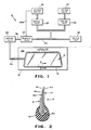
- Figure 1 is a block diagram illustrating the apparatus of the present invention; and
- Figure 2 is a sectional view taken along the line 2-2 of Fig. 1 and illustrating the sealing means coupled around a peripheral edge portion of a stacked arrangement of individual laminae adapted to form a laminated glass assembly.
- The vacuum system 10 of Figure 1 is used in conjunction with an
autoclave unit 12. Theautoclave unit 12 includes a heated and pressurisedchamber 12a for receiving a stacked arrangement of individual plastic andglass laminae 13 adapted to form a laminated glass assembly. The pressure within thechamber 12a, generally within the range of 15.51 - 18.96 bar functions to urge theindividual laminae 13 toward one another, while the heat, generally a temperature within the range of 93 - 149°C., causes the plastic laminae to bond to the adjacent glass laminae. The vacuum system 10 of the present invention is utilised to evacuate the space between theindividual laminae 13 to further urge the individual laminae toward one another. A seal means 16 surrounds the peripheral edge portions of thelaminae 13 and is coupled to the vacuum system 10. - As shown in Fig. 2, the
laminae 13 comprises awindshield assembly 14 and acover sheet 15. Thewindshield assembly 14 includes an outer glass sheet 14a, aninner glass sheet 14b, a plastic interlayer 14c positioned between theglass sheets 14a and 14b, and a secondplastic layer 14d positioned on the surface of theinner glass sheet 14b opposite the plastic interlayer 14c. Thecover sheet 15 is positioned adjacent theplastic layer 14d and is utilised as a press mould to bond theplastic layer 14d to the inner surface of theglass sheet 14b. The surface of thecover sheet 15 adjacent theplastic layer 14d is provided with a suitable wax coating to prevent thelayer 14d from bonding to the cover sheet. The seal means 16 is adapted to sealingly engage the outer surfaces of thesheets 14a and 15 to define an enclosedchamber 16a. - The enclosed
chamber 16a is connected to a conduit section 18a which communicates with avacuum pump 20 through amanual valve 22, aconduit section 18b, asolenoid valve 24, and aconduit section 18c. Avacuum switch 30 is connected to monitor the pressure in theconduit section 18c through amanual valve 26. Theswitch 30 generates a signal on aline 30a to either open or close thesolenoid valve 24, depending on the pressure in theconduit section 18c. When the pressure in theconduit section 18c increases to a predetermined amount, theswitch 30 generates a signal on aline 30a which causes thesolenoid valve 24 to close, thereby disconnecting thevacuum pump 20 from the seal means 16. Avacuum gauge 32 is connected to theconduit section 18c through amanual valve 28 to provide the operator with an indication of the vacuum level in theconduit section 18c. - It has been found desirable to provide a
vacuum switch 30 of the type which will open automatically on a pressure increase above a predetermined set point, but must be manually reset to close on a pressure decrease below the predetermined set point. For example, theswitch 30 can be manually set to close and generate a signal to open the solenoid valve when the pressure in theconduit section 18c falls below atmospheric pressure. Thus, before thevacuum pump 20 is activated, thevacuum switch 30 is open and thesolenoid valve 24 is closed and, when thevacuum pump 20 is activated, thevacuum switch 30 will sense the pressure drop below atmospheric pressure and close to generate a signal on theline 30a, thereby causing thesolenoid valve 24 to open and apply a vacuum within thechamber 16a of the seal means 16. In the event a leak occurs within the sealing means or the associated connections thereto, thevacuum switch 30 will sense the pressure increase above atmospheric pressure and will open to cause thesolenoid valve 24 to close, thus preventing the relatively high pressure within theautoclave unit 12 from entering theconduit section 18c protecting the vacuum pump and the vacuum gauge. In order for theswitch 30 to operate again, the switch must then be manually reset. Themanual valves
Claims (3)
Applications Claiming Priority (2)
| Application Number | Priority Date | Filing Date | Title |
|---|---|---|---|
| US55933783A | 1983-12-08 | 1983-12-08 | |
| US559337 | 1983-12-08 |
Publications (3)
| Publication Number | Publication Date |
|---|---|
| EP0164408A1 EP0164408A1 (en) | 1985-12-18 |
| EP0164408A4 EP0164408A4 (en) | 1987-07-09 |
| EP0164408B1 true EP0164408B1 (en) | 1990-02-28 |
Family
ID=24233216
Family Applications (1)
| Application Number | Title | Priority Date | Filing Date |
|---|---|---|---|
| EP85900369A Expired - Lifetime EP0164408B1 (en) | 1983-12-08 | 1984-12-05 | Vacuum system for use in manufacturing laminated glass |
Country Status (8)
| Country | Link |
|---|---|
| EP (1) | EP0164408B1 (en) |
| JP (1) | JPS61500603A (en) |
| KR (1) | KR910009527B1 (en) |
| AU (1) | AU590715B2 (en) |
| BR (1) | BR8407208A (en) |
| CA (1) | CA1247508A (en) |
| DE (1) | DE3481409D1 (en) |
| WO (1) | WO1985002583A1 (en) |
Cited By (1)
| Publication number | Priority date | Publication date | Assignee | Title |
|---|---|---|---|---|
| CN104354441A (en) * | 2014-11-13 | 2015-02-18 | 梅州市金诺通讯设备有限公司 | Safety pressurizing defoamer for mobile phone |
Families Citing this family (3)
| Publication number | Priority date | Publication date | Assignee | Title |
|---|---|---|---|---|
| NL8520086A (en) * | 1984-04-27 | 1986-03-03 | Libbey Owens Ford Co | METHOD AND APPARATUS FOR APPLICATING AN OPENING PREVENTING PLASTIC COATING ON GLASS |
| DE10340856B4 (en) * | 2003-09-04 | 2009-11-12 | Webasto Ag | Method and apparatus for manufacturing a disc assembly for a vehicle, using the manufactured disc assembly |
| KR200487471Y1 (en) * | 2013-09-20 | 2018-09-20 | 엘지디스플레이 주식회사 | Pressure-sensing stages for lamination systems |
Family Cites Families (5)
| Publication number | Priority date | Publication date | Assignee | Title |
|---|---|---|---|---|
| US2992953A (en) * | 1960-02-23 | 1961-07-18 | Chrysler Corp | Glass laminating de-airing means |
| US3628563A (en) * | 1968-12-10 | 1971-12-21 | Tokyo Shibaura Electric Co | Explosion detecting means for a fluid pipeline |
| US3971668A (en) * | 1974-08-05 | 1976-07-27 | Triplex Safety Glass Company Limited | Formation of laminated glass articles |
| AU2346084A (en) * | 1983-11-29 | 1985-06-13 | Shatterproof Glass Corp. | Method and apparatus for producing laminated glass |
| NL8520086A (en) * | 1984-04-27 | 1986-03-03 | Libbey Owens Ford Co | METHOD AND APPARATUS FOR APPLICATING AN OPENING PREVENTING PLASTIC COATING ON GLASS |
-
1984
- 1984-12-05 BR BR8407208A patent/BR8407208A/en not_active IP Right Cessation
- 1984-12-05 WO PCT/US1984/001985 patent/WO1985002583A1/en not_active Ceased
- 1984-12-05 DE DE8585900369T patent/DE3481409D1/en not_active Expired - Lifetime
- 1984-12-05 EP EP85900369A patent/EP0164408B1/en not_active Expired - Lifetime
- 1984-12-05 KR KR1019850700156A patent/KR910009527B1/en not_active Expired
- 1984-12-05 JP JP59504468A patent/JPS61500603A/en active Pending
- 1984-12-05 AU AU37432/85A patent/AU590715B2/en not_active Ceased
- 1984-12-06 CA CA000469524A patent/CA1247508A/en not_active Expired
Cited By (1)
| Publication number | Priority date | Publication date | Assignee | Title |
|---|---|---|---|---|
| CN104354441A (en) * | 2014-11-13 | 2015-02-18 | 梅州市金诺通讯设备有限公司 | Safety pressurizing defoamer for mobile phone |
Also Published As
| Publication number | Publication date |
|---|---|
| EP0164408A1 (en) | 1985-12-18 |
| CA1247508A (en) | 1988-12-28 |
| AU590715B2 (en) | 1989-11-16 |
| DE3481409D1 (en) | 1990-04-05 |
| WO1985002583A1 (en) | 1985-06-20 |
| KR850700124A (en) | 1985-10-25 |
| BR8407208A (en) | 1985-11-05 |
| KR910009527B1 (en) | 1991-11-21 |
| EP0164408A4 (en) | 1987-07-09 |
| JPS61500603A (en) | 1986-04-03 |
| AU3743285A (en) | 1985-06-26 |
Similar Documents
| Publication | Publication Date | Title |
|---|---|---|
| US4944822A (en) | Method for press-bonding laminated assembly | |
| EP0247402B1 (en) | Vibration resistant explosion control vent | |
| US6354142B1 (en) | Process for testing the tightness of packages | |
| EP0149130B1 (en) | A method for sealing an emptying opening and an arrangement for the realization of the method | |
| US4425406A (en) | Method and apparatus for producing laminated glass | |
| EP0194555B1 (en) | Process for producing a laminate | |
| US4624731A (en) | Vacuum ring for producing laminated glass | |
| GB2289649A (en) | Laminated glass safety pane | |
| WO2014179086A2 (en) | Vacuum bag molding assembly and methods | |
| EP0130441A2 (en) | Pressure measuring system | |
| US4732639A (en) | Vacuum bagging apparatus | |
| AU590715B2 (en) | Vacuum system for use in manufacturing laminated glass | |
| US4822651A (en) | Vacuum diaphragm device | |
| US4040888A (en) | Apparatus for prepressing transparent laminated assemblies | |
| US4211251A (en) | Automatic purging system | |
| CA2105728A1 (en) | Semiconductor Type Differential Pressure Measurement Apparatus and Method for Manufacturing the Same | |
| US4999165A (en) | Pressure vessel with improved gasket valve | |
| US6715985B2 (en) | Gas conditioning system | |
| GB2270962A (en) | A flexible connecting duct | |
| US4169225A (en) | Electric heating apparatus with automatic purging system | |
| NL8520086A (en) | METHOD AND APPARATUS FOR APPLICATING AN OPENING PREVENTING PLASTIC COATING ON GLASS | |
| JPH1089507A (en) | Pressure relief device used in heater by saturated steam of heating medium | |
| WO1991014564A1 (en) | An evacuation chamber | |
| US2464540A (en) | Method and apparatus for producing laminated safety glass | |
| EP0605994A1 (en) | Process for encapsulating photovoltaic cells in laminated glazings |
Legal Events
| Date | Code | Title | Description |
|---|---|---|---|
| PUAI | Public reference made under article 153(3) epc to a published international application that has entered the european phase |
Free format text: ORIGINAL CODE: 0009012 |
|
| 17P | Request for examination filed |
Effective date: 19850813 |
|
| AK | Designated contracting states |
Designated state(s): BE DE FR GB LU NL SE |
|
| RAP1 | Party data changed (applicant data changed or rights of an application transferred) |
Owner name: LOF GLASS INC Owner name: LIBBEY-OWENS-FORD COMPANY |
|
| A4 | Supplementary search report drawn up and despatched |
Effective date: 19870709 |
|
| RAP1 | Party data changed (applicant data changed or rights of an application transferred) |
Owner name: LOF GLASS INC |
|
| 17Q | First examination report despatched |
Effective date: 19881222 |
|
| GRAA | (expected) grant |
Free format text: ORIGINAL CODE: 0009210 |
|
| AK | Designated contracting states |
Kind code of ref document: B1 Designated state(s): BE DE FR GB LU NL SE |
|
| REF | Corresponds to: |
Ref document number: 3481409 Country of ref document: DE Date of ref document: 19900405 |
|
| ET | Fr: translation filed | ||
| PGFP | Annual fee paid to national office [announced via postgrant information from national office to epo] |
Ref country code: LU Payment date: 19901016 Year of fee payment: 7 |
|
| PGFP | Annual fee paid to national office [announced via postgrant information from national office to epo] |
Ref country code: GB Payment date: 19901119 Year of fee payment: 7 |
|
| PGFP | Annual fee paid to national office [announced via postgrant information from national office to epo] |
Ref country code: SE Payment date: 19901205 Year of fee payment: 7 |
|
| PGFP | Annual fee paid to national office [announced via postgrant information from national office to epo] |
Ref country code: FR Payment date: 19901218 Year of fee payment: 7 |
|
| PLBE | No opposition filed within time limit |
Free format text: ORIGINAL CODE: 0009261 |
|
| STAA | Information on the status of an ep patent application or granted ep patent |
Free format text: STATUS: NO OPPOSITION FILED WITHIN TIME LIMIT |
|
| PGFP | Annual fee paid to national office [announced via postgrant information from national office to epo] |
Ref country code: DE Payment date: 19901221 Year of fee payment: 7 |
|
| PG25 | Lapsed in a contracting state [announced via postgrant information from national office to epo] |
Ref country code: LU Free format text: LAPSE BECAUSE OF NON-PAYMENT OF DUE FEES Effective date: 19901231 |
|
| PGFP | Annual fee paid to national office [announced via postgrant information from national office to epo] |
Ref country code: NL Payment date: 19901231 Year of fee payment: 7 |
|
| 26N | No opposition filed | ||
| PGFP | Annual fee paid to national office [announced via postgrant information from national office to epo] |
Ref country code: BE Payment date: 19910227 Year of fee payment: 7 |
|
| EPTA | Lu: last paid annual fee | ||
| PG25 | Lapsed in a contracting state [announced via postgrant information from national office to epo] |
Ref country code: GB Effective date: 19911205 |
|
| PG25 | Lapsed in a contracting state [announced via postgrant information from national office to epo] |
Ref country code: SE Effective date: 19911206 |
|
| PG25 | Lapsed in a contracting state [announced via postgrant information from national office to epo] |
Ref country code: BE Effective date: 19911231 |
|
| BERE | Be: lapsed |
Owner name: LOF GLASS INC. Effective date: 19911231 |
|
| PG25 | Lapsed in a contracting state [announced via postgrant information from national office to epo] |
Ref country code: NL Effective date: 19920701 |
|
| GBPC | Gb: european patent ceased through non-payment of renewal fee | ||
| NLV4 | Nl: lapsed or anulled due to non-payment of the annual fee | ||
| PG25 | Lapsed in a contracting state [announced via postgrant information from national office to epo] |
Ref country code: FR Effective date: 19920831 |
|
| PG25 | Lapsed in a contracting state [announced via postgrant information from national office to epo] |
Ref country code: DE Effective date: 19920901 |
|
| REG | Reference to a national code |
Ref country code: FR Ref legal event code: ST |
|
| EUG | Se: european patent has lapsed |
Ref document number: 85900369.1 Effective date: 19920704 |