EP0163613B1 - Optical interferometer with dispersion deviator - Google Patents
Optical interferometer with dispersion deviator Download PDFInfo
- Publication number
- EP0163613B1 EP0163613B1 EP85830097A EP85830097A EP0163613B1 EP 0163613 B1 EP0163613 B1 EP 0163613B1 EP 85830097 A EP85830097 A EP 85830097A EP 85830097 A EP85830097 A EP 85830097A EP 0163613 B1 EP0163613 B1 EP 0163613B1
- Authority
- EP
- European Patent Office
- Prior art keywords
- grating
- interferometer
- reflected
- mirror
- diffracted
- Prior art date
- Legal status (The legal status is an assumption and is not a legal conclusion. Google has not performed a legal analysis and makes no representation as to the accuracy of the status listed.)
- Expired - Lifetime
Links
- 230000003287 optical effect Effects 0.000 title description 16
- 239000006185 dispersion Substances 0.000 title 1
- 239000000470 constituent Substances 0.000 claims description 3
- 238000010586 diagram Methods 0.000 description 13
- 230000003595 spectral effect Effects 0.000 description 12
- 238000002310 reflectometry Methods 0.000 description 2
- 238000004458 analytical method Methods 0.000 description 1
- 230000005540 biological transmission Effects 0.000 description 1
- 239000011248 coating agent Substances 0.000 description 1
- 238000000576 coating method Methods 0.000 description 1
- 230000002596 correlated effect Effects 0.000 description 1
- 230000000875 corresponding effect Effects 0.000 description 1
- 239000000463 material Substances 0.000 description 1
- 239000000203 mixture Substances 0.000 description 1
- 239000010453 quartz Substances 0.000 description 1
- 230000001105 regulatory effect Effects 0.000 description 1
- VYPSYNLAJGMNEJ-UHFFFAOYSA-N silicon dioxide Inorganic materials O=[Si]=O VYPSYNLAJGMNEJ-UHFFFAOYSA-N 0.000 description 1
- 238000004611 spectroscopical analysis Methods 0.000 description 1
- 238000001228 spectrum Methods 0.000 description 1
- 239000012780 transparent material Substances 0.000 description 1
Images




Classifications
-
- G—PHYSICS
- G01—MEASURING; TESTING
- G01J—MEASUREMENT OF INTENSITY, VELOCITY, SPECTRAL CONTENT, POLARISATION, PHASE OR PULSE CHARACTERISTICS OF INFRARED, VISIBLE OR ULTRAVIOLET LIGHT; COLORIMETRY; RADIATION PYROMETRY
- G01J3/00—Spectrometry; Spectrophotometry; Monochromators; Measuring colours
- G01J3/12—Generating the spectrum; Monochromators
- G01J3/26—Generating the spectrum; Monochromators using multiple reflection, e.g. Fabry-Perot interferometer, variable interference filters
-
- H—ELECTRICITY
- H01—ELECTRIC ELEMENTS
- H01S—DEVICES USING THE PROCESS OF LIGHT AMPLIFICATION BY STIMULATED EMISSION OF RADIATION [LASER] TO AMPLIFY OR GENERATE LIGHT; DEVICES USING STIMULATED EMISSION OF ELECTROMAGNETIC RADIATION IN WAVE RANGES OTHER THAN OPTICAL
- H01S3/00—Lasers, i.e. devices using stimulated emission of electromagnetic radiation in the infrared, visible or ultraviolet wave range
- H01S3/10—Controlling the intensity, frequency, phase, polarisation or direction of the emitted radiation, e.g. switching, gating, modulating or demodulating
- H01S3/105—Controlling the intensity, frequency, phase, polarisation or direction of the emitted radiation, e.g. switching, gating, modulating or demodulating by controlling the mutual position or the reflecting properties of the reflectors of the cavity, e.g. by controlling the cavity length
- H01S3/1055—Controlling the intensity, frequency, phase, polarisation or direction of the emitted radiation, e.g. switching, gating, modulating or demodulating by controlling the mutual position or the reflecting properties of the reflectors of the cavity, e.g. by controlling the cavity length one of the reflectors being constituted by a diffraction grating
-
- H—ELECTRICITY
- H01—ELECTRIC ELEMENTS
- H01S—DEVICES USING THE PROCESS OF LIGHT AMPLIFICATION BY STIMULATED EMISSION OF RADIATION [LASER] TO AMPLIFY OR GENERATE LIGHT; DEVICES USING STIMULATED EMISSION OF ELECTROMAGNETIC RADIATION IN WAVE RANGES OTHER THAN OPTICAL
- H01S3/00—Lasers, i.e. devices using stimulated emission of electromagnetic radiation in the infrared, visible or ultraviolet wave range
- H01S3/10—Controlling the intensity, frequency, phase, polarisation or direction of the emitted radiation, e.g. switching, gating, modulating or demodulating
- H01S3/106—Controlling the intensity, frequency, phase, polarisation or direction of the emitted radiation, e.g. switching, gating, modulating or demodulating by controlling devices placed within the cavity
- H01S3/1062—Controlling the intensity, frequency, phase, polarisation or direction of the emitted radiation, e.g. switching, gating, modulating or demodulating by controlling devices placed within the cavity using a controlled passive interferometer, e.g. a Fabry-Perot etalon
-
- H—ELECTRICITY
- H01—ELECTRIC ELEMENTS
- H01S—DEVICES USING THE PROCESS OF LIGHT AMPLIFICATION BY STIMULATED EMISSION OF RADIATION [LASER] TO AMPLIFY OR GENERATE LIGHT; DEVICES USING STIMULATED EMISSION OF ELECTROMAGNETIC RADIATION IN WAVE RANGES OTHER THAN OPTICAL
- H01S3/00—Lasers, i.e. devices using stimulated emission of electromagnetic radiation in the infrared, visible or ultraviolet wave range
- H01S3/14—Lasers, i.e. devices using stimulated emission of electromagnetic radiation in the infrared, visible or ultraviolet wave range characterised by the material used as the active medium
- H01S3/22—Gases
- H01S3/223—Gases the active gas being polyatomic, i.e. containing two or more atoms
- H01S3/2232—Carbon dioxide (CO2) or monoxide [CO]
-
- H—ELECTRICITY
- H01—ELECTRIC ELEMENTS
- H01S—DEVICES USING THE PROCESS OF LIGHT AMPLIFICATION BY STIMULATED EMISSION OF RADIATION [LASER] TO AMPLIFY OR GENERATE LIGHT; DEVICES USING STIMULATED EMISSION OF ELECTROMAGNETIC RADIATION IN WAVE RANGES OTHER THAN OPTICAL
- H01S3/00—Lasers, i.e. devices using stimulated emission of electromagnetic radiation in the infrared, visible or ultraviolet wave range
- H01S3/14—Lasers, i.e. devices using stimulated emission of electromagnetic radiation in the infrared, visible or ultraviolet wave range characterised by the material used as the active medium
- H01S3/22—Gases
- H01S3/223—Gases the active gas being polyatomic, i.e. containing two or more atoms
- H01S3/225—Gases the active gas being polyatomic, i.e. containing two or more atoms comprising an excimer or exciplex
- H01S3/2255—XeF, i.e. xenon fluoride is comprised for lasing around 351 nm
Definitions
- the present invention relates to interferometers wherein the splitting of the incident beam into the beams which are to be made to interfere with one another is achieved by means of deviators which consist of diffraction gratings.
- Interferometers comprising one or more reflecting surfaces according to the Fabry-Perot, Fox-Smith, Michelson, Petrun'kin (B, C, D in Fig. 1) types are well known.
- the operation of the B, C, D types may be thus summarized: an electromagnetic wave shown by heavy type arrows in Fig. 1 and represented by a spectral function f(k) incides on optical element S of Fig. 1.
- a portion of this wave, represented by a spectral function f r (k) is reflected while another portion f t (k) is transmitted.
- the reflected and transmitted portions are indicated by two light type arrows in Fig. 1.
- the spectral properties of the above spectrometers are determined by the optical characteristics and by the reciprocal distances of the reflecting surfaces.
- the element whereby the optical elements of the system are coupled to one another and whereby the incident beam is admitted to the interferometer and the outcoming beams are drawn therefrom, will be called “deviator” hereinafter.
- the optical deviator indicated by S in Fig. 1 usually comprises a plate of suitable transparent material of which one or both the faces are coated by reflecting and or reflection-preventing material.
- Such deviator due to its coating, can have the drawback of a low damage threshold at high light intensities and of a spectral field restricted by the layers deposited on its surfaces.
- the interferometer comprising a diffraction grating (G), acting as the deviator element, and reflection means as set out in the claims.
- G diffraction grating
- interferometers of the B, C, D type wherein gratings of suitable characteristics are used as elements S is a way, of evidenced by experimental results for producing high power laser cavities operating in a single mode.
- the interferometers herein described are employed as output couplers in lieu of the semi- transparent mirror usually employed.
- An incident beam on grating G produces a series of emergent beams Ri characterized by the following generic spectral function.
- F,(k) is the reflection spectral function of the grating related to the j th order and f(k) that related to the incident beam.
- the diffracted beam characterized by spectral fucntion f o (k) still exists.
- the beam which in Fig. 1 is indicated by R represents the beam related to the generical diffraction order i with O ⁇ i ⁇ n wherein n is the maximum diffraction order existing in the chosen optical configuration.
- a light beam inciding on the grating surface at an angle ⁇ 1 splits in a "reflected" part and in one or more diffracted parts.
- the diffracted part of the generic i order is part of the interferometer transmitted beam.
- the diffracted part of i order is orthogonally reflected by mirror M 2 and returned to incide on the grating wherein it splits again in more parts.
- the reflected part is part of the interferometer transmitted beam.
- the diffracted part of i order is returned to reflect on M 1 wherefrom it begins its above described optical path.
- a light beam inciding on the grating surface splits into a "reflected" part and one or more diffracted parts.
- the "reflected" part following orthogonal reflection by mirror M1 incides again on the grating.
- Said "reflected" part is part of the interferometer reflected beam while the diffracted part is part of the interferometer transmitted beam.
- That part initially diffracted by the grating on i order, following orthogonal reflection on mirror M 2 incides again on the grating and splits again in several parts.
- the diffracted part of i order proceeds to form the interferometer reflected beam.
- a light beam inciding on the grating surface splits into a "reflected" part and into one or more diffracted parts.
- the "reflected” part proceeds to form the interferometer transmitted beam.
- the diffracted part of i order following orthogonal reflection on mirror M 2 incides again on the grating where it splits into two or more aprts.
- the diffracted part of order i proceeds to form the interferometer reflected beam.
- the "reflected" part, following orthogonal reflection on mirror M 1 incides again on the grating.
- the diffracted part proceeds to form the interferometer transmitted beam while the reflected part reflects on mirror M 2 wherefrom it begins the above described optical path.
- This interferometer which derives from type A of Fig. 1 comprises a grating G and a mirror M 1 parallel facing each other. Its operation is as follows: a beam incides on grating G where it splits into two or more parts: a reflected one and a diffracted one. The reflected part forms the interferometer transmitted beam.
- the diffracted part emerging leftwards in Fig. 8 proceeds to form the interferometer reflected beam.
- the "reflected" part begins again the above optical path.
- Mirror M 1 may be replaced by a grating G 1 disposed in the same position as M 1 (Fig. 8a) or at a Littrow angle (Fig. 8b).
- This interferometer comprises a grating G facing another grating G i .
- Grating G 1 provided that its constant is the same as of grating G, will be parallel faced thereto while when its constant is different it will be faced to G so as to be at Littrow angle with respect to the incident beam (Fig. 9a).
- Grating G 1 may also be replaced by a mirror M 1 orthogonally positioned with respect to the incident beam (Fig. 9).
- the "reflected" part proceeds to form the transmitted part of the interferometer.
- the part diffracted at Littrow angle, after inciding at Littrow angle on grating G 1 turns back to incide still at Littrow angle on grating G.
- the leftwards (in Fig. 9b) diffracted part proceeds to form the interferometer reflected beam.
- the part diffracted at Littrow angle turns back to follow again the described optical path.
- It comprises a partially reflecting mirror M, orthogonal to the beam emerging from a grating G.
- the operation is as follows: a beam inciding on grating G at Littrow angle splits into two or more parts.
- the part diffracted leftwards (in Fig. 10) at Littrow angle to the normal forms part of the interferometer reflected beam.
- the rightwards (in Fig. 10) diffracted part at Littrow angle incides orthogonally on mirror M, where it splits in two parts: a transmitted one and a reflected one.
- the transmitted part forms part of the interferometer transmitted beam, the reflected part incides again on grating G where it splits again into more parts.
- a beam orthogonally incident on grating G splits in three or more parts.
- the orthogonally "reflected" part proceeds to form the interferometer reflected beam, the diffracted part of order i directed rightwards (in Fig. 11) orthogonally incides the mirror M, and then returns on grating G where it splits again into more parts.
- the reflected part proceeds to form the transmitted beam of the interferometer and the diffracted part of order i is constituent part of the interferometer reflected beam.
- Mirror M 1 may be replaced by a grating G 1 operating at Littrow angle (Fig. 11a).
- the operation is as follows: a beam orthogonally inciding on grating G, at an angle 0, different from ⁇ L splits into three of more parts.
- the orthogonally reflected part is part of the interferometer reflected beam.
- the part of order i diffracted leftwards (in Fig. 12) orthogonally reflects on mirror M 2 and then it incides again on the grating where it splits in more parts.
- the diffracted part of order i makes part of the interferometer reflected beam.
- diffracted one orthogonally reflects on mirror M, and incides again on grating G where it splits into more parts.
- the diffracted part of order i is part of the interferometer reflected beam while the reflected part begins again the above optical path.
- the optical characteristics of the grating interferometers of Fig. 8 and 9 are similar to those of the configuration of Fig. 6.
- the characteristics of the grating interferometer of Fig. 11 are similar to the interferometer of Fig. 5.
- the characteristics of grating interferometers of Figs. 10 and 12 are similar to the interferometer of Fig. 1A.
- the mirrors may both or only one be replaced by diffraction gratings of suitable characteristics which operate by reflection (Littrow configuration of Fig. 2).
- a grating interferometer as shown in Fig. 8 has been utilized as output coupler in a XeF laser operating in the uv band at 350 nm for producing a laser emission tunable with a very narrow spectrum width.
- the apparatus comprised: a laser cavity consisting of a tube 20 wherein a mixture of Xe and F 2 was excited by a transverse discharge and which was closed at each end by a quartz window; a dielectric flat mirror 23 with 99% reflectivity; an iris 24 for regulating the quality of the laser beam transverse profile; an interferometer 26 of the type shown in Fig.
- interferometer 8 which comprised a high reflectivity dielectric mirror 28 and a diffraction holographic grating 30 with 2400 lines for mm which interferometer constituted the output mirror of the laser cavity.
- interferometer 26 whose spectral periodicity was 7.5 GHz with a fineness of 13 a single and transverse mode of the laser operation has been obtained with a line with lower than 50 MHz.
- micrometric rotation of grating interferometer 26 the laser frequency emitted by the same on a spectral band of 1.5 nm could be tuned.
Landscapes
- Physics & Mathematics (AREA)
- Electromagnetism (AREA)
- Spectroscopy & Molecular Physics (AREA)
- Engineering & Computer Science (AREA)
- Plasma & Fusion (AREA)
- Optics & Photonics (AREA)
- General Physics & Mathematics (AREA)
- Instruments For Measurement Of Length By Optical Means (AREA)
Description
- The present invention relates to interferometers wherein the splitting of the incident beam into the beams which are to be made to interfere with one another is achieved by means of deviators which consist of diffraction gratings.
- Interferometers comprising one or more reflecting surfaces according to the Fabry-Perot, Fox-Smith, Michelson, Petrun'kin (B, C, D in Fig. 1) types are well known. The operation of the B, C, D types may be thus summarized: an electromagnetic wave shown by heavy type arrows in Fig. 1 and represented by a spectral function f(k) incides on optical element S of Fig. 1. A portion of this wave, represented by a spectral function fr(k), is reflected while another portion ft(k) is transmitted. The reflected and transmitted portions are indicated by two light type arrows in Fig. 1. The above functions fr(k) and ft(k) are correlated to function f(k) thorugh the following equations:


- The spectral properties of the above spectrometers are determined by the optical characteristics and by the reciprocal distances of the reflecting surfaces. The element whereby the optical elements of the system are coupled to one another and whereby the incident beam is admitted to the interferometer and the outcoming beams are drawn therefrom, will be called "deviator" hereinafter. In interferometers B, C, D the optical deviator indicated by S in Fig. 1, usually comprises a plate of suitable transparent material of which one or both the faces are coated by reflecting and or reflection-preventing material.
- Such deviator, due to its coating, can have the drawback of a low damage threshold at high light intensities and of a spectral field restricted by the layers deposited on its surfaces.
- An analysis of the limiting possibilities of wide- field spectrometers with selective interference comprising a two-beam interferometer in which one or two mirrors are replaced by diffraction gratings is disclosed by L. V. Egorova and B. A. Kiselev in Optics and Spectroscopy Vol. 45 No. 1 (1978.07).
- These advantages are achieved, according to the present invention, by the interferometer comprising a diffraction grating (G), acting as the deviator element, and reflection means as set out in the claims.
- By replacing plate S with a grating, due to the dispersive properties of the latter, the limitation can be overcome which consists of the periodical character of the spectral response of the above mentioned interferometers.
- The development of interferometers of the B, C, D type wherein gratings of suitable characteristics are used as elements S, is a way, of evidenced by experimental results for producing high power laser cavities operating in a single mode. In such cavities the interferometers herein described are employed as output couplers in lieu of the semi- transparent mirror usually employed.
- This invention will be more readily understood from the following description and attached drawings which illustrate by way of examples two main embodiments and several variants thereof. In the drawings:
- Fig. 1 shows in the order, in a very simplified form, the optical diagrams (A, B, C, D) of the known Fabry-Perot, Fox-Smith, Michelson and Petrun'kin interferometers.
- Fig. 2 is a diagram which shows how one or both V of the mirrors M, and M2 of the interferometers according to optical configuration of Fig. 1 can be replaced by diffraction gratings functioning as reflectors (Littrow configuration).
- Fig. 3 is a diagram which shows the operation of a diffraction grating and how it can be used as deviator element in an interferometer;
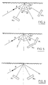
- Figs. 4, 5, 6 are the optical diagrams of the B, C, D (that is Fox-Smith, Michelson and Petrun'kin) interferometers wherein the deviator element is replaced by a diffraction grating.
- Fig. 7 shows how the grating interferometer of Fig. 8 can be used as output coupler in an XeF laser;
- Fig. 8 shows a grating interferometer wherein a grating and a mirror are included which face each other parallel to one another;
- Fig. 8a shows a grating interferometer whose diagram is the same as in Fig. 8 and wherein the mirror is replaced by a grating which faces grating G of Fig. 8 parallel thereto;
- Fig. 8b shows an interferometer whose diagram is the same as in Fig. 8 and wherein the mirror is replaced by a grating; the two gratings being at Littrow angle with respect to one another;
- Fig. 9 shows a grating interferometer wherein a grating and a mirror are included which are disposed at Littrow angle to one another;
- Fig. 9a shows the diagram of a grating interferometer comprising a grating which faces another grating at an angle such that it results in Littrow with respect to the incident beam;
- Fig. 9b shows the diagram of an interferometer similar to Fig. 9 wherein the mirror is replaced by a grating at Littrow angle with the other grating;
- Fig. 10 shows the diagram of a grating interferometer wherein a grating and a partially reflecting mirror are included; the mirror face being perpendicular to the beam from the grating;
- Fig. 10a shows the diagram of a grating interferometer similar to that of Fig. 10 wherein the mirror is replaced by a second grating facing the first one at Littrow angle;
- Fig. 11 shows the diagram of a grating interferometer wherein a grating and a mirror are included and wherein the entering beam is directed perpendicularly to the grating surface;
- Fig. 11 a shows the diagram of a grating interferometer similar to Fig. 11 wherein the mirror is replaced by a grating which operates at Littrow angle;
- Fig. 12 shows the diagram of a grating interferometer wherein a grating and two mirrors are included one of which is partially reflecting;
- Fig. 12a shows a grating interferometer similar to Fig. 12 wherein the partially reflecting mirror is replaced by a grating which operates at Littrow angle.
- With reference to Fig. 3, the operating principle of a grating when employed as deviator in an interferometer is as follows:
- An incident beam on grating G produces a series of emergent beams Ri characterized by the following generic spectral function.

- Such beam indicated by R. in Fig. 3 has the property that θ1=θD o; i.e. the diffraction angle does not depend on 6, nor on k and such diffractive order can be understood as a reflection of the Fresnel type. The beam which in Fig. 1 is indicated by R, represents the beam related to the generical diffraction order i with O<i<n wherein n is the maximum diffraction order existing in the chosen optical configuration. The grating interferometers corresponding to the conventional types B, C, D of Fig. 1 can be described in the same way as for the above prism interferometers provided that the beams transmitted and reflected by face C of the prism be replaced respectively by the "reflected" beam Ro and by the refracted beam R, of the grating. It is to be borne in mind that in the case of a grating, by the term "reflected" the specular component is meant of the beams reflected by the grating. In this case the spectral characteristics of interferometers B, C, D of Fig. 1 are determined by the angle and polarisation of the incident beam, by the grating characteristics, by the chosen order R, and by the interferometer configuration.
- The above mentioned variants of grating interferometers according to the invention will be now described.
- A light beam inciding on the grating surface at an angle θ1 splits in a "reflected" part and in one or more diffracted parts. The diffracted part of the generic i order is part of the interferometer transmitted beam. The diffracted part of i order is orthogonally reflected by mirror M2 and returned to incide on the grating wherein it splits again in more parts. The reflected part is part of the interferometer transmitted beam. The diffracted part of i order is returned to reflect on M1 wherefrom it begins its above described optical path.
- A light beam inciding on the grating surface splits into a "reflected" part and one or more diffracted parts. The "reflected" part, following orthogonal reflection by mirror M1 incides again on the grating. Said "reflected" part is part of the interferometer reflected beam while the diffracted part is part of the interferometer transmitted beam. That part initially diffracted by the grating on i order, following orthogonal reflection on mirror M2 incides again on the grating and splits again in several parts. The diffracted part of i order proceeds to form the interferometer reflected beam.
- A light beam inciding on the grating surface splits into a "reflected" part and into one or more diffracted parts. The "reflected" part proceeds to form the interferometer transmitted beam. The diffracted part of i order, following orthogonal reflection on mirror M2 incides again on the grating where it splits into two or more aprts. The diffracted part of order i proceeds to form the interferometer reflected beam. The "reflected" part, following orthogonal reflection on mirror M1 incides again on the grating. The diffracted part proceeds to form the interferometer transmitted beam while the reflected part reflects on mirror M2 wherefrom it begins the above described optical path.
- From the above discussion it clearly appears that the diffracted orders R1 and the reflected one Ro, when suitably combined, can give way to interferometric configuration different from those of Figs. 4, 5, 6.
- For instance:
- Configuration d' (Fig. 8)
- This interferometer which derives from type A of Fig. 1 comprises a grating G and a mirror M1 parallel facing each other. Its operation is as follows: a beam incides on grating G where it splits into two or more parts: a reflected one and a diffracted one. The reflected part forms the interferometer transmitted beam. The diffracted part R, of order i emerges from the grating an an angle θ,=θD o and proceeds to reflect orthogonally on mirror M1 and to incide again orthogonally on the grating. The diffracted part emerging leftwards in Fig. 8 proceeds to form the interferometer reflected beam. The "reflected" part begins again the above optical path. Mirror M1 may be replaced by a grating G1 disposed in the same position as M1 (Fig. 8a) or at a Littrow angle (Fig. 8b).
- This interferometer comprises a grating G facing another grating Gi. Grating G1, provided that its constant is the same as of grating G, will be parallel faced thereto while when its constant is different it will be faced to G so as to be at Littrow angle with respect to the incident beam (Fig. 9a).
- Grating G1 may also be replaced by a mirror M1 orthogonally positioned with respect to the incident beam (Fig. 9).
- Operation: A beam incides on grating G at an angle different from Littrow angle θL giving rise to a "reflected" beam and to a plurality of diffracted beams one of which at Littrow angle θL. The "reflected" part proceeds to form the transmitted part of the interferometer. The part diffracted at Littrow angle, after inciding at Littrow angle on grating G1 turns back to incide still at Littrow angle on grating G. The leftwards (in Fig. 9b) diffracted part proceeds to form the interferometer reflected beam. The part diffracted at Littrow angle turns back to follow again the described optical path.
- It comprises a partially reflecting mirror M, orthogonal to the beam emerging from a grating G. The operation is as follows: a beam inciding on grating G at Littrow angle splits into two or more parts. The part diffracted leftwards (in Fig. 10) at Littrow angle to the normal forms part of the interferometer reflected beam. The rightwards (in Fig. 10) diffracted part at Littrow angle incides orthogonally on mirror M, where it splits in two parts: a transmitted one and a reflected one. The transmitted part forms part of the interferometer transmitted beam, the reflected part incides again on grating G where it splits again into more parts. The part diffracted leftwards (in Fig. 10) at Littrow angle proceeds to form the interferometer reflected beam. The part diffracted rightwards, also at Littrow angle returns towards mirror M, and begins again the above described optical path. Mirror M, may be replaced by a second grating G1 disposed at Littrow angle (Fig. 10a).
- It comprises a diffraction grating G and a mirror Mi, the direction of the entering beam being orthogonal to the grating surface. The operation is as follows: a beam orthogonally incident on grating G splits in three or more parts. The orthogonally "reflected" part proceeds to form the interferometer reflected beam, the diffracted part of order i directed rightwards (in Fig. 11) orthogonally incides the mirror M, and then returns on grating G where it splits again into more parts. The reflected part proceeds to form the transmitted beam of the interferometer and the diffracted part of order i is constituent part of the interferometer reflected beam.
- Mirror M1 may be replaced by a grating G1 operating at Littrow angle (Fig. 11a).
- It comprises two mirrors M1 and M2, of which one is partially reflecting and a grating G. The operation is as follows: a beam orthogonally inciding on grating G, at an angle 0, different from θL splits into three of more parts. The orthogonally reflected part is part of the interferometer reflected beam. The part of order i diffracted leftwards (in Fig. 12) orthogonally reflects on mirror M2 and then it incides again on the grating where it splits in more parts. The diffracted part of order i makes part of the interferometer reflected beam. The reflected part together with the initially rightwards (in Fig. 12) diffracted one orthogonally reflects on mirror M, and incides again on grating G where it splits into more parts. The diffracted part of order i is part of the interferometer reflected beam while the reflected part begins again the above optical path.
- In the above configuration (Fig. 12) both or only one of the mirrors may be replaced by gratings operating at Littrow angle. Thus, for instance the configuration of Fig. 12a may be obtained.
- The optical characteristics of the grating interferometers of Fig. 8 and 9 are similar to those of the configuration of Fig. 6. The characteristics of the grating interferometer of Fig. 11 are similar to the interferometer of Fig. 5. The characteristics of grating interferometers of Figs. 10 and 12 are similar to the interferometer of Fig. 1A.
- In all the above described grating interferometers the mirrors may both or only one be replaced by diffraction gratings of suitable characteristics which operate by reflection (Littrow configuration of Fig. 2).
- A grating interferometer as shown in Fig. 8 has been utilized as output coupler in a XeF laser operating in the uv band at 350 nm for producing a laser emission tunable with a very narrow spectrum width. The apparatus comprised: a laser cavity consisting of a
tube 20 wherein a mixture of Xe and F2 was excited by a transverse discharge and which was closed at each end by a quartz window; a dielectricflat mirror 23 with 99% reflectivity; aniris 24 for regulating the quality of the laser beam transverse profile; aninterferometer 26 of the type shown in Fig. 8 which comprised a highreflectivity dielectric mirror 28 and a diffractionholographic grating 30 with 2400 lines for mm which interferometer constituted the output mirror of the laser cavity. Byinterferometer 26 whose spectral periodicity was 7.5 GHz with a fineness of 13 a single and transverse mode of the laser operation has been obtained with a line with lower than 50 MHz. By micrometric rotation of gratinginterferometer 26, the laser frequency emitted by the same on a spectral band of 1.5 nm could be tuned.
Claims (14)
Applications Claiming Priority (2)
| Application Number | Priority Date | Filing Date | Title |
|---|---|---|---|
| IT4811284 | 1984-04-30 | ||
| IT8448112A IT1213280B (en) | 1984-04-30 | 1984-04-30 | OPTICAL INTERFEROMETER WITH DISPERSIVE DIVERTER ELEMENT |
Publications (3)
| Publication Number | Publication Date |
|---|---|
| EP0163613A2 EP0163613A2 (en) | 1985-12-04 |
| EP0163613A3 EP0163613A3 (en) | 1986-04-23 |
| EP0163613B1 true EP0163613B1 (en) | 1990-03-21 |
Family
ID=11264592
Family Applications (1)
| Application Number | Title | Priority Date | Filing Date |
|---|---|---|---|
| EP85830097A Expired - Lifetime EP0163613B1 (en) | 1984-04-30 | 1985-04-24 | Optical interferometer with dispersion deviator |
Country Status (4)
| Country | Link |
|---|---|
| US (1) | US4682893A (en) |
| EP (1) | EP0163613B1 (en) |
| DE (1) | DE3576725D1 (en) |
| IT (1) | IT1213280B (en) |
Families Citing this family (8)
| Publication number | Priority date | Publication date | Assignee | Title |
|---|---|---|---|---|
| ES2077520B1 (en) * | 1993-11-08 | 1998-02-16 | Fagor S Coop Ltda | INTERFEROMETER WITH DIFFERATION NETWORK FOR MEASURING LENGTHS. |
| DE10025694C2 (en) * | 2000-05-24 | 2003-06-05 | Zeiss Carl | Use of a diffraction grating |
| US7440113B2 (en) * | 2005-12-23 | 2008-10-21 | Agilent Technologies, Inc. | Littrow interferometer |
| WO2007134642A1 (en) | 2006-05-24 | 2007-11-29 | Universität Hannover | Laser device comprising a diffraction grating and coupled laser resonators |
| EP3006902B1 (en) | 2010-03-30 | 2018-04-11 | Zygo Corporation | Lithography method and lithography system |
| DE102011085614B4 (en) | 2011-11-02 | 2013-06-13 | HighFinesse GmbH | Laser system with resonator |
| DE102011088224A1 (en) | 2011-12-12 | 2013-06-13 | HighFinesse GmbH | Laser system e.g. titanium, sapphire laser system, for use in e.g. high-resolution spectroscopy application, has wavelength-selective element i.e. narrow-band interference filter, arranged in beam path of decoupled portion in chamber |
| CN115876090B (en) * | 2022-09-29 | 2026-03-31 | 哈尔滨工业大学 | Reflective Fabry-Perot Grating Interferometric Displacement Measurement Method and System |
Citations (2)
| Publication number | Priority date | Publication date | Assignee | Title |
|---|---|---|---|---|
| US3443871A (en) * | 1965-12-07 | 1969-05-13 | Optomechanisms Inc | Single optical block interferometer means |
| US3611181A (en) * | 1968-10-10 | 1971-10-05 | United Aircraft Corp | Laser diffraction grating coupling mirror |
Family Cites Families (6)
| Publication number | Priority date | Publication date | Assignee | Title |
|---|---|---|---|---|
| US3090279A (en) * | 1960-05-13 | 1963-05-21 | Bausch & Lomb | Interferometer using a diffraction grating |
| US3332314A (en) * | 1963-04-08 | 1967-07-25 | Kollsman Instr Corp | Optical interferometric navigational instrument |
| FR2168948B1 (en) * | 1972-01-27 | 1976-07-09 | Anvar | |
| JPS561608B2 (en) * | 1974-04-27 | 1981-01-14 | ||
| US4502144A (en) * | 1982-06-10 | 1985-02-26 | Westinghouse Electric Corp. | Gain tuned laser resonator |
| US4498773A (en) * | 1983-05-04 | 1985-02-12 | Rockwell International Corporation | Pencil beam interferometer |
-
1984
- 1984-04-30 IT IT8448112A patent/IT1213280B/en active
-
1985
- 1985-04-24 EP EP85830097A patent/EP0163613B1/en not_active Expired - Lifetime
- 1985-04-24 DE DE8585830097T patent/DE3576725D1/en not_active Expired - Lifetime
- 1985-04-30 US US06/729,114 patent/US4682893A/en not_active Expired - Fee Related
Patent Citations (2)
| Publication number | Priority date | Publication date | Assignee | Title |
|---|---|---|---|---|
| US3443871A (en) * | 1965-12-07 | 1969-05-13 | Optomechanisms Inc | Single optical block interferometer means |
| US3611181A (en) * | 1968-10-10 | 1971-10-05 | United Aircraft Corp | Laser diffraction grating coupling mirror |
Non-Patent Citations (1)
| Title |
|---|
| APPLIED OPTICS AND ENGINEERING, R. Kingslake, Academic Press, New York and London (1969), vol.5, part II, pp.43-45 * |
Also Published As
| Publication number | Publication date |
|---|---|
| IT8448112A0 (en) | 1984-04-30 |
| EP0163613A3 (en) | 1986-04-23 |
| DE3576725D1 (en) | 1990-04-26 |
| IT1213280B (en) | 1989-12-14 |
| EP0163613A2 (en) | 1985-12-04 |
| US4682893A (en) | 1987-07-28 |
Similar Documents
| Publication | Publication Date | Title |
|---|---|---|
| JP4425411B2 (en) | Tunable laser source | |
| US7952807B2 (en) | Tunable Michelson and Mach-Zehnder interferometers modified with Gires-Tournois interferometers | |
| US5647038A (en) | Narrow bandwidth Bragg grating reflector for use in an optical waveguide | |
| US6700904B2 (en) | Light source for an external cavity laser | |
| EP0883827B1 (en) | Low reflectivity fiber bragg grating with rectangular reflection function | |
| CN110989182A (en) | A beam combining light source device | |
| US4502144A (en) | Gain tuned laser resonator | |
| Yin et al. | Broadband high-efficiency gratings operating at the 2nd order designed by simplified modal method | |
| US4682893A (en) | Optical interferometer with dispersion deviator | |
| US4468775A (en) | Optical selector device using a Fizeau wedge for reflection | |
| US5276694A (en) | Laser oscillator | |
| CA2251486C (en) | External cavity laser type light source | |
| JP4794720B2 (en) | Laser source that filters out applied spontaneous emissions together | |
| US20090034576A1 (en) | Linewidth-narrowed excimer laser cavity | |
| US4017807A (en) | Electronically controlled digital laser | |
| US7751461B2 (en) | Linewidth-narrowed excimer laser cavity | |
| US20020163643A1 (en) | Optical interference apparatus and method | |
| US4123149A (en) | Unstable resonator having high magnification | |
| US20040247001A1 (en) | Laser configuration with resonator internal frequency conversion | |
| JPWO2018101281A1 (en) | Optical device | |
| SU1099303A1 (en) | Interferention filter | |
| JP2662963B2 (en) | Narrow band laser device | |
| JPS6124686B2 (en) | ||
| JPH06252489A (en) | External resonator laser | |
| CA2032054C (en) | Narrow-band laser apparatus |
Legal Events
| Date | Code | Title | Description |
|---|---|---|---|
| PUAI | Public reference made under article 153(3) epc to a published international application that has entered the european phase |
Free format text: ORIGINAL CODE: 0009012 |
|
| AK | Designated contracting states |
Designated state(s): DE FR GB NL SE |
|
| PUAL | Search report despatched |
Free format text: ORIGINAL CODE: 0009013 |
|
| AK | Designated contracting states |
Kind code of ref document: A3 Designated state(s): DE FR GB NL SE |
|
| 17P | Request for examination filed |
Effective date: 19861021 |
|
| 17Q | First examination report despatched |
Effective date: 19880506 |
|
| GRAA | (expected) grant |
Free format text: ORIGINAL CODE: 0009210 |
|
| AK | Designated contracting states |
Kind code of ref document: B1 Designated state(s): DE FR GB NL SE |
|
| REF | Corresponds to: |
Ref document number: 3576725 Country of ref document: DE Date of ref document: 19900426 |
|
| ET | Fr: translation filed | ||
| PLBE | No opposition filed within time limit |
Free format text: ORIGINAL CODE: 0009261 |
|
| STAA | Information on the status of an ep patent application or granted ep patent |
Free format text: STATUS: NO OPPOSITION FILED WITHIN TIME LIMIT |
|
| 26N | No opposition filed | ||
| EAL | Se: european patent in force in sweden |
Ref document number: 85830097.3 |
|
| PGFP | Annual fee paid to national office [announced via postgrant information from national office to epo] |
Ref country code: FR Payment date: 19950324 Year of fee payment: 11 |
|
| PGFP | Annual fee paid to national office [announced via postgrant information from national office to epo] |
Ref country code: GB Payment date: 19950413 Year of fee payment: 11 |
|
| PGFP | Annual fee paid to national office [announced via postgrant information from national office to epo] |
Ref country code: SE Payment date: 19950418 Year of fee payment: 11 |
|
| PGFP | Annual fee paid to national office [announced via postgrant information from national office to epo] |
Ref country code: DE Payment date: 19950428 Year of fee payment: 11 |
|
| PGFP | Annual fee paid to national office [announced via postgrant information from national office to epo] |
Ref country code: NL Payment date: 19950430 Year of fee payment: 11 |
|
| PG25 | Lapsed in a contracting state [announced via postgrant information from national office to epo] |
Ref country code: GB Effective date: 19960424 |
|
| PG25 | Lapsed in a contracting state [announced via postgrant information from national office to epo] |
Ref country code: SE Effective date: 19960425 |
|
| PG25 | Lapsed in a contracting state [announced via postgrant information from national office to epo] |
Ref country code: NL Effective date: 19961101 |
|
| GBPC | Gb: european patent ceased through non-payment of renewal fee |
Effective date: 19960424 |
|
| PG25 | Lapsed in a contracting state [announced via postgrant information from national office to epo] |
Ref country code: FR Effective date: 19961227 |
|
| PG25 | Lapsed in a contracting state [announced via postgrant information from national office to epo] |
Ref country code: DE Effective date: 19970101 |
|
| NLV4 | Nl: lapsed or anulled due to non-payment of the annual fee |
Effective date: 19961101 |
|
| EUG | Se: european patent has lapsed |
Ref document number: 85830097.3 |
|
| REG | Reference to a national code |
Ref country code: FR Ref legal event code: ST |