EP0163486B1 - Removable processing cartridge for electrostatographic reproducing apparatus - Google Patents
Removable processing cartridge for electrostatographic reproducing apparatus Download PDFInfo
- Publication number
- EP0163486B1 EP0163486B1 EP85303620A EP85303620A EP0163486B1 EP 0163486 B1 EP0163486 B1 EP 0163486B1 EP 85303620 A EP85303620 A EP 85303620A EP 85303620 A EP85303620 A EP 85303620A EP 0163486 B1 EP0163486 B1 EP 0163486B1
- Authority
- EP
- European Patent Office
- Prior art keywords
- cartridge
- mounting
- pins
- reproducing apparatus
- frame
- Prior art date
- Legal status (The legal status is an assumption and is not a legal conclusion. Google has not performed a legal analysis and makes no representation as to the accuracy of the status listed.)
- Expired
Links
- 238000012545 processing Methods 0.000 title claims description 43
- 108091008695 photoreceptors Proteins 0.000 claims description 26
- 230000000284 resting effect Effects 0.000 claims description 2
- 238000004140 cleaning Methods 0.000 description 12
- 239000000463 material Substances 0.000 description 12
- 238000012546 transfer Methods 0.000 description 12
- 239000002245 particle Substances 0.000 description 10
- 230000032258 transport Effects 0.000 description 10
- 238000011161 development Methods 0.000 description 7
- 239000000843 powder Substances 0.000 description 5
- 238000003384 imaging method Methods 0.000 description 4
- 239000004033 plastic Substances 0.000 description 4
- 230000009977 dual effect Effects 0.000 description 3
- 238000003780 insertion Methods 0.000 description 3
- 230000037431 insertion Effects 0.000 description 3
- 230000005291 magnetic effect Effects 0.000 description 3
- 239000004743 Polypropylene Substances 0.000 description 2
- 230000009471 action Effects 0.000 description 2
- 230000000994 depressogenic effect Effects 0.000 description 2
- 238000004519 manufacturing process Methods 0.000 description 2
- 239000002991 molded plastic Substances 0.000 description 2
- 230000003287 optical effect Effects 0.000 description 2
- 229920001155 polypropylene Polymers 0.000 description 2
- -1 polypropylenes Polymers 0.000 description 2
- 238000013459 approach Methods 0.000 description 1
- 230000008901 benefit Effects 0.000 description 1
- 239000003086 colorant Substances 0.000 description 1
- 230000006835 compression Effects 0.000 description 1
- 238000007906 compression Methods 0.000 description 1
- 230000007547 defect Effects 0.000 description 1
- 238000013461 design Methods 0.000 description 1
- 238000007599 discharging Methods 0.000 description 1
- 239000013536 elastomeric material Substances 0.000 description 1
- 230000003028 elevating effect Effects 0.000 description 1
- 230000005294 ferromagnetic effect Effects 0.000 description 1
- 239000000835 fiber Substances 0.000 description 1
- 239000005357 flat glass Substances 0.000 description 1
- 239000008187 granular material Substances 0.000 description 1
- 238000010438 heat treatment Methods 0.000 description 1
- 230000003993 interaction Effects 0.000 description 1
- 238000012423 maintenance Methods 0.000 description 1
- 230000007257 malfunction Effects 0.000 description 1
- 238000000034 method Methods 0.000 description 1
- 239000000203 mixture Substances 0.000 description 1
- 238000012986 modification Methods 0.000 description 1
- 230000004048 modification Effects 0.000 description 1
- 238000000465 moulding Methods 0.000 description 1
- 238000002360 preparation method Methods 0.000 description 1
- 230000008569 process Effects 0.000 description 1
- 230000003134 recirculating effect Effects 0.000 description 1
- 238000009877 rendering Methods 0.000 description 1
- 230000001360 synchronised effect Effects 0.000 description 1
Images




Classifications
-
- G—PHYSICS
- G03—PHOTOGRAPHY; CINEMATOGRAPHY; ANALOGOUS TECHNIQUES USING WAVES OTHER THAN OPTICAL WAVES; ELECTROGRAPHY; HOLOGRAPHY
- G03G—ELECTROGRAPHY; ELECTROPHOTOGRAPHY; MAGNETOGRAPHY
- G03G21/00—Arrangements not provided for by groups G03G13/00 - G03G19/00, e.g. cleaning, elimination of residual charge
- G03G21/16—Mechanical means for facilitating the maintenance of the apparatus, e.g. modular arrangements
- G03G21/18—Mechanical means for facilitating the maintenance of the apparatus, e.g. modular arrangements using a processing cartridge, whereby the process cartridge comprises at least two image processing means in a single unit
- G03G21/1839—Means for handling the process cartridge in the apparatus body
- G03G21/1842—Means for handling the process cartridge in the apparatus body for guiding and mounting the process cartridge, positioning, alignment, locks
- G03G21/1853—Means for handling the process cartridge in the apparatus body for guiding and mounting the process cartridge, positioning, alignment, locks the process cartridge being mounted perpendicular to the axis of the photosensitive member
-
- G—PHYSICS
- G03—PHOTOGRAPHY; CINEMATOGRAPHY; ANALOGOUS TECHNIQUES USING WAVES OTHER THAN OPTICAL WAVES; ELECTROGRAPHY; HOLOGRAPHY
- G03G—ELECTROGRAPHY; ELECTROPHOTOGRAPHY; MAGNETOGRAPHY
- G03G21/00—Arrangements not provided for by groups G03G13/00 - G03G19/00, e.g. cleaning, elimination of residual charge
- G03G21/16—Mechanical means for facilitating the maintenance of the apparatus, e.g. modular arrangements
- G03G21/1604—Arrangement or disposition of the entire apparatus
- G03G21/1623—Means to access the interior of the apparatus
- G03G21/1633—Means to access the interior of the apparatus using doors or covers
-
- G—PHYSICS
- G03—PHOTOGRAPHY; CINEMATOGRAPHY; ANALOGOUS TECHNIQUES USING WAVES OTHER THAN OPTICAL WAVES; ELECTROGRAPHY; HOLOGRAPHY
- G03G—ELECTROGRAPHY; ELECTROPHOTOGRAPHY; MAGNETOGRAPHY
- G03G2221/00—Processes not provided for by group G03G2215/00, e.g. cleaning or residual charge elimination
- G03G2221/16—Mechanical means for facilitating the maintenance of the apparatus, e.g. modular arrangements and complete machine concepts
- G03G2221/1651—Mechanical means for facilitating the maintenance of the apparatus, e.g. modular arrangements and complete machine concepts for connecting the different parts
- G03G2221/1654—Locks and means for positioning or alignment
-
- G—PHYSICS
- G03—PHOTOGRAPHY; CINEMATOGRAPHY; ANALOGOUS TECHNIQUES USING WAVES OTHER THAN OPTICAL WAVES; ELECTROGRAPHY; HOLOGRAPHY
- G03G—ELECTROGRAPHY; ELECTROPHOTOGRAPHY; MAGNETOGRAPHY
- G03G2221/00—Processes not provided for by group G03G2215/00, e.g. cleaning or residual charge elimination
- G03G2221/16—Mechanical means for facilitating the maintenance of the apparatus, e.g. modular arrangements and complete machine concepts
- G03G2221/18—Cartridge systems
- G03G2221/183—Process cartridge
Definitions
- the present invention relates to electrostatographic reproducing apparatus and more particularly to a removable processing cartridge for use in such apparatus together with the means to mount the removable processing cartridge in a receiving mount in the reproducing apparatus.
- s photoconductive insulating member In the electrostatographic reproducing apparatus commonly in use today, s photoconductive insulating member is typically charged to uniform potential and thereafter exposed to a light image of an original document to be reproduced. The exposure discharges the photoconductive insulating surface in exposed or background areas and creates an electrostatic latent image on the member which corresponds to the image areas contained within the usual document. Subsequently, the electrostatic latent image on the photoconductive insulating surface is made visible by developing the image with developing powder referred to in the art as toner.
- Most development systems employ a developer material which comprises both charged carrier particles and charged toner particles which triboelectrically adhere to the carrier particles.
- the toner particles are attracted from the carrier particles by the charge pattern of the image areas in the photoconductive insulating area to form a powder image on the photoconductive area.
- This image may subsequently be transferred to a support surface such as copy paper to which it may be permanently affixed by heating or by the application of pressure.
- the electrostatographic reproducing apparatus commercially available today vary from the 9000 series of products available from Xerox Corporation to the small products in the small volume market designed for use by the casual user. Typical of the small volume products are the 3100 Family of Products available from Xerox Corporation.
- the processor section of the reproducing apparatus is divided into at least two frame portions, an upper and lower frame portion which each contain various sections of the processing equipment. Typically the frame portions are hinged or pivoted about one end relative to one another.
- This machine configuration enables the user to readily attend to any particular machine malfunction such as a copy sheet being jammed in the paper path.
- manufacturers have designed smaller and more inexpensive products.
- a similar approach is used in the Canon PC 10/ 20, wherein a plastic molded cartridge containing a photoreceptor drum together with other elements including a developer housing and cleaner assembly are inserted from the side of the machine on essentially horizontal guide members to guide the cartridge into its final position in the machine.
- the Canon PC 10/20 has a rigid molded plastic handle at one side. This side entry requires at least two guide rails in the copier to locate the cartridge. In addition guide pins are required to accurately locate the cartridge.
- Patent 4,087,170 to Sawaoka et al describes a copying machine wherein the charge/transfer, exposure/ discharge and developing/clean units are dual units to perform the indicated dual functions. During the first rotation of the drum charging, exposure and development are effected and in the second rotation of the drum transfer, discharge and cleaning are achieved. And finally in U.S. Patent 4,372,669 to Fantuzzo et al., a two-cycle machine employing a photoconductive belt arranged in a recirculating path which is used with a combined charging/transfer unit and a combined developing/cleaning unit is provided.
- the present invention is intended to provide a removable processing cartridge for electrostatographic apparatus, as well as the electrostatographic apparatus comprising same, which is simplex and more convenient to use than the known cartridges, and which is less costly to operate and replace.
- the invention accordingly provides a cartridge which is characterised in that the mounting means on the cartridge comprises a pair of mounting hinge slots, one on each side of one end of said cartridge which are positioned for cooperative engagement with a pair of locating pivot pins located one on each side of the frame of the reproducing apparatus about which said cartridge may be pivoted and, a pair of mounting pins one on each side of one end of said cartridge adjacent said mounting hinge slots which pins are positioned for cooperative engagement with a pair of cartridge latch blocks located one on each side of the frame of the reproducing apparatus.
- the invention also provides an electrostatographic reproduction apparatus comprising a main frame, a removable processing cartridge containing at least one electrostatographic processing unit, a cartridge mounting means attached to the main frame of said reproducing apparatus which comprises a pair of locating pivot pins one on each side of the main frame and a pair of cartridge latch blocks adjacent said locating pivot pins one on each side of the frame; and cartridge mounting means attached to said cartridge comprising a pair of mounting hinge slots one on each side of one end of said cartridge which are positioned for cooperative engagement with the pair of locating pivot pins on the main frame, and a pair of mounting pins one on each side of one end of said cartridge adjacent said ' mounting hinge slots which are positioned for cooperative engagement with a pair of cartridge latch blocks on the main frame of the reproducing apparatus.
- the cartridge latch blocks have arcuate slots therein defining a stationary inner guide surface and a curved outer deflectable cantilever spring arm, such slots terminating at its lower portion in a cartridge lock for said cartridge mounting pins and wherein said cartridges may be initially inserted in said mount with said cartridge hinge slot resting on said main frame locating pivot pins, said cartridge mounting pins engage the upper end of said curved outer deflectable cantilever spring arm, and as said cartridge is pivoted about said locating pivot pins said spring arm provides an interference for said cartridge mounting pins and is deflected thereby providing a counterbalance to said cartridge as it is lowered to its operative position.
- the cartridge lock comprises a circular portion which accommodates the cartridge mounting pins which when in position, permit the cantilever spring arm to return to its undeflected position when said mounting pins are in said circular position thereby locking said cartridge in position.
- the reproducing apparatus comprises a lower and upper frame portion pivotable about one end in a clam-shell fashion and wherein the cartridge mounting means are attached to said lower frame portion and the cartridge can be inserted from the top into the cartridge mounting means only when said upper frame portion is pivoted to an open position.
- the removable processing cartridge comprises a photoreceptor belt positioned and driven around a driven transport roll and a support roll together with a corona charging device, an exposure slot for exposing the charged photoreceptor belt and a drive gear mounted on one of said photoreceptor transport roll which engages with the main drive of the machine when the cartridge is in the operative position in the reproducing apparatus.
- the present invention provides a compact and inexpensive means to mount the removable processing cartridge in the frame of an electrostatographic reproducing apparatus.
- FIG. 1 there is shown by way of example an automatic xerographic machine 10 which includes the removable processing cartridge and cartridge mount of the present invention.
- the reproducing machine 10 depicted in Figure 1 illustrates the various components utilized therein for producing copies from an original document.
- the apparatus of the present invention is particularly well adapted for use in an automatic xerographic reproducing machine 10, it should become evident from the following description that it is equally well suited for use in a wide variety of processing systems including other electrostatographic systems and it is not necessarily limited in application to the particular embodiment or embodiments shown herein.
- the automatic reproducing machine 10 is adapted to operate in two cycle fashion in that the photoreceptor belt is charged, exposed and the resulting electrostatic latent image developed on the first cycle of the belt while the developed toner image on the belt is transferred to a copy sheet as the belt begins its second revolution through the processing stations. Thereafter in the second cycle of operation the belt is cleaned of residual toner by the developer station in preparation for producing the next copy.
- a combined charging/transfer unit and a combined developer/cleaning unit are used.
- the reproducing machine 10 illustrated in Figures 1 and 2 employs a removable processing cartridge 11, image recording belt like member 12, the outer periphery of which is coated with a suitable photoconductive material 13.
- the belt 12 is suitably mounted for revolution within the cartridge about driven transport roll 43 and idler roll 54 and travels in the direction indicated by arrow 15 to bring the image-bearing surface 13 thereon past a plurality of xerographic processing stations.
- Suitable drive means (not shown) are provided to power and coordinate the motion of the various cooperating machine components whereby a faithful reproduction of the original input scene information is recorded upon a sheet of final support material 16 such as paper or the like.
- the belt 12 moves the photoconductive surface 13 through a charging/transfer station 17 where in the first cycle, the belt is charged with an electrostatic charge uniformly placed over the photoconductive surface 13 in known manner preparatory to imaging. Thereafter, the belt 12 is driven to exposure station 14 where the charged photoconductive surface 13 is exposed to a light image of the original input scene information whereby the charge is selectively dissipated in the light exposed regions to record the original input scene in the form of an electrostatic latent image.
- the exposure station preferably comprises a bundle of image transmitting fiber lenses 18, produced under the tradename of "SELFOC" by Nippon Sheet Glass Company, Limited, together with an illuminating lamp 23 and reflector 26.
- a suitable development station could include a magnetic brush development system utilizing a magnitizable developer mix having coarse ferromagnetic carrier granules and toner colorant particles.
- Sheets 16 of the final support material are supported in a stack arrangement on an elevating stack support tray 20. With the stack at its elevated position a sheet separator segmented feed roll 21 feeds individual sheets therefrom to the registration pinch rolls 22. The sheet is then forwarded to the charging/transfer station 17 in proper registration with the image on the belt and the developed image on the photoconductive surface 13 is brought into contact with the sheet 16 of final support material within the charging/ transfer station 17 and the toner image is transferred from the photoconductive surface 13 to the contacting side of the final support sheet 16.
- the final support material which may be paper, plastic, etc., as desired is separated from the belt by the beam strength of the support material 16 and, the sheet with the toner image thereon is advanced to a suitable fuser such as roll fuser 24 which fixes the transferred powder image thereto. After the fusing process the sheet 16 is advanced to a suitable output device such as tray 25.
- toner particle disturber which may comprise a bar magnet 59 under the belt is positioned to gently disturb the location of the individual toner particles thereby facilitating subsequent cleaning.
- the original document to be reproduced is placed image side down upon a horizontal transparent viewing platen 30 which transports the original past an optical arrangement here illustrated as Selfoc lens 18.
- Selfoc lens 18 an optical arrangement here illustrated as Selfoc lens 18.
- the speed of the moving platen and the speed of the photoconductive belt are synchronized to provide a faithful reproduction of the original document.
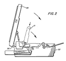
- Figure 2 illustrates the electrostatographic reproducing machine wherein the upper machine frame 33 has been pivoted about machine pivot 35 away from lower machine frame 32 to expose the upper portion of the apparatus.
- the removable processing cartridge is illustrated in solid line in its operational position and also illustrated in dashed line at its initial insert position.
- the removable processing cartridge is mounted as will be discussed hereinafter by inserting it such that the mounting hinge slots on the cartridge engage the locating pivot points on the lower frame of the machine while the mounting pins on the cartridge engage the latch blocks on the lower frame of the machine, thereby enabling the cartridge to be pivoted clockwise from its initial insert position to the operational position as indicated in Figure 2.
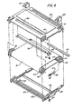
- the removable processing cartridge is illustrated in greater detail in isometric Figure 3 taken together with exploded Figure 4.
- the cartridge assembly 11 comprises an upper cartridge housing 37 and a lower cartridge housing 38, which are fastened together through housing fasteners 56 by a suitable means such as screws 57.
- the mounting arrangement for the cartridge comprises mounting pins 40 on each side of one end of the cartridge assembly here illustrated as the stationary drive shaft for the belt transport roll 43. Both ends of the belt transport roll have end caps 45 positioned thereon with one end being connected through drive gear 46 to the main machine drive to provide positive drive to the belt.
- Mounted adjacent to the mounting pins 40 on both sides of the cartridge are mounting hinge slots 42, the operation of which will be described in greater detail hereinafter.
- an idler roll shaft 53 about which the idler roll 54 is mounted, once again with end caps 45 at each end thereof.
- the photoreceptor belt 12 is transported around transport roll 43 and idler roll 54 through the various processing stations in the two-cycle reproducing apparatus.
- Exposure slot49 permits exposure of the photoreceptor belt from the optical system of the reproducing apparatus.
- erase slot 50 permits the exposure of the photoreceptor during the second cycle of imaging and just prior to cleaning of residual toner image by an erase lamp.
- the upper cartridge housing 37 contains a slot for an image disturber apparatus which may comprise magnet 59 held in magnetic holder 60 fastened to the lower cartridge housing by means of screws 61.
- the removable processing cartridge may contain a corotron such as precharge corotron 64 contained within corotron shield 65.
- the processing cartridge also contains two spring ground contacts 66 for electrically grounding the photoreceptor belt.
- the mounting arrangement contained within the cartridge itself as well as the mounting arrangement contained within the lower machine frame 32 will be described in greater detail. While the mounting arrangement will be generally described with reference to one side of the main frame and cartridge, it will be understood that an identical mount is positioned on the opposite side of the main frame and cartridge.
- the removable processing cartridge contains at one end thereof and adjacent to each other, mounting hinge slots 42 on each side of the cartridge which when the cartridge is inserted into the lower machine frame, engage two machine frame locating pins 68 fixedly attached to lower machine frame 32.
- the cartridge also contains mounting pins 40 at each side thereof, here illustrated as the shaft of transport roll 43 which engage latch blocks 70 on both sides of the lower machine frame 32 which are fixedly attached to the lower machine frame by latch block anchors 72.
- the latch block is provided with a slot 74 through which the mounting pins 40 on the cartridge may be inserted.
- the latch block is designed so as to have a deflectable cantilever spring arm 76 in interference engagement with the mounting pins 40, such that as the mounting pins are forced down into the slot 74 the spring arm 76 is deflected slightly clockwise thereby providing a counterbalancing action to the insertion of the processing cartridge.
- a detent or circular lock portion 77 which fully accommodates the cartridge mounting pins when they reach that point, permitting the cantilever spring arm to return to its undeflected position thereby locking the cartridge in place.
- a guide surface 75 On the other side of the sprang arm is a guide surface 75 which together with the spring arm guides the mounting pins of the photoreceptor cartridge into place.
- the spring arm 76 has a frame stop member 78 to laterally maintain the spring arm in position against the machine lower frame members 32.
- the mounting pins 40 on the cartridge engage the uppermost position of the deflectable cantilever spring arm 76 of the latch block as seen in Figure 5a.
- the cartridge is manually rotated in a clockwise direction to drive the cartridge mounting pins into interference with the upper portion of the deflectable cantilever spring.
- the cartridge continues to be rotated and forced down meeting the resistance of the spring which prevents the cartridge from dropping into the housing thereby causing potential damage to the cartridge or the machine.
- the cantilever spring arm 76 is deflected also in a clockwise position as the mounting pins on the cartridge traverse the slot in the latch block.
- the guide surface 75 maintains the cartridge in its upper position when initially inserted into the receiving mount in the lower machine frame and limits the motion of the cartridge so that it does not back against the adjacent developer housing.
- the latch blocks 70 be made from a suitable plastic material which can be slightly deflected.
- the latch block provides a number of functions.
- the slot with the curved outer deflectable spring acts initially as a limiting stop, then as a cantilever spring counterbalance and finally as a locating member for the mounting pin on the cartridge.
- the stationary inner guide surface prevents the cartridge upon insertion from falling or rotating back on the developer housing.
- the cartridge is mounted such that the end of the photoreceptor belt around the transport roll is in functional cooperation with the developer assembly in the main frame.
- the developer assembly may be biased by a spring, for example, into engagement with the mounting end of the cartridge to form this functional cooperation.
- an additional feature of the present invention resides in the use of a pair of elastomeric U-shaped loops or handles 80 fastened to each side of the processing cartridge at the end of the cartridge away from the mounting end.
- These elastomeric loops 80 function in two respects; as handles and as locking springs. As handles, they are used to lift the removable processing cartridge from its operating position and extract or withdraw it from the lower machine frame. Accordingly the loops should be of sufficient size that a finger may be inserted therein to lift the end of the cartridge from its locked position.
- the loops 80 function when the cartridge is in the operational position and when the upper machine frame 33 has been rotated clockwise into its locked functional position, to urge the cartridge to remain in a fixed plane thereby ensuring that the image plane is in the same position for all imaging functions.
- This is enabled by the elastomeric spring loops contacting the bottom of the optics base pan 90 which is in the upper machine frame 33, so that the cartridge is seated in the operational position at all times by virtue of the compression spring action of the loops.
- the spring force provided should be sufficient to insure that the non-mounting end of the cassette is properly seated in its operational position with the top run of the belt in the focal plane.
- Any suitable elastomeric material may be used as the cartridge positioning loop and handle. Typical materials will be those commercially available materials having acceptable spring characteristics when deflected and include among others commercially available polypropylenes.
- Figure 9 illustrates a preferred embodiment of the spring lifting loops which may be molded from polypropylene forming a single piece spring and lifting loop. This general configuration facilitates molding as well as the design of the appropriate spring force in the piece. In the figure the spring element is slightly depressed by a force without which the spring element would be biased into engagement with the illustrated locking member of the single piece.
- tension is provided in the belt by means illustrated with reference to Figure 4 and additional reference to Figures 7 and 8.
- the belt is tensioned so that the image plane on the top run of the belt, when it is exposed to the document being copied, is uniform across the entire slot. If it is not uniform across the entire slot, at least a portion of the image may be out of focus and there will be a defect in the resultant copy quality. Similarly if the belt is not properly tensioned, difficulty with respect to erratic transfer of the toner image on the photoreceptor belt to the receiving copy sheet may be experienced. To achieve this, at both ends of the photoreceptor idler roll 54 a tensioning arrangement is provided.
- This tensioning arrangement comprises a guide pin 82 which is spring biased by spring means 87 to drive both ends of the idler roll shaft away from the photoreceptor driven roll.
- the guide pin 82 has at one end a pilot pin 84 which fits in hole 85 of idler roll shaft 53, the other end of guide pin 82 residing in slot 88 in the upper housing of the cartridge.
- the spring 87 which is around a portion of the guide pin 82 is biased between stop 89 in the upper cartridge housing and a collar 83 on the guide pin 82 to provide suitable tensioning on both sides of the photoreceptor belt and therefore a uniform imaging plane across the entire exposure slot, and also, a uniform plane for electrostatic transfer of the toner image to the receiving copy sheet.
- the present invention provides a relatively simple, inexpensive, removable processing cartridge for an electrostatic reproducing apparatus. Furthermore a simple, inexpensive mounting means which enables safe replacement of the cartridge in the machine minimizing possible damage to the cartridge, machine, or user is provided.
- the mounting means latch block provides the three functions of a limiting stop member, a counterbalance and a locating or locking member.
- the latch block for example, may be molded from a single piece of molded plastic.
- the present invention provides a cartridge mount wherein the cartridge may be used, inserted and withdrawn with great physical ease.
- the cassette provided herein may be relatively inexpensive for single use or as a disposable item.
Landscapes
- Physics & Mathematics (AREA)
- General Physics & Mathematics (AREA)
- Engineering & Computer Science (AREA)
- Computer Vision & Pattern Recognition (AREA)
- Electrophotography Configuration And Component (AREA)
- Discharging, Photosensitive Material Shape In Electrophotography (AREA)
Description
- The present invention relates to electrostatographic reproducing apparatus and more particularly to a removable processing cartridge for use in such apparatus together with the means to mount the removable processing cartridge in a receiving mount in the reproducing apparatus.
- In the electrostatographic reproducing apparatus commonly in use today, s photoconductive insulating member is typically charged to uniform potential and thereafter exposed to a light image of an original document to be reproduced. The exposure discharges the photoconductive insulating surface in exposed or background areas and creates an electrostatic latent image on the member which corresponds to the image areas contained within the usual document. Subsequently, the electrostatic latent image on the photoconductive insulating surface is made visible by developing the image with developing powder referred to in the art as toner. Most development systems employ a developer material which comprises both charged carrier particles and charged toner particles which triboelectrically adhere to the carrier particles. During development the toner particles are attracted from the carrier particles by the charge pattern of the image areas in the photoconductive insulating area to form a powder image on the photoconductive area. This image may subsequently be transferred to a support surface such as copy paper to which it may be permanently affixed by heating or by the application of pressure.
- The electrostatographic reproducing apparatus commercially available today vary from the 9000 series of products available from Xerox Corporation to the small products in the small volume market designed for use by the casual user. Typical of the small volume products are the 3100 Family of Products available from Xerox Corporation. In each of these machines, the processor section of the reproducing apparatus is divided into at least two frame portions, an upper and lower frame portion which each contain various sections of the processing equipment. Typically the frame portions are hinged or pivoted about one end relative to one another. This machine configuration enables the user to readily attend to any particular machine malfunction such as a copy sheet being jammed in the paper path. As the uses of such automatic reproducing apparatus become more varied, and particularly as the desire for the casual user to use such low volume products has increased, manufacturers have designed smaller and more inexpensive products. To reach the casual user market, it is increasingly important to increase the simplicity and convenience of operation as well as to reduce the cost of operation and replacement. One way in which this may be accomplished is to place one or more electrostatographic processing stations in a replaceable processing cartridge which can be mounted in the frame of the reproducing apparatus. However the conventional hinges, counterbalances, locks, guide members, etc., all conventionally used for mounting such a cartridge, are relatively expensive to manufacture and assemble in a machine. It is accordingly a desire to provide a relatively low cost mount for such removable processing cartridge.
- Furthermore in an attempt to produce a less expensive reproducing copier and one which has very little if any maintenance, it has been suggested to incorporate one or more processing stations of the apparatus in a disposable or removable cartridge. In this way the casual user can readily remove the cartridge when its operational life has been exhausted and insert a new cartridge. This also provides the advantage of being able to use less expensive functional features such as the photoreceptor than in a conventional copier.
- The removable processing cartridges have taken many forms over the years. For example, in the Xerox 914, photoconductor drums have been made removable for years. Furthermore in the Xerox 9000 Family of Products, photoreceptor belts have also been removable. Other replaceable units have been discussed in the prior art, including developer housings, and toner dispensers. Perhaps the ultimate in sophistication of a removable cartridge is that described in U.S. Patent 3,985,436 to (Tanaka et al) wherein a cartridge contains a photoreceptor, a developing device and a cleaning device, as well as a corotron, which cartridge may be releaseably inserted into the copying machine. Such cartridge is positioned in the machine by being inserted from one side thereof and having cooperative elements on the cartridge which are guided by guide members in the main frame of the machine. Figure 3 of this patent illustrates what appear to be rigid handles for handling the cartridge.
- A similar approach is used in the Canon PC 10/ 20, wherein a plastic molded cartridge containing a photoreceptor drum together with other elements including a developer housing and cleaner assembly are inserted from the side of the machine on essentially horizontal guide members to guide the cartridge into its final position in the machine. The Canon PC 10/20 has a rigid molded plastic handle at one side. This side entry requires at least two guide rails in the copier to locate the cartridge. In addition guide pins are required to accurately locate the cartridge.
- Most of the automatic reproducing apparatus available in the prior art has used various separate stations for charging, exposing, developing, transferring and cleaning and discharging functions disposed about the photoconductive member. However the complexity and associated cost of the reproducing machine may be significantly reduced if the various separate functions are combined to form dual functions. Various attempts have been made to achieve this by combining units in an electrostatographic machine. For example, U.S. Patent 3,637,306 to Cooper describes such a machine with a combined developing/cleaning unit which is operable to perform either function at the proper time during the copying sequence. U.S. Patent 3,647,293 to Queener, describes a similar combined development/cleaning unit and U.S. Patent 4,087,170 to Sawaoka et al describes a copying machine wherein the charge/transfer, exposure/ discharge and developing/clean units are dual units to perform the indicated dual functions. During the first rotation of the drum charging, exposure and development are effected and in the second rotation of the drum transfer, discharge and cleaning are achieved. And finally in U.S. Patent 4,372,669 to Fantuzzo et al., a two-cycle machine employing a photoconductive belt arranged in a recirculating path which is used with a combined charging/transfer unit and a combined developing/cleaning unit is provided.
- The present invention is intended to provide a removable processing cartridge for electrostatographic apparatus, as well as the electrostatographic apparatus comprising same, which is simplex and more convenient to use than the known cartridges, and which is less costly to operate and replace. The invention accordingly provides a cartridge which is characterised in that the mounting means on the cartridge comprises a pair of mounting hinge slots, one on each side of one end of said cartridge which are positioned for cooperative engagement with a pair of locating pivot pins located one on each side of the frame of the reproducing apparatus about which said cartridge may be pivoted and, a pair of mounting pins one on each side of one end of said cartridge adjacent said mounting hinge slots which pins are positioned for cooperative engagement with a pair of cartridge latch blocks located one on each side of the frame of the reproducing apparatus.
- The invention also provides an electrostatographic reproduction apparatus comprising a main frame, a removable processing cartridge containing at least one electrostatographic processing unit, a cartridge mounting means attached to the main frame of said reproducing apparatus which comprises a pair of locating pivot pins one on each side of the main frame and a pair of cartridge latch blocks adjacent said locating pivot pins one on each side of the frame; and cartridge mounting means attached to said cartridge comprising a pair of mounting hinge slots one on each side of one end of said cartridge which are positioned for cooperative engagement with the pair of locating pivot pins on the main frame, and a pair of mounting pins one on each side of one end of said cartridge adjacent said ' mounting hinge slots which are positioned for cooperative engagement with a pair of cartridge latch blocks on the main frame of the reproducing apparatus.
- In a specific aspect of the present invention, the cartridge latch blocks have arcuate slots therein defining a stationary inner guide surface and a curved outer deflectable cantilever spring arm, such slots terminating at its lower portion in a cartridge lock for said cartridge mounting pins and wherein said cartridges may be initially inserted in said mount with said cartridge hinge slot resting on said main frame locating pivot pins, said cartridge mounting pins engage the upper end of said curved outer deflectable cantilever spring arm, and as said cartridge is pivoted about said locating pivot pins said spring arm provides an interference for said cartridge mounting pins and is deflected thereby providing a counterbalance to said cartridge as it is lowered to its operative position.
- In a further aspect of the present invention, the cartridge lock comprises a circular portion which accommodates the cartridge mounting pins which when in position, permit the cantilever spring arm to return to its undeflected position when said mounting pins are in said circular position thereby locking said cartridge in position.
- In a further aspect of the present invention the reproducing apparatus comprises a lower and upper frame portion pivotable about one end in a clam-shell fashion and wherein the cartridge mounting means are attached to said lower frame portion and the cartridge can be inserted from the top into the cartridge mounting means only when said upper frame portion is pivoted to an open position.
- In a further aspect of the present invention, the removable processing cartridge comprises a photoreceptor belt positioned and driven around a driven transport roll and a support roll together with a corona charging device, an exposure slot for exposing the charged photoreceptor belt and a drive gear mounted on one of said photoreceptor transport roll which engages with the main drive of the machine when the cartridge is in the operative position in the reproducing apparatus.
- The present invention provides a compact and inexpensive means to mount the removable processing cartridge in the frame of an electrostatographic reproducing apparatus.
- A removable processing cartridge, in an electrostatographic reproducing apparatus, in accordance with the invention will now be described, by way of example, with reference to the accompanying drawings, in which:-
- Figure 1 is a schematic representation in cross- section of an automatic electrostatographic reproducing machine with the removable processing cartridge and mount therefor according to the present invention included therein.
- Figure 2 is a schematic representation in cross- section of the automatic electrostatographic reproducing machine with the clam-shell opened and the removable processing cartridge in the upright loading position.
- Figure 3 is an isometric view showing the removable processing cartridge according to the present invention.
- Figure 4 is an exploded view of the removable processing cartridge according to the present invention.
- Figures 5a, 5b, 5c are each side views showing the removable processing cartridge mount used according to the present invention. In Figure 5a, the cartridge has been inserted in the mount in the machine frame from the substantially upright position. In Figure 5b, the cartridge is pivoted about the locating pivot pins on the machine frame with the mounting pins of the cartridge engaging the deflectable cantilever spring arms of the latch blocks on the main frame. Figure 5c shows the cartridge locked in place in its operational position in the cartridge mount.
- Figure 6 is an enlarged isometric view of the latch block positioned on the machine frame for inserting the cartridge therein.
- Figure 7 is a side view of the belt tensioning device and lifting handles.
- Figure 8 is a top view, partly cut away, of the machine and cartridge mounts with the cartridge in position.
- Figure 9 is an isometric view of a preferred embodiment of the lifting or spring handles on the cassette illustrating the spring portion to be slightly depressed by a force.
- Referring now to Figure 1 there is shown by way of example an automatic xerographic machine 10 which includes the removable processing cartridge and cartridge mount of the present invention. The reproducing machine 10 depicted in Figure 1 illustrates the various components utilized therein for producing copies from an original document. Although the apparatus of the present invention is particularly well adapted for use in an automatic xerographic reproducing machine 10, it should become evident from the following description that it is equally well suited for use in a wide variety of processing systems including other electrostatographic systems and it is not necessarily limited in application to the particular embodiment or embodiments shown herein.
- The automatic reproducing machine 10 is adapted to operate in two cycle fashion in that the photoreceptor belt is charged, exposed and the resulting electrostatic latent image developed on the first cycle of the belt while the developed toner image on the belt is transferred to a copy sheet as the belt begins its second revolution through the processing stations. Thereafter in the second cycle of operation the belt is cleaned of residual toner by the developer station in preparation for producing the next copy. With this two-cycle geometry a combined charging/transfer unit and a combined developer/cleaning unit are used.
- The reproducing machine 10, illustrated in Figures 1 and 2 employs a removable processing cartridge 11, image recording belt like
member 12, the outer periphery of which is coated with a suitablephotoconductive material 13. Thebelt 12 is suitably mounted for revolution within the cartridge about driventransport roll 43 andidler roll 54 and travels in the direction indicated byarrow 15 to bring the image-bearingsurface 13 thereon past a plurality of xerographic processing stations. Suitable drive means (not shown) are provided to power and coordinate the motion of the various cooperating machine components whereby a faithful reproduction of the original input scene information is recorded upon a sheet offinal support material 16 such as paper or the like. - Initially, the
belt 12 moves thephotoconductive surface 13 through a charging/transfer station 17 where in the first cycle, the belt is charged with an electrostatic charge uniformly placed over thephotoconductive surface 13 in known manner preparatory to imaging. Thereafter, thebelt 12 is driven toexposure station 14 where the chargedphotoconductive surface 13 is exposed to a light image of the original input scene information whereby the charge is selectively dissipated in the light exposed regions to record the original input scene in the form of an electrostatic latent image. The exposure station preferably comprises a bundle of image transmittingfiber lenses 18, produced under the tradename of "SELFOC" by Nippon Sheet Glass Company, Limited, together with an illuminatinglamp 23 andreflector 26. After exposure thebelt 12 transports the electrostatic latent image recorded on thephotoconductive surface 13 to development/cleaning station 19 wherein a developer is applied to the photoconductive surface of thedrum 12 rendering the latent image visible. Typically a suitable development station could include a magnetic brush development system utilizing a magnitizable developer mix having coarse ferromagnetic carrier granules and toner colorant particles. -
Sheets 16 of the final support material are supported in a stack arrangement on an elevatingstack support tray 20. With the stack at its elevated position a sheet separator segmented feed roll 21 feeds individual sheets therefrom to the registration pinch rolls 22. The sheet is then forwarded to the charging/transfer station 17 in proper registration with the image on the belt and the developed image on thephotoconductive surface 13 is brought into contact with thesheet 16 of final support material within the charging/ transfer station 17 and the toner image is transferred from thephotoconductive surface 13 to the contacting side of thefinal support sheet 16. Following transfer of the image the final support material which may be paper, plastic, etc., as desired is separated from the belt by the beam strength of thesupport material 16 and, the sheet with the toner image thereon is advanced to a suitable fuser such asroll fuser 24 which fixes the transferred powder image thereto. After the fusing process thesheet 16 is advanced to a suitable output device such astray 25. - Although a preponderance of toner powder is transferred to the
final support material 16, invariably some residual toner remains on thephotoconductive surface 13 after the transfer of the toner powder image to the final support material. The residual toner particles remaining on thephotoconductive surface 13 after the transfer operation are removed from thebelt 12 as it moves in its second cycle through the developing/ cleaningstation 19 where the toner particles may be mechanically cleaned from thephotoconductive surface 13 by the same magnetic brush as used in developing the electrostatic latent image. To assist in cleaning thebelt 12 of the residual toner, a toner particle disturber which may comprise abar magnet 59 under the belt is positioned to gently disturb the location of the individual toner particles thereby facilitating subsequent cleaning. - Normally, when the copier is operated in a conventional mode, the original document to be reproduced is placed image side down upon a horizontal
transparent viewing platen 30 which transports the original past an optical arrangement here illustrated asSelfoc lens 18. The speed of the moving platen and the speed of the photoconductive belt are synchronized to provide a faithful reproduction of the original document. - It is believed that the foregoing general description is sufficient for the purposes of the present application to illustrate the general operation of an automatic xerographic copier 10 which can embody the apparatus in accordance with the present invention.
- Figure 2 illustrates the electrostatographic reproducing machine wherein the
upper machine frame 33 has been pivoted aboutmachine pivot 35 away fromlower machine frame 32 to expose the upper portion of the apparatus. The removable processing cartridge is illustrated in solid line in its operational position and also illustrated in dashed line at its initial insert position. The removable processing cartridge is mounted as will be discussed hereinafter by inserting it such that the mounting hinge slots on the cartridge engage the locating pivot points on the lower frame of the machine while the mounting pins on the cartridge engage the latch blocks on the lower frame of the machine, thereby enabling the cartridge to be pivoted clockwise from its initial insert position to the operational position as indicated in Figure 2. - The removable processing cartridge is illustrated in greater detail in isometric Figure 3 taken together with exploded Figure 4. The cartridge assembly 11 comprises an
upper cartridge housing 37 and alower cartridge housing 38, which are fastened together throughhousing fasteners 56 by a suitable means such as screws 57. The mounting arrangement for the cartridge comprises mountingpins 40 on each side of one end of the cartridge assembly here illustrated as the stationary drive shaft for thebelt transport roll 43. Both ends of the belt transport roll haveend caps 45 positioned thereon with one end being connected throughdrive gear 46 to the main machine drive to provide positive drive to the belt. Positioned adjacent to the mounting pins 40 on both sides of the cartridge are mountinghinge slots 42, the operation of which will be described in greater detail hereinafter. At the other end of the cartridge assembly is anidler roll shaft 53 about which theidler roll 54 is mounted, once again withend caps 45 at each end thereof. Thephotoreceptor belt 12 is transported aroundtransport roll 43 andidler roll 54 through the various processing stations in the two-cycle reproducing apparatus. In addition to the removable processing cartridge being equipped with the photoreceptor belt it may also have additional electrostatographic processing units and functions contained therein. Exposure slot49 permits exposure of the photoreceptor belt from the optical system of the reproducing apparatus. Furthermore eraseslot 50 permits the exposure of the photoreceptor during the second cycle of imaging and just prior to cleaning of residual toner image by an erase lamp. In addition, theupper cartridge housing 37 contains a slot for an image disturber apparatus which may comprisemagnet 59 held inmagnetic holder 60 fastened to the lower cartridge housing by means of screws 61. In addition and with particular reference to Figure 4, the removable processing cartridge may contain a corotron such asprecharge corotron 64 contained withincorotron shield 65. The processing cartridge also contains twospring ground contacts 66 for electrically grounding the photoreceptor belt. - With further reference to Figures 5a, 5b, 5c, and Figure 6, the mounting arrangement contained within the cartridge itself as well as the mounting arrangement contained within the
lower machine frame 32 will be described in greater detail. While the mounting arrangement will be generally described with reference to one side of the main frame and cartridge, it will be understood that an identical mount is positioned on the opposite side of the main frame and cartridge. The removable processing cartridge contains at one end thereof and adjacent to each other, mountinghinge slots 42 on each side of the cartridge which when the cartridge is inserted into the lower machine frame, engage two machine frame locating pins 68 fixedly attached tolower machine frame 32. The cartridge also contains mountingpins 40 at each side thereof, here illustrated as the shaft oftransport roll 43 which engage latch blocks 70 on both sides of thelower machine frame 32 which are fixedly attached to the lower machine frame by latch block anchors 72. The latch block is provided with aslot 74 through which the mounting pins 40 on the cartridge may be inserted. In addition, the latch block is designed so as to have a deflectablecantilever spring arm 76 in interference engagement with the mounting pins 40, such that as the mounting pins are forced down into theslot 74 thespring arm 76 is deflected slightly clockwise thereby providing a counterbalancing action to the insertion of the processing cartridge. At the end of theslot 74 there is a detent orcircular lock portion 77 which fully accommodates the cartridge mounting pins when they reach that point, permitting the cantilever spring arm to return to its undeflected position thereby locking the cartridge in place. On the other side of the sprang arm is aguide surface 75 which together with the spring arm guides the mounting pins of the photoreceptor cartridge into place. Also attached and as may be more clearly illustrated in Figure 6, thespring arm 76 has aframe stop member 78 to laterally maintain the spring arm in position against the machinelower frame members 32. - With continued reference to Figure 5a, 5b and 5c and with particular reference to the directional arrows for both the cartridge as a whole as well as for the movement of the
cartridge mounting pin 40 in theslot 74 of thelatch block 70, together with this movement in a clockwise direction, the insertion of the cartridge will be described in greater detail. For the cartridge to be inserted in its operational position, theupper machine frame 33 must be rotated in a counterclockwise direction aboutpivot point 35 thereby creating an open space betweenupper machine frame 33 andlower machine frame 32. The cartridge is manually positioned in an almost vertical orientation such that the mountinghinge slots 42 on each side of the cartridge are placed on the locating pivot pins 68 on each side of the lower machine frame. At this time the mounting pins 40 on the cartridge engage the uppermost position of the deflectablecantilever spring arm 76 of the latch block as seen in Figure 5a. Once in this position the cartridge is manually rotated in a clockwise direction to drive the cartridge mounting pins into interference with the upper portion of the deflectable cantilever spring. The cartridge continues to be rotated and forced down meeting the resistance of the spring which prevents the cartridge from dropping into the housing thereby causing potential damage to the cartridge or the machine. As the cartridge is rotated in a clockwise direction illustrated further in Figure 5b, thecantilever spring arm 76 is deflected also in a clockwise position as the mounting pins on the cartridge traverse the slot in the latch block. Finally the mounting pins 40 are forced over the final interference of the spring arm into the circular detent orlock portion 77 and the cantilevered spring arm is free to snap back into its original position thereby producing a torque about the pivot pins which is the force which holds the entire cartridge assembly into its exact location and ensures that thedrive gear 46 is perfectly in mesh with the main drive gear mounted in the machine frame. In other words the cartridge pivots into place about the fixed pivot pins about which it is fixedly positioned through interaction with the mounting hinge slots. When the mounting pins 40 on the cartridge are forced over the final interference of the spring arm, the spring force creates the torque which tends to drive the opposite (non-mounting) end down into position. Theguide surface 75 maintains the cartridge in its upper position when initially inserted into the receiving mount in the lower machine frame and limits the motion of the cartridge so that it does not back against the adjacent developer housing. To facilitate the above described functions of the deflectable cantilever spring, it is desirable that the latch blocks 70 be made from a suitable plastic material which can be slightly deflected. - Accordingly the latch block provides a number of functions. The slot with the curved outer deflectable spring acts initially as a limiting stop, then as a cantilever spring counterbalance and finally as a locating member for the mounting pin on the cartridge. Furthermore the stationary inner guide surface prevents the cartridge upon insertion from falling or rotating back on the developer housing. In this connection it should be noted that in the machine configuration depicted the cartridge is mounted such that the end of the photoreceptor belt around the transport roll is in functional cooperation with the developer assembly in the main frame. The developer assembly may be biased by a spring, for example, into engagement with the mounting end of the cartridge to form this functional cooperation.
- With continued reference to Figures 3 and 4 and further reference to Figure 7, an additional feature of the present invention resides in the use of a pair of elastomeric U-shaped loops or handles 80 fastened to each side of the processing cartridge at the end of the cartridge away from the mounting end. These
elastomeric loops 80 function in two respects; as handles and as locking springs. As handles, they are used to lift the removable processing cartridge from its operating position and extract or withdraw it from the lower machine frame. Accordingly the loops should be of sufficient size that a finger may be inserted therein to lift the end of the cartridge from its locked position. As springs theloops 80 function when the cartridge is in the operational position and when theupper machine frame 33 has been rotated clockwise into its locked functional position, to urge the cartridge to remain in a fixed plane thereby ensuring that the image plane is in the same position for all imaging functions. This is enabled by the elastomeric spring loops contacting the bottom of theoptics base pan 90 which is in theupper machine frame 33, so that the cartridge is seated in the operational position at all times by virtue of the compression spring action of the loops. The spring force provided should be sufficient to insure that the non-mounting end of the cassette is properly seated in its operational position with the top run of the belt in the focal plane. Any suitable elastomeric material may be used as the cartridge positioning loop and handle. Typical materials will be those commercially available materials having acceptable spring characteristics when deflected and include among others commercially available polypropylenes. - Figure 9 illustrates a preferred embodiment of the spring lifting loops which may be molded from polypropylene forming a single piece spring and lifting loop. This general configuration facilitates molding as well as the design of the appropriate spring force in the piece. In the figure the spring element is slightly depressed by a force without which the spring element would be biased into engagement with the illustrated locking member of the single piece.
- To further maintain the photoreceptor belt in a fixed focal plane, tension is provided in the belt by means illustrated with reference to Figure 4 and additional reference to Figures 7 and 8. The belt is tensioned so that the image plane on the top run of the belt, when it is exposed to the document being copied, is uniform across the entire slot. If it is not uniform across the entire slot, at least a portion of the image may be out of focus and there will be a defect in the resultant copy quality. Similarly if the belt is not properly tensioned, difficulty with respect to erratic transfer of the toner image on the photoreceptor belt to the receiving copy sheet may be experienced. To achieve this, at both ends of the photoreceptor idler roll 54 a tensioning arrangement is provided. This tensioning arrangement comprises a
guide pin 82 which is spring biased by spring means 87 to drive both ends of the idler roll shaft away from the photoreceptor driven roll. Theguide pin 82 has at one end apilot pin 84 which fits inhole 85 ofidler roll shaft 53, the other end ofguide pin 82 residing inslot 88 in the upper housing of the cartridge. Thespring 87 which is around a portion of theguide pin 82 is biased betweenstop 89 in the upper cartridge housing and acollar 83 on theguide pin 82 to provide suitable tensioning on both sides of the photoreceptor belt and therefore a uniform imaging plane across the entire exposure slot, and also, a uniform plane for electrostatic transfer of the toner image to the receiving copy sheet. - Thus, it may be readily appreciated by reference to the foregoing description when taken with the drawings that the present invention provides a relatively simple, inexpensive, removable processing cartridge for an electrostatic reproducing apparatus. Furthermore a simple, inexpensive mounting means which enables safe replacement of the cartridge in the machine minimizing possible damage to the cartridge, machine, or user is provided. The mounting means latch block provides the three functions of a limiting stop member, a counterbalance and a locating or locking member. In addition, it readily lends itself to manufacture with inexpensive plastic molded parts and requires a minimum of functional parts and assembly time. The latch block, for example, may be molded from a single piece of molded plastic. In addition, the present invention provides a cartridge mount wherein the cartridge may be used, inserted and withdrawn with great physical ease. Finally the cassette provided herein may be relatively inexpensive for single use or as a disposable item.
- While the invention has been described with reference to specific embodiments it will be apparent to those skilled in the art that many alternatives, modifications and variations may be made. For example, while the removable cartridge has been described as including a photoreceptor belt, a corotron, an image disturber, two exposure slots, one or more of these features could be omitted as well as additional features beinq added to the cartridqe.
Claims (10)
Applications Claiming Priority (2)
| Application Number | Priority Date | Filing Date | Title |
|---|---|---|---|
| US06/614,201 US4556308A (en) | 1984-05-25 | 1984-05-25 | Removable processing cartridge for electrostatographic reproducing apparatus |
| US614201 | 1984-05-25 |
Publications (3)
| Publication Number | Publication Date |
|---|---|
| EP0163486A2 EP0163486A2 (en) | 1985-12-04 |
| EP0163486A3 EP0163486A3 (en) | 1986-08-27 |
| EP0163486B1 true EP0163486B1 (en) | 1990-05-23 |
Family
ID=24460256
Family Applications (1)
| Application Number | Title | Priority Date | Filing Date |
|---|---|---|---|
| EP85303620A Expired EP0163486B1 (en) | 1984-05-25 | 1985-05-22 | Removable processing cartridge for electrostatographic reproducing apparatus |
Country Status (6)
| Country | Link |
|---|---|
| US (1) | US4556308A (en) |
| EP (1) | EP0163486B1 (en) |
| JP (1) | JPS60260063A (en) |
| DE (1) | DE3577932D1 (en) |
| ES (1) | ES8607578A1 (en) |
| MX (1) | MX161410A (en) |
Families Citing this family (36)
| Publication number | Priority date | Publication date | Assignee | Title |
|---|---|---|---|---|
| US4657369A (en) * | 1985-04-02 | 1987-04-14 | Kentek Information Systems, Inc. | Disposable photoconductive belt assembly for a printer or a copier |
| JPS62156671A (en) * | 1985-12-27 | 1987-07-11 | Sharp Corp | Cartridge device for image forming device |
| DE3684269D1 (en) * | 1985-12-27 | 1992-04-16 | Sharp Kk | PHOTO RECEPTOR CASSETTE. |
| US4655578A (en) * | 1986-03-24 | 1987-04-07 | Xerox Corporation | Reproducing apparatus cartridge mounting assembly |
| JPH07104627B2 (en) * | 1986-04-23 | 1995-11-13 | アルプス電気株式会社 | Electrophotographic printer |
| GB2197258B (en) * | 1986-09-05 | 1991-05-22 | Ricoh Kk | Electrostatic recording apparatus |
| US4862212A (en) * | 1987-03-03 | 1989-08-29 | Ricoh Company, Ltd. | Image forming apparatus |
| US4786937A (en) * | 1987-05-01 | 1988-11-22 | Xerox Corporation | Processing cartridge with one time function sheet |
| US4959731A (en) * | 1987-06-09 | 1990-09-25 | Kentek Informatio Systems, Inc. | Combined electrographic printer, copier, and telefax machine |
| US4754300A (en) * | 1987-06-09 | 1988-06-28 | Kentek Information Systems, Inc. | Combined electrographic printer, copier, and telefax machine |
| US4804993A (en) * | 1987-08-05 | 1989-02-14 | Eastman Kodak Company | Photoconductive member mounting mechanism for an electrophotographic reproduction apparatus |
| US5099280A (en) * | 1987-10-30 | 1992-03-24 | Mita Industrial Co., Ltd. | Cleaning unit of a copying apparatus |
| US5155526A (en) * | 1988-07-07 | 1992-10-13 | Minolta Camera Kabushiki Kaisha | Electrophotographic copying apparatus having axially aligned developing elements |
| US4912510A (en) * | 1988-08-17 | 1990-03-27 | Sharp Kabushiki Kaisha | Image forming apparatus with detachable cartridge |
| JP2678379B2 (en) * | 1988-11-11 | 1997-11-17 | 三田工業 株式会社 | Image forming device |
| US4987446A (en) * | 1988-12-15 | 1991-01-22 | Ricoh Company, Ltd. | Process unit cartridge for an electrophotographic apparatus |
| US5136333A (en) * | 1989-06-30 | 1992-08-04 | Lexmark International, Inc. | Electrophotographic printer and cartridge arrangement |
| EP0425227A3 (en) * | 1989-10-24 | 1992-09-02 | Konica Corporation | Image recording apparatus |
| JPH0369153U (en) * | 1989-11-09 | 1991-07-09 | ||
| EP0496400B1 (en) * | 1991-01-25 | 1997-05-28 | Canon Kabushiki Kaisha | Electrophotographic image forming apparatus with a process cartridge mounting feature |
| US5257071A (en) * | 1991-05-24 | 1993-10-26 | Eastman Kodak Company | Pivotal photoconductor belt assembly |
| US5233388A (en) * | 1991-09-06 | 1993-08-03 | Xerox Corporation | Apparatus for controlling belt guidance in an electrophotographic printing machine |
| US5228671A (en) * | 1992-11-20 | 1993-07-20 | Xerox Corporation | Sheet feeder with single sheet bypass |
| US5331388A (en) * | 1992-12-28 | 1994-07-19 | Xerox Corporation | Simple reliable counter assembly of reduced parts for a toner cartridge |
| US5341200A (en) * | 1992-12-28 | 1994-08-23 | Xerox Corporation | Removable process unit with waste toner storage |
| JPH06317953A (en) * | 1993-04-28 | 1994-11-15 | Canon Inc | Frame structure and image forming device |
| US5452066A (en) * | 1993-11-26 | 1995-09-19 | Xerox Corporation | Shutter seal assembly |
| JP3337859B2 (en) * | 1994-04-26 | 2002-10-28 | キヤノン株式会社 | Process cartridge and image forming apparatus |
| US5583618A (en) * | 1994-05-31 | 1996-12-10 | Matsushita Electric Industrial Co., Ltd. | Process cartridge and image generating apparatus |
| JP3453450B2 (en) * | 1995-04-26 | 2003-10-06 | キヤノン株式会社 | Removable guide member and image forming apparatus |
| US5881341A (en) * | 1997-11-14 | 1999-03-09 | Xerox Corporation | Printing cartridge with molded cantilever developer roller spacing spring |
| JP3514618B2 (en) * | 1997-11-28 | 2004-03-31 | 株式会社リコー | Image forming device |
| US6984144B1 (en) | 2004-12-22 | 2006-01-10 | Xerox Corporation | Low effort, high reliability quick coupling mechanism |
| US7418766B2 (en) * | 2004-12-22 | 2008-09-02 | Xerox Corporation | Hinge with tandem pivot structure motion lock and override |
| JP5064999B2 (en) * | 2007-12-27 | 2012-10-31 | キヤノン株式会社 | Sheet processing device |
| KR20090105044A (en) * | 2008-04-01 | 2009-10-07 | 삼성전자주식회사 | Image forming apparatus and image forming apparatus having same |
Family Cites Families (20)
| Publication number | Priority date | Publication date | Assignee | Title |
|---|---|---|---|---|
| US3647293A (en) * | 1970-12-01 | 1972-03-07 | Ibm | Copying system featuring combined developing-cleaning station alternately activated |
| US3637306A (en) * | 1970-12-02 | 1972-01-25 | Ibm | Copying system featuring alternate developing and cleaning of successive image areas on photoconductor |
| US3883242A (en) * | 1970-12-29 | 1975-05-13 | Canon Kk | Electronic photographic copying machine |
| DE2341531B2 (en) * | 1973-08-16 | 1978-10-12 | Develop Dr. Eisbein Gmbh & Co, 7016 Gerlingen | Copier with a device for developing and fixing a charge image transferred to a copy carrier |
| US3985436A (en) * | 1974-06-25 | 1976-10-12 | Minolta Camera Kabushiki Kaisha | Electrophotographic copying apparatus |
| DE2436301A1 (en) * | 1974-07-27 | 1976-02-12 | Agfa Gevaert Ag | ELECTROSTATIC COPY DEVICE |
| JPS5188229A (en) * | 1975-01-31 | 1976-08-02 | Fukushakino kankodoramugaidosochi | |
| GB1535398A (en) * | 1975-06-13 | 1978-12-13 | Tokyo Shibaura Electric Co | Electrostatic copying apparatus |
| JPS5275444A (en) * | 1975-12-19 | 1977-06-24 | Minolta Camera Co Ltd | Electrophotographic copying machine |
| US4114998A (en) * | 1977-01-14 | 1978-09-19 | Tokyo Shibaura Electric Co., Ltd. | Copying machine with removable photosensitive drum |
| US4264199A (en) * | 1979-02-12 | 1981-04-28 | Coulter Systems Corporation | Unitary optical system mounting component for imaging apparatus |
| US4236807A (en) * | 1979-02-12 | 1980-12-02 | Coulter Systems Corporation | Modular electrophotographic copying machine |
| US4271786A (en) * | 1980-06-16 | 1981-06-09 | Pitney-Bowes, Inc. | Electrophotocopier developer unit mounting system |
| JPS5778075A (en) * | 1980-10-31 | 1982-05-15 | Toshiba Corp | Photoreceptor holding device for picture forming equipment |
| DE3047706C2 (en) * | 1980-12-18 | 1985-01-17 | Canon K.K., Tokio/Tokyo | Electrophotographic copier |
| US4432632A (en) * | 1981-01-13 | 1984-02-21 | Ricoh Company, Ltd. | Apparatus for holding a recording member in the form of an endless belt in a recording system using the same |
| US4372669A (en) * | 1981-06-29 | 1983-02-08 | Xerox Corporation | Electrophotographic printing machine |
| US4470690A (en) * | 1981-10-22 | 1984-09-11 | Tetras, S.A. | Removably mounted electrophotographic belt assembly for electrophotographic copier |
| US4416532A (en) * | 1982-06-11 | 1983-11-22 | International Business Machines Corporation | Latching and tensioning mechanism for closed-loop belt supporting capstan |
| US4544260A (en) * | 1984-05-25 | 1985-10-01 | Xerox Corporation | Removable processing cartridge for electrostatographic reproducing apparatus |
-
1984
- 1984-05-25 US US06/614,201 patent/US4556308A/en not_active Expired - Fee Related
-
1985
- 1985-05-17 MX MX205332A patent/MX161410A/en unknown
- 1985-05-17 JP JP60105771A patent/JPS60260063A/en active Pending
- 1985-05-22 DE DE8585303620T patent/DE3577932D1/en not_active Expired - Fee Related
- 1985-05-22 EP EP85303620A patent/EP0163486B1/en not_active Expired
- 1985-05-24 ES ES543467A patent/ES8607578A1/en not_active Expired
Also Published As
| Publication number | Publication date |
|---|---|
| DE3577932D1 (en) | 1990-06-28 |
| EP0163486A3 (en) | 1986-08-27 |
| JPS60260063A (en) | 1985-12-23 |
| EP0163486A2 (en) | 1985-12-04 |
| US4556308A (en) | 1985-12-03 |
| MX161410A (en) | 1990-09-21 |
| ES543467A0 (en) | 1986-06-16 |
| ES8607578A1 (en) | 1986-06-16 |
Similar Documents
| Publication | Publication Date | Title |
|---|---|---|
| US4556308A (en) | Removable processing cartridge for electrostatographic reproducing apparatus | |
| US4544260A (en) | Removable processing cartridge for electrostatographic reproducing apparatus | |
| US5095335A (en) | Copier with retractable charging unit to prevent damage to drum when removing process cartridge | |
| US4335950A (en) | Frame assembly with upper and lower frame members for automatic reproducing apparatus | |
| US5105221A (en) | Image forming apparatus having detachable optical and processing units | |
| EP0251823B1 (en) | Waste toner collecting system | |
| EP0166871B1 (en) | Electrostatic copying apparatus | |
| US7715746B2 (en) | Process cartridge having electrical contact and image forming apparatus having electrical contact in urging member | |
| US4924267A (en) | Process cartridge and multi-color image forming apparatus using same | |
| EP1184742B1 (en) | Image forming apparatus and developer supply container removably mountable in image forming apparatus | |
| US4655578A (en) | Reproducing apparatus cartridge mounting assembly | |
| US4908661A (en) | Holder device for handling an image carrier of an image forming apparatus | |
| US4916490A (en) | Image forming apparatus comprising a plurality of developing devices | |
| JP2003084647A (en) | Image forming apparatus and developing unit | |
| US4630919A (en) | Selectable color system | |
| US4465359A (en) | Portable electrophotographic copying apparatus | |
| JPS5926745A (en) | Image forming device | |
| US5005053A (en) | Image-forming machine having a process assembly comprising two independently movable units | |
| JP2007057953A (en) | Image forming apparatus | |
| EP0230033B1 (en) | Cartridge unit for use in an image forming apparatus | |
| JPS61110168A (en) | Image forming device | |
| JP2659717B2 (en) | Image forming unit attaching / detaching device in image forming apparatus | |
| US5227841A (en) | Image forming apparatus having unit support member thereon | |
| US4827308A (en) | Process unit for an imaging apparatus | |
| US5584471A (en) | Reproduction machine having a user clearable convenience stapler assembly |
Legal Events
| Date | Code | Title | Description |
|---|---|---|---|
| PUAI | Public reference made under article 153(3) epc to a published international application that has entered the european phase |
Free format text: ORIGINAL CODE: 0009012 |
|
| AK | Designated contracting states |
Designated state(s): BE DE FR GB IT |
|
| PUAL | Search report despatched |
Free format text: ORIGINAL CODE: 0009013 |
|
| AK | Designated contracting states |
Kind code of ref document: A3 Designated state(s): BE DE FR GB IT |
|
| 17P | Request for examination filed |
Effective date: 19870211 |
|
| 17Q | First examination report despatched |
Effective date: 19880810 |
|
| GRAA | (expected) grant |
Free format text: ORIGINAL CODE: 0009210 |
|
| AK | Designated contracting states |
Kind code of ref document: B1 Designated state(s): BE DE FR GB IT |
|
| REF | Corresponds to: |
Ref document number: 3577932 Country of ref document: DE Date of ref document: 19900628 |
|
| ET | Fr: translation filed | ||
| ITF | It: translation for a ep patent filed | ||
| PLBE | No opposition filed within time limit |
Free format text: ORIGINAL CODE: 0009261 |
|
| STAA | Information on the status of an ep patent application or granted ep patent |
Free format text: STATUS: NO OPPOSITION FILED WITHIN TIME LIMIT |
|
| 26N | No opposition filed | ||
| ITTA | It: last paid annual fee | ||
| PGFP | Annual fee paid to national office [announced via postgrant information from national office to epo] |
Ref country code: FR Payment date: 19930222 Year of fee payment: 9 |
|
| PGFP | Annual fee paid to national office [announced via postgrant information from national office to epo] |
Ref country code: DE Payment date: 19930319 Year of fee payment: 9 |
|
| PGFP | Annual fee paid to national office [announced via postgrant information from national office to epo] |
Ref country code: BE Payment date: 19930323 Year of fee payment: 9 |
|
| PGFP | Annual fee paid to national office [announced via postgrant information from national office to epo] |
Ref country code: GB Payment date: 19930414 Year of fee payment: 9 |
|
| PG25 | Lapsed in a contracting state [announced via postgrant information from national office to epo] |
Ref country code: GB Effective date: 19940522 |
|
| PG25 | Lapsed in a contracting state [announced via postgrant information from national office to epo] |
Ref country code: BE Effective date: 19940531 |
|
| BERE | Be: lapsed |
Owner name: XEROX CORP. Effective date: 19940531 |
|
| GBPC | Gb: european patent ceased through non-payment of renewal fee |
Effective date: 19940522 |
|
| PG25 | Lapsed in a contracting state [announced via postgrant information from national office to epo] |
Ref country code: FR Effective date: 19950131 |
|
| PG25 | Lapsed in a contracting state [announced via postgrant information from national office to epo] |
Ref country code: DE Effective date: 19950201 |
|
| REG | Reference to a national code |
Ref country code: FR Ref legal event code: ST |