EP0161381B1 - Equipment for the lateral transference of pipes - Google Patents
Equipment for the lateral transference of pipes Download PDFInfo
- Publication number
- EP0161381B1 EP0161381B1 EP84830365A EP84830365A EP0161381B1 EP 0161381 B1 EP0161381 B1 EP 0161381B1 EP 84830365 A EP84830365 A EP 84830365A EP 84830365 A EP84830365 A EP 84830365A EP 0161381 B1 EP0161381 B1 EP 0161381B1
- Authority
- EP
- European Patent Office
- Prior art keywords
- pipe
- shaft
- roller
- roller track
- end portion
- Prior art date
- Legal status (The legal status is an assumption and is not a legal conclusion. Google has not performed a legal analysis and makes no representation as to the accuracy of the status listed.)
- Expired
Links
- 238000005096 rolling process Methods 0.000 description 7
- 238000004519 manufacturing process Methods 0.000 description 2
- 239000000428 dust Substances 0.000 description 1
- 230000009347 mechanical transmission Effects 0.000 description 1
- 230000007246 mechanism Effects 0.000 description 1
- 239000002184 metal Substances 0.000 description 1
- XLYOFNOQVPJJNP-UHFFFAOYSA-N water Substances O XLYOFNOQVPJJNP-UHFFFAOYSA-N 0.000 description 1
Images
Classifications
-
- B—PERFORMING OPERATIONS; TRANSPORTING
- B21—MECHANICAL METAL-WORKING WITHOUT ESSENTIALLY REMOVING MATERIAL; PUNCHING METAL
- B21B—ROLLING OF METAL
- B21B39/00—Arrangements for moving, supporting, or positioning work, or controlling its movement, combined with or arranged in, or specially adapted for use in connection with, metal-rolling mills
- B21B39/004—Transverse moving
Definitions
- the present invention provides equipment for the lateral transference of pipes in, for example, a pipe rolling mill. More particularly this invention relates to equipment for transferring pipes laterally from one roller track to another roller track which extends parallel to and alongside the first.
- transfer devices of the type which consists fundamentally of a plurality of mechanical levers or arms extending transversely between the roller tracks in question and arranged for movement substantially in synchronism.
- the connection and reciprocal linkage of such levers or arms generally comprises a considerable number of articulated joints, control and drive mechanisms, mechanical transmissions, synchronising devices, slide guides, etc., all of which, as is well known, impart considerable complexity both to the structure and to the operation of transfer devices of this type.
- a first resultant disadvantage of such known transfer devices is the possibility of jamming, yielding etc. which may also require stopping of the production cycle of the rolling mill. This possibility is moreover increased by the fact that the transfer devices may operate in a hostile environment both by virtue of high temperature and also by virtue of the presence of dust, water, metal scales and the like.
- a further disadvantage lies in the fact that during lateral transference the pipes undergo impacts, which may be heavy, caused by the mechanical levers and arms of the transfer devices, with a consequent possibility of unacceptable distortions.
- the object of the present invention is that of providing equipment for the lateral transference of pipes in a pipe rolling-mill which has stuctural and functional characteristics such as to overcome the disadvantages, referred to above, with reference to the prior art.
- equipment for the lateral transference of pipes from one roller track to a adjacent parallel roller track comprising at least two identical transfer units, spaced apart in the direction of the said roller tracks, characterised in that each of the said transfer units comprises
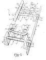
- FIG. 1 of the accompanying drawings there is shown diagrammatically in perspective, indicated generally as 1, equipment for the lateral transference of a pipe 2 in a rolling mill, more particularly for the transfer of a pipe 2 from one track with biconical rollers 3 to another track with biconical rollers 4 parallel to and alongside the first; for clarity in the drawing, the supports and the drives of the biconical rollers previously referred to are not shown since they are entirely conventional.
- Transference equipment comprises at least two transfer units T, identical and spaced apart in the direction in which the roller tracks 3 and 4 extend. These transfer units are supported and extend transversely to the roller tracks 3, 4 in question, and since they are identical, in the course of this description only one transfer unit will be described. All the elements which constitute the other transfer unit and which are identical to the elements which will be described for the first transfer unit will have the same reference numerals with the addition of the suffix a.
- Each transfer unit comprises a horizontal shaft 5 rotatably supported by a pair of supports 6, 7, positioned outside the roller tracks 3, 4 below which and perpendicularly to which the said shaft 5 extends.
- Two arms 8, 9, parallel to each other and of different length, are affixed cantilever-fashion to the said shaft 5, and extend radially relative to the same, from the same side and in positions thereon between the roller tracks 3, 4.
- the arm 8, nearer to the roller track 3, is of greater length than the arm 9.
- a pipe chute 10 comprising an intermediate rectilinear portion 11 and two end portions 12, 13, disposed in correspondence with the. roller tracks 3 and 4 respectively.
- the end portion 13 is curved away from the said shaft 5 in a sense such as to present its convex side towards the shaft 5.
- the said end portion 13 has its longitudinal axis coplanar with the longitudinal axes of the intermediate portion 11 and the shaft 5.
- the end portion 12 is rectilinear and is directed away from the said shaft 5 in the same direction as the end portion 13, but is skew with respect to the said shaft 5. More particularly, looking at the pipe chute 10 in a position in which the inter- meidate portion 11 and its end portion 13 are horizontal, the end portion 12 is inclined away from the said shaft 5, and downwards relative to the roller track 3.
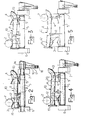
- the pipe chutes 10, 10a of the two (or more) transfer units T are designed to be moved angularly in synchronism about the axes of the respective shafts 5, 5a from a position in which they are completely below the roller tracks 3, 4 (non-operational position - Fig. 2), to a position in which they are completely above the said roller tracks (Fig. 5).
- the shafts 5, 5a have respective portions 14, 14a, outside, for example, the supports 7, 7a, connected mechanically, for example, by pairs of lugs 16, 17 and 16a and 17a, to a single connecting rod 18 to which a reciprocating movement is applied (Fig. 1).
- the end portions 12, 12a occupy successively higher positions above the roller track 3, becoming at the same time more inclined downwards and towards the adjacent, parallel roller track 4.
- the pipe 2, lifted up by the said end portions 12, 12a is safely prevented from rolling in an unwanted direction.
- the end portions 12, 12a previously referred to are fitted at their respective free ends with stops 19, 19a consisting, for example, of discs affixed coaxially to the heads of the end portions 12, 12a and which have an external diameter greater than the diameter of the chutes 10,10a.
- the pipe 2 can then roll as far as the curvilinear end portions 13, 13a where it is gently stopped.
- the pipe 2 is then lowered onto the roller track 4 by the angular movements of the pipe chutes 10, 10a about the axes of their respective shafts 5, 5a, in the opposite direction to that described previously, by displacing the connecting rod 18 in the opposite direction.
- chutes 10, 10a may with advantage be furnished, at the start of the curvilinear end portion 13, with projections 20 and 20a respectively so dimensioned as to facilitate a more rapid stopping of the pipe 2 as it rolls onto them.
Landscapes
- Engineering & Computer Science (AREA)
- Mechanical Engineering (AREA)
- Chutes (AREA)
- Rigid Pipes And Flexible Pipes (AREA)
- Branch Pipes, Bends, And The Like (AREA)
- Heat Treatment Of Articles (AREA)
- Manufacturing Of Tubular Articles Or Embedded Moulded Articles (AREA)
- Rollers For Roller Conveyors For Transfer (AREA)
Abstract
Description
- The present invention provides equipment for the lateral transference of pipes in, for example, a pipe rolling mill. More particularly this invention relates to equipment for transferring pipes laterally from one roller track to another roller track which extends parallel to and alongside the first.
- It is known that in rolling mills it is often necessary to move the pipes being worked between two or more parallel and adjacent pipe conveyor tracks, for example between one roller track extending from the delivery of one working stage to a roller track entering another working stage, with possible transfer and/or parking of the pipes upon intermediate roller tracks.
- In order to satisfy such a need, it is known to provide transfer devices of the type which consists fundamentally of a plurality of mechanical levers or arms extending transversely between the roller tracks in question and arranged for movement substantially in synchronism. The connection and reciprocal linkage of such levers or arms generally comprises a considerable number of articulated joints, control and drive mechanisms, mechanical transmissions, synchronising devices, slide guides, etc., all of which, as is well known, impart considerable complexity both to the structure and to the operation of transfer devices of this type.
- A first resultant disadvantage of such known transfer devices is the possibility of jamming, yielding etc. which may also require stopping of the production cycle of the rolling mill. This possibility is moreover increased by the fact that the transfer devices may operate in a hostile environment both by virtue of high temperature and also by virtue of the presence of dust, water, metal scales and the like.
- Taking into account the fact that in a pipe rolling mill production is continuous, it is clear that any stoppage, long or short, always causes a not inconsiderable economic loss.
- A further disadvantage lies in the fact that during lateral transference the pipes undergo impacts, which may be heavy, caused by the mechanical levers and arms of the transfer devices, with a consequent possibility of unacceptable distortions.
- The object of the present invention is that of providing equipment for the lateral transference of pipes in a pipe rolling-mill which has stuctural and functional characteristics such as to overcome the disadvantages, referred to above, with reference to the prior art.
- This object is resolved, according to the invention, by equipment for the lateral transference of pipes from one roller track to a adjacent parallel roller track, comprising at least two identical transfer units, spaced apart in the direction of the said roller tracks, characterised in that each of the said transfer units comprises
- - a horizontal shaft extending perpendicularly to the roller tracks and below them,
- - a pipe chute supported cantilever-fashion by said shaft and extending transversely to the said roller tracks, the said pipe chute having an intermediate rectilinear portion converging with the said horizontal shaft towards the roller track onto which a pipe is to be transferred, a curvilinear end portion with its convex part turned towards the shaft extending across the said roller track, and an end portion directed away from the said shaft and extending across the roller track from which the said pipe is to be transferred, and
- - means for moving the said pipe chute angularly about the axis of the said shaft between a lowered position in which it is completely below the said roller tracks and a raised position in which it is completely above them.
- Further characteristics and advantages of the invention will be clearer from the detailed description of one embodiment of transference equipment according to the said invention, given purely by way of non-limiting example, with reference to the accompanying drawings, in which:
- Figure 1 shows in perspective and diagrammatically equipment for the lateral transference of pipes;
- Figure 2 shows diagrammatically in the rest position and in side elevation one of the transfer units of equipment for the lateral transference of pipes;
- Figures 3, 4 and 5 show diagrammatically and in lateral view the said transfer unit of Figure 2 in successive operating positions for the lateral transference of a pipe.
- In Figure 1 of the accompanying drawings there is shown diagrammatically in perspective, indicated generally as 1, equipment for the lateral transference of a
pipe 2 in a rolling mill, more particularly for the transfer of apipe 2 from one track with biconical rollers 3 to another track withbiconical rollers 4 parallel to and alongside the first; for clarity in the drawing, the supports and the drives of the biconical rollers previously referred to are not shown since they are entirely conventional. - Transference equipment comprises at least two transfer units T, identical and spaced apart in the direction in which the roller tracks 3 and 4 extend. These transfer units are supported and extend transversely to the roller tracks 3, 4 in question, and since they are identical, in the course of this description only one transfer unit will be described. All the elements which constitute the other transfer unit and which are identical to the elements which will be described for the first transfer unit will have the same reference numerals with the addition of the suffix a.
- Each transfer unit comprises a
horizontal shaft 5 rotatably supported by a pair ofsupports 6, 7, positioned outside the roller tracks 3, 4 below which and perpendicularly to which the saidshaft 5 extends. - Two
arms shaft 5, and extend radially relative to the same, from the same side and in positions thereon between the roller tracks 3, 4. Thearm 8, nearer to the roller track 3, is of greater length than thearm 9. - To the free ends of the said
arms pipe chute 10, comprising an intermediate rectilinear portion 11 and twoend portions arms pipe chute 10 and theshaft 5 converge towards theroller track 4. - The
end portion 13 is curved away from the saidshaft 5 in a sense such as to present its convex side towards theshaft 5. The saidend portion 13 has its longitudinal axis coplanar with the longitudinal axes of the intermediate portion 11 and theshaft 5. - The
end portion 12 is rectilinear and is directed away from the saidshaft 5 in the same direction as theend portion 13, but is skew with respect to the saidshaft 5. More particularly, looking at thepipe chute 10 in a position in which the inter- meidate portion 11 and itsend portion 13 are horizontal, theend portion 12 is inclined away from the saidshaft 5, and downwards relative to the roller track 3. - The
pipe chutes respective shafts 5, 5a from a position in which they are completely below the roller tracks 3, 4 (non-operational position - Fig. 2), to a position in which they are completely above the said roller tracks (Fig. 5). - For this purpose the
shafts 5, 5a haverespective portions supports 7, 7a, connected mechanically, for example, by pairs oflugs rod 18 to which a reciprocating movement is applied (Fig. 1). - In order to transfer a
pipe 2 from the roller track 3 to the adjacentparallel roller track 4, the following sequence of operations is effected. - In the initial state the
pipe chutes rod 18, the saidpipe chutes respective shafts 5, 5a until theend portions pipe 2. It must be pointed out that when this contact occurs theend portions pipe 2, and, hence to the roller track 3. - Continuing with the aforesaid angular movements, the
end portions parallel roller track 4. In this manner thepipe 2, lifted up by the saidend portions pipe 2 rolling to the outside of the roller track 3 in question, theend portions stops end portions chutes - It must be pointed out (Figs 4 and 5) that as soon as the
end portions pipe 2 out of the biconical rollers 3, the remaining portions, that is, theintermediate portions 11, 11a andcurvilinear end portions 13, 13a will be completely above theroller track 4, theintermediate portions 11, 11a being inclined downwards and towards the latter roller track. - The
pipe 2 can then roll as far as thecurvilinear end portions 13, 13a where it is gently stopped. Thepipe 2 is then lowered onto theroller track 4 by the angular movements of thepipe chutes respective shafts 5, 5a, in the opposite direction to that described previously, by displacing the connectingrod 18 in the opposite direction. - It must be pointed out that the said
chutes curvilinear end portion 13, withprojections pipe 2 as it rolls onto them.
Claims (3)
Priority Applications (1)
| Application Number | Priority Date | Filing Date | Title |
|---|---|---|---|
| AT84830365T ATE30859T1 (en) | 1984-01-13 | 1984-12-31 | LATERAL CONVEYOR FOR PIPES. |
Applications Claiming Priority (2)
| Application Number | Priority Date | Filing Date | Title |
|---|---|---|---|
| IT1915584 | 1984-01-13 | ||
| IT19155/84A IT1173027B (en) | 1984-01-13 | 1984-01-13 | EQUIPMENT FOR LATERAL TRANSFER OF PIPES IN A PIPE LAMINATION PLANT |
Publications (2)
| Publication Number | Publication Date |
|---|---|
| EP0161381A1 EP0161381A1 (en) | 1985-11-21 |
| EP0161381B1 true EP0161381B1 (en) | 1987-11-19 |
Family
ID=11155341
Family Applications (1)
| Application Number | Title | Priority Date | Filing Date |
|---|---|---|---|
| EP84830365A Expired EP0161381B1 (en) | 1984-01-13 | 1984-12-31 | Equipment for the lateral transference of pipes |
Country Status (6)
| Country | Link |
|---|---|
| US (1) | US4593807A (en) |
| EP (1) | EP0161381B1 (en) |
| AT (1) | ATE30859T1 (en) |
| CA (1) | CA1221115A (en) |
| DE (1) | DE3467517D1 (en) |
| IT (1) | IT1173027B (en) |
Families Citing this family (9)
| Publication number | Priority date | Publication date | Assignee | Title |
|---|---|---|---|---|
| GB8804499D0 (en) * | 1988-02-26 | 1988-03-30 | British Nuclear Fuels Plc | Apparatus for handling elongate articles |
| US5257716A (en) * | 1992-09-10 | 1993-11-02 | Armco Inc. | Pipe manufacturing method and apparatus |
| US5413207A (en) * | 1993-06-08 | 1995-05-09 | Pong; David T. | Method and apparatus for delivering rolled rod to a cooling bed |
| US7198452B2 (en) * | 2004-04-08 | 2007-04-03 | Ocenco, Inc. | Bar stock loading table and apparatus |
| US7299912B2 (en) * | 2005-02-18 | 2007-11-27 | Midwest Pipe Coating, Inc. | Conveyor for bar or pipe |
| US7815032B2 (en) * | 2007-07-02 | 2010-10-19 | Control Flow Inc. | Pipe roller assembly |
| US11267027B2 (en) * | 2019-12-10 | 2022-03-08 | Granco Clark, Inc. | Nonferrous extrusion handling systems and processes |
| DE102020205250B4 (en) * | 2020-04-24 | 2021-11-11 | Kocks Technik Gmbh & Co Kg | Guide device for long products |
| CN117066284A (en) * | 2023-08-24 | 2023-11-17 | 宁波东重机械有限公司 | A continuous cold rolling pipe machine |
Family Cites Families (8)
| Publication number | Priority date | Publication date | Assignee | Title |
|---|---|---|---|---|
| US701024A (en) * | 1901-11-04 | 1902-05-27 | Morgan Construction Co | Conveyer for metal rods or bars. |
| US1021582A (en) * | 1908-10-30 | 1912-03-26 | American Steel & Wire Co | Apparatus for handling metal bars. |
| GB507369A (en) * | 1937-05-03 | 1939-06-14 | Mannesmann Ag | Tube cooling bed |
| DE893484C (en) * | 1952-02-28 | 1953-10-15 | Westdeutsche Mannesmannroehren | Device for gentle storage of pipes or the like. |
| US3129805A (en) * | 1961-12-14 | 1964-04-21 | Amsted Ind Inc | Take-off conveyor |
| DE1602107A1 (en) * | 1967-04-24 | 1970-07-23 | Mannesmann Meer Ag | Device for the time-independent charging of multiple cold pilger mills with tube blanks |
| US3812951A (en) * | 1972-05-16 | 1974-05-28 | Weyerhaeuser Co | Log handling apparatus |
| JPS521858A (en) * | 1975-06-24 | 1977-01-08 | Hitachi Metals Ltd | Steel pipe transfer apparatus |
-
1984
- 1984-01-13 IT IT19155/84A patent/IT1173027B/en active
- 1984-12-31 AT AT84830365T patent/ATE30859T1/en not_active IP Right Cessation
- 1984-12-31 DE DE8484830365T patent/DE3467517D1/en not_active Expired
- 1984-12-31 EP EP84830365A patent/EP0161381B1/en not_active Expired
-
1985
- 1985-01-07 CA CA000471616A patent/CA1221115A/en not_active Expired
- 1985-01-11 US US06/690,530 patent/US4593807A/en not_active Expired - Fee Related
Also Published As
| Publication number | Publication date |
|---|---|
| ATE30859T1 (en) | 1987-12-15 |
| DE3467517D1 (en) | 1987-12-23 |
| US4593807A (en) | 1986-06-10 |
| CA1221115A (en) | 1987-04-28 |
| EP0161381A1 (en) | 1985-11-21 |
| IT1173027B (en) | 1987-06-18 |
| IT8419155A0 (en) | 1984-01-13 |
Similar Documents
| Publication | Publication Date | Title |
|---|---|---|
| US4593807A (en) | Equipment for the lateral transference of pipes | |
| GB1603660A (en) | Apparatus for handling a multiplicity of articles in a convergent path and side guide means therefor | |
| US4378741A (en) | Interfaced conveyor systems and driverless vehicle for use therein | |
| US3323632A (en) | Apparatus for setting up and shifting workpieces | |
| CN1170962C (en) | Transverse conveyor for electrodes | |
| CN218706772U (en) | Reinforcing bar conveyor for construction | |
| US4624637A (en) | Rolling pipe centering apparatus | |
| US1998806A (en) | Transfer device | |
| US3236396A (en) | Workpiece manipulator | |
| EP0964757A1 (en) | Apparatus for introducing tubes or rod-shaped bodies, with a rotational/translational movement, into machines for processing them | |
| US3675789A (en) | Ingot manipulator for a rolling mill | |
| SU1146113A1 (en) | Slab pusher | |
| RU2129928C1 (en) | Apparatus for moving rolled stock | |
| CN113371260A (en) | Product correcting device of packaging equipment | |
| US4498324A (en) | Restrained mandrel mill inlet table | |
| SU712164A1 (en) | Straightening arrangement | |
| SU841755A1 (en) | Apparatus for charging front tables of ball rolling mills | |
| WO1992006907A1 (en) | Glass sheet transferring device | |
| US3741408A (en) | Transfer apparatus | |
| SU764910A1 (en) | Device for transfering articles between working stations | |
| CN216996109U (en) | Automatic conveying device for titanium bars | |
| SU1235591A1 (en) | Power-operated line for transferring and accumulating coils | |
| SU899186A1 (en) | Elongated rolled stock handler | |
| US1786575A (en) | Conveyer table | |
| SU1722640A1 (en) | Apparatus for distributing tubes from sloped skid to parallel roller tables of mandrel removers |
Legal Events
| Date | Code | Title | Description |
|---|---|---|---|
| PUAI | Public reference made under article 153(3) epc to a published international application that has entered the european phase |
Free format text: ORIGINAL CODE: 0009012 |
|
| AK | Designated contracting states |
Designated state(s): AT BE CH DE FR GB LI LU NL SE |
|
| 17P | Request for examination filed |
Effective date: 19851218 |
|
| 17Q | First examination report despatched |
Effective date: 19870213 |
|
| GRAA | (expected) grant |
Free format text: ORIGINAL CODE: 0009210 |
|
| AK | Designated contracting states |
Kind code of ref document: B1 Designated state(s): AT BE CH DE FR GB LI LU NL SE |
|
| PG25 | Lapsed in a contracting state [announced via postgrant information from national office to epo] |
Ref country code: NL Effective date: 19871119 Ref country code: LI Effective date: 19871119 Ref country code: CH Effective date: 19871119 Ref country code: BE Effective date: 19871119 Ref country code: AT Effective date: 19871119 |
|
| REF | Corresponds to: |
Ref document number: 30859 Country of ref document: AT Date of ref document: 19871215 Kind code of ref document: T |
|
| PG25 | Lapsed in a contracting state [announced via postgrant information from national office to epo] |
Ref country code: SE Effective date: 19871130 |
|
| REF | Corresponds to: |
Ref document number: 3467517 Country of ref document: DE Date of ref document: 19871223 |
|
| PG25 | Lapsed in a contracting state [announced via postgrant information from national office to epo] |
Ref country code: LU Free format text: LAPSE BECAUSE OF NON-PAYMENT OF DUE FEES Effective date: 19871231 |
|
| REG | Reference to a national code |
Ref country code: CH Ref legal event code: PL |
|
| NLV1 | Nl: lapsed or annulled due to failure to fulfill the requirements of art. 29p and 29m of the patents act | ||
| ET | Fr: translation filed | ||
| PLBI | Opposition filed |
Free format text: ORIGINAL CODE: 0009260 |
|
| 26 | Opposition filed |
Opponent name: HOESCH AG Effective date: 19880816 |
|
| PLBN | Opposition rejected |
Free format text: ORIGINAL CODE: 0009273 |
|
| STAA | Information on the status of an ep patent application or granted ep patent |
Free format text: STATUS: OPPOSITION REJECTED |
|
| 27O | Opposition rejected |
Effective date: 19891127 |
|
| PGFP | Annual fee paid to national office [announced via postgrant information from national office to epo] |
Ref country code: GB Payment date: 19911114 Year of fee payment: 8 |
|
| PGFP | Annual fee paid to national office [announced via postgrant information from national office to epo] |
Ref country code: DE Payment date: 19911121 Year of fee payment: 8 |
|
| PGFP | Annual fee paid to national office [announced via postgrant information from national office to epo] |
Ref country code: FR Payment date: 19911230 Year of fee payment: 8 |
|
| REG | Reference to a national code |
Ref country code: GB Ref legal event code: 732 |
|
| REG | Reference to a national code |
Ref country code: FR Ref legal event code: TP |
|
| PG25 | Lapsed in a contracting state [announced via postgrant information from national office to epo] |
Ref country code: GB Effective date: 19921231 |
|
| GBPC | Gb: european patent ceased through non-payment of renewal fee |
Effective date: 19921231 |
|
| PG25 | Lapsed in a contracting state [announced via postgrant information from national office to epo] |
Ref country code: FR Effective date: 19930831 |
|
| PG25 | Lapsed in a contracting state [announced via postgrant information from national office to epo] |
Ref country code: DE Effective date: 19930901 |
|
| REG | Reference to a national code |
Ref country code: FR Ref legal event code: ST |