EP0161087B1 - A windshield defroster assembly - Google Patents
A windshield defroster assembly Download PDFInfo
- Publication number
- EP0161087B1 EP0161087B1 EP19850302839 EP85302839A EP0161087B1 EP 0161087 B1 EP0161087 B1 EP 0161087B1 EP 19850302839 EP19850302839 EP 19850302839 EP 85302839 A EP85302839 A EP 85302839A EP 0161087 B1 EP0161087 B1 EP 0161087B1
- Authority
- EP
- European Patent Office
- Prior art keywords
- screen
- duct
- edge
- windshield
- projection
- Prior art date
- Legal status (The legal status is an assumption and is not a legal conclusion. Google has not performed a legal analysis and makes no representation as to the accuracy of the status listed.)
- Expired
Links
Images




Classifications
-
- B—PERFORMING OPERATIONS; TRANSPORTING
- B60—VEHICLES IN GENERAL
- B60H—ARRANGEMENTS OF HEATING, COOLING, VENTILATING OR OTHER AIR-TREATING DEVICES SPECIALLY ADAPTED FOR PASSENGER OR GOODS SPACES OF VEHICLES
- B60H1/00—Heating, cooling or ventilating devices
- B60H1/34—Nozzles; Air-diffusers
- B60H1/3407—Nozzles; Air-diffusers providing an air stream in a fixed direction, e.g. using a grid or porous panel
-
- B—PERFORMING OPERATIONS; TRANSPORTING
- B60—VEHICLES IN GENERAL
- B60H—ARRANGEMENTS OF HEATING, COOLING, VENTILATING OR OTHER AIR-TREATING DEVICES SPECIALLY ADAPTED FOR PASSENGER OR GOODS SPACES OF VEHICLES
- B60H1/00—Heating, cooling or ventilating devices
- B60H1/34—Nozzles; Air-diffusers
- B60H1/3414—Nozzles; Air-diffusers with means for adjusting the air stream direction
-
- B—PERFORMING OPERATIONS; TRANSPORTING
- B60—VEHICLES IN GENERAL
- B60S—SERVICING, CLEANING, REPAIRING, SUPPORTING, LIFTING, OR MANOEUVRING OF VEHICLES, NOT OTHERWISE PROVIDED FOR
- B60S1/00—Cleaning of vehicles
- B60S1/02—Cleaning windscreens, windows or optical devices
- B60S1/54—Cleaning windscreens, windows or optical devices using gas, e.g. hot air
-
- B—PERFORMING OPERATIONS; TRANSPORTING
- B60—VEHICLES IN GENERAL
- B60H—ARRANGEMENTS OF HEATING, COOLING, VENTILATING OR OTHER AIR-TREATING DEVICES SPECIALLY ADAPTED FOR PASSENGER OR GOODS SPACES OF VEHICLES
- B60H1/00—Heating, cooling or ventilating devices
- B60H1/34—Nozzles; Air-diffusers
- B60H2001/3492—Manufacturing; Assembling
Definitions
- the present invention relates to a windshield defroster for a vehicle, and more particularly to improvements in a screen for preventing an object from dropping into a defroster duct through a defroster outlet formed in a top surface of a dashboard of the vehicle.
- European Patent Application No. 85302840.5 (filed on April 23rd, 1985, under the same priority dates of May 3rd and July 12th, 1984 as the present application and published under EP-A-0161839) which is entitled "A Windshield Defroster Assembly”, discloses a windshield defroster having a plate or rudder secured to a defroster duct to control the flow of heated air.
- the plate or rudder is also secured to a screen which is attached to the defroster duct.
- Figs. 13 and 14 show a prior art approach disclosed in Japanese Utility Model Applications Laid-open No. Showa JP-U-51/82236 which represents the preamble of Claim 1.
- a windshield defroster includes a duct 30 and a screen 50 having a plurality of openings 502 and a plurality of bars 501.
- the screen 50 is disposed on one end of the duct 30, and the screen 50 is integrally and rigidly formed with duct 30.
- the screen 50 is separted from the defroster duct 30. Accordingly, the screen 50 which prevents an object from dropping into the duct 30, must be fixed to the duct 30 prior to the windshield defroster being installed into the dashboard of the vehicle. Further, screen 50 covers the entire outlet area of the duct 30, so that screen 50 must be large and heavy. Therefore, even if it is possible to form the defroster duct 30 having the integral, rigid and entirely covered screen 50, this prior art approach increases the material and labour requirements during installation of the duct 30 under the dashboard 20.
- Figs. 15 through Fig. 20 show other prior art approaches. Windshield defrosters shown in Figs. 15,16 and 18 do not utilize a screen for preventing an object from dropping into the defroster duct 30.
- the windshield defroster shown in Fig. 17 includes a plurality of openings 502 and a plurality of bars 501 provided in the top surface 201 of dashboard 20. While the windshield defroster shown in Fig. 17 can prevent an object from dropping into the defroster duct 30, it is very difficult to align the openings 502 and bars 501 within the top surface 201 of dashboard 20 with the defroster outlet 70 in the dashboard 20.
- the windshield defroster shown in Fig. 19 has a separate screen 50 which is placed within the defroster outlet 70 of the dashboard 20.
- the screen 50 includes a plurality of bars 501 and a plurality of openings 502.
- the windshield defroster shown in Fig. 20 has a separate net-type screen 50. Both of these windshield defrosters include a screen 50 which is separated from the dashboard 20 and duct 30, so that each windshield defroster consists of many components and it is therefore necessary for the installer to assemble many components to the dashboard 20, before the duct 30 is installed under the dashboard 20.
- the present invention has been developed to overcome the disadvantages described above.
- One object of the present invention is to provide a windshield defroster which prevent an object from dropping into a duct through a defroster outlet.
- Another object is to provide a windshield defroster duct which requires very little material and therefore lightens the weight of the vehicle.
- Another object is to provide of a windshield defroster in which it is easy to install a screen in the windshield defroster duct without spening much time or labour.
- the invention provides a windshield defroster having the characterizing features of Claim 1.
- Each screen has a free edge or a second edge which is positioned within the outlet which is defined within the upper peripheral edge of the duct. Since most of the outlet of the duct is not covered by the screen, the duct does not require a lot of excess materials and therefore the duct is lighter thereby reducing the weight of the vehicle.
- the duct may have a first projection which extends horizontally from the upper peripheral edge, and the screen has a lower surface which is in contact with the horizontal surface of the first projection of the duct.
- the hinge described above, connects a front edge of the first projection to one edge of the screen.
- the screen is supported by the first projection of the duct and the hinge and the screen extend horizontally without any additional support for the free edge of the screen.
- the screen may include a protrusion on the lower surface thereof, and the upper peripheral edge of the duct has a recess. A pair of blocks are raised from the bottom surface of the recess. The protrusion is inserted into the recess and the protrusion is therefore in frictional contact with the pair of blocks, so that the screen cannot rotate about the hinge, and the screen does not make any noise on the upper peripheral edge of .the duct or the bottom surface of the dashboard. Furthermore, it is easy to install the duct under the dashboard, because it is not necessary for the installer to concern himself with the screen.
- each screen would have an edge which is connected to the upper peripheral edge of the duct by a hinge.
- a dashboard 20 is positioned at the frontward portion of a passenger compartment of a vehicle and the dashboard 20 extends in the lateral direction between the sides of the vehicles.
- a top surface 201 of the dashboard 20 is located under a windshield 10, and the top surface 201 of the dashboard 20 extends horizontally.
- the top surface 201 includes a plurality of defroster outlets 70 and each defroster outlet 70 has a plurality of bars 501 therein. These bars 501 prevent an object from dropping into the defroster outlet 70, and these bars 501 are fixed on a screen 50.
- the screen 50 includes an opening 502 under the bars 501, and the bars 501 cross over the opening 502.
- the bars 501 extend in a direction perpendicular to the greatest extent of the dashboard 20, and the bars 501 separate the opening 502 into various sections.
- the dashboard 20 includes an instrument panel 209 on a rear portion thereof, and a first duct 30 is positioned under the dashboard 20.
- a second duct 305, a blower 306 and a heater 307 are arranged under the first duct 30.
- a defroster outlet 70 is placed in the top surface 201 of dasboard 20, in the front portion of the dashboard 20.
- the dashboard 20 has a recess 203 and a hook 204 on the bottom surface 202 thereof.
- the recess 203 is located on the central portion of the bottom surface 202 of the dashboard 20 toward the rear of the vehicle, and the recess 203 extends in the lateral direction of the vehicle. Further, the cavity of the recess 203' faces the front of the vehicle.
- the hook 204 is located in the vicinity of the front edge of the bottom surface 202 of the dashboard 20, and the hook 204 extends in the lateral direction of the vehicle. Furthermore, an end of the hook 204 extends toward the rear of the vehicle, and the defroster outlet 70 is disposed between the recess 203 and the hook 204.
- the first duct 30 has an upper edge which forms a first projection 301 and a second projection 302.
- the first dashboard 301 of the first duct 30 is mounted on the hook 204 of the dashboard 20, and the first projection 301 extends horizontally toward the front of the vehicle.
- the second projection 302 of the first duct 30 is inserted into the recess 203 of the dashboard 20, and the second projection 302 extends horizontally toward the rear of the vehicle. It is easy to install the first duct 30 on the bottom surface 202 of the dashboard 20, because the first projection 301 of the first duct 30 can be mounted on the hook 204 of the dashboard 20, and then the second projection 302 of the first duct 30 can be inserted into the recess 203 of the dashboard 20.
- the second projection 302 can be pushed toward the front of the vehicle, since the duct 30 is somewhat elastic, so that the second projection 302 can be inserted into the recess 203.
- a seal member 304 is positioned beween a lower edge 303 of the first duct 30 and a top edge of a second duct 305.
- This second duct 305 communicates with the heater 307.
- the heater 307 is placed under the dashboard 20, and the heater 307 heats the air.
- the blower 306 is positioned in the vicinity of the heater 307, and the blower 306 distribute the warm air to the defroster outlet 70 through the second duct 305 and the first duct 30.
- the first duct 30 includes a screen 50 on the first projection 301 of the first duct 30.
- a front or first edge of the screen 50 is connected to a front edge of the first projection 301 of the first duct 30 by a hinge 40, and the hinge 40 is integrated with the first duct 30 and the screen 50. Therefore, the screen 50 can rotate about the hinge 40 on the first projection 301 of the first duct 30.
- the screen 50 has a lower surface which is in contact with the upper surface of the first projection 301 of the duct 30. Accordingly, the screen 50 extends horizontally from the upper peripheral edge of the first duct 30, when the screen 50 is bent back on the first projection 301 of the duct 30.
- the screen 50 is supported horizontally under the bottom surface 202 of the dashboard 20 without any support for the other edge or second edge of the screen 50 which is parallel to the front or first edge of the screen 50.
- the opening 502 of the screen 50 is congruent with the defroster outlet 70, so that the warm air is distributed to the defroster outlet 70 through the opening 502 of the screen 50.
- Both ends of the bar 501 are fixed on an inner peripheral edge of the opening 502 of the screen 50, and a plurality of the bars 501 are located in a parallel relationship to each other. An intermediate portion of each bar 501 is placed in the defroster outlet 70.
- the screen 50 can prevent an object from dropping into the first duct 30 through the defroster outlet 70.
- Figs. 4 through 8 show a windshield defroster of a second embodiment. While most of the components in the second embodiment are the same as those previously described above for the first embodiment, the second embodiment has several differences.
- a first duct 30 includes a plurality of screens 50 on a first projection 301 of the first duct 30, and as shown in Fig. 5, a first edge 503 of each screen 50 is connected to a front edge of the first projection 301 by a hinge 40.
- the hinge 40 is integrated with the first duct 30 and the screen 50, and the screen 50 includes an opening 502 which is separated by a plurality of bars 501.
- the screen 50 includes a reinforcement 80 at the lateral central portion of the screen 50.
- the reinforcement 80 extends from the first edge 503 to the second edge 504.
- the reinforcement 80 is fixed on the lower surface of the screen 50.
- the reinforcement 80 extends downwardly and has a slanted edge 801 in the vicinity of the first edge 503 of the screen 50.
- the slanted edge 801 slants to the left as shown in Fig. 7.
- the first duct 30 includes a first recess 802 in the upper peripheral edge thereof.
- a slanted bottom 803 is formed in the first recess 802, and the slanted bottom 803 slants to the left as shown in Fig. 7.
- the first recess 802 is disposed in the vicinty of the reinforcement 80, so that the slanted edge 801 of the reinforcement 80 is in contact with the slanted bottom 803 of the first recess 802, when the screen 50 is positioned back on the first projection 301 of the first duct 30.
- the screen 50 is supported horizontally by the slanted edge 801 of the reinforcement 80 and the slanted bottom 803 of the first recess 802 without any support for the second edge 504 of the screen 50.
- the second edge 504 may be in contact with the bottom surface 202 of the dashboard 20.
- the screen 50 can prevent an object from dropping into the first duct 30 through the defroster outlet 70, even if the object is heavy.
- the screen 50 includes a protrusion 60 on the lower surface thereof, and the protrusion 60 is formed in the shape of the letter 'U'.
- the protrusion 60 has a bottom end 602 and has two free ends 603. Furthermore, the protrusion 60 includes contact surfaces 601 on both sides in the vicinity of the two free ends 603 of protrusion 60.
- the first duct 30 includes a second recess 90 in the upper peripheral edge thereof, and a horizontal bottom 902 is formed in the second recess 90.
- Two blocks 901 are raised within the second recess 90, and each block 901 has a contact side.
- the contact side 904 of block 901 faces the contact side 905 of the other block 901, and as shown in Fig. 8, both contact surfaces 601 of protrusion 60 are in frictional contact with the contact sides 904 and 905 of the respective blocks 901.
- the screen 50 is mounted securely on the first projection 301 of the first duct 30 by the protrusion 60 of the screen 50 and the second recess 90 of the first duct 30, and the screen 50 will not rotate about the hinge 40 since the protrusion 60 of the screen 50 has been inserted into the second recess 90. Therefore, it is not necessary for the defroster installer to concern himself with the screen 50 once the screen 50 is positioned back onto the first projection 301 of the first duct 30, and the protrusion 60 is inserted into the second recess 90.
- the bottom end 602 of the protrusion 60 is in contact with the horizontal bottom 902 of the second recess 90. Therefore, the bottom end 602 of the protrusion 60 and the horizontal bottom 902 of the second recess 90 prevent the screen 50 from bending past an imaginary horizontal plane of the vehicle.
- Fig. 9 shows a windshield defroster of a third embodiment. While most of the components in the third embodiment are the same as those previously described for the second embodiment, the third embodiment has several differences.
- a dashboard 20 includes a first hook 208, a second hook 204, and a third hook 206 on the bottom surface 202 of dashboard 20.
- the first hook 208 is formed on the central portion of the bottom surface 202, toward the rear of the vehicle, and the first hook 208 extends in the lateral direction of a vehicle. Also, an end of the first hook 208 extends toward the front of the vehicle.
- the second hook 204 is formed in the vicinity of the front edge of the bottom surface 202 of the dashboard 20, and the second hook 204 extends in the lateral direction of the vehicle. An end of the second hook 204 extends toward the rear of the vehicle.
- the third hook 206 is formed between the first hook 208 and the second hook 204, and the third hook 206 extends in the lateral direction of the vehicle. Also, an end of the third hook extends toward the front of the vehicle.
- the dashboard 20 has a defroster outlet 70, and a screen 50 is placed under the defroster outlet 70.
- An first edge 503 of the screen 50 is connected to the front edge of the first projection 301 of the first duct 30, and the first edge 503 of the screen 50 and the front edge of the first projection 301 are mounted within the second hook 204.
- the second edge 504 of the screen 50 is mounted within the third hook 206, and a second projection 302 of the first duct 30 is mounted on the first hook 208.
- the first duct 30 and the screen 50 are mounted securely on the bottom surface 202 of the dashboard 20, so that the screen 50 can prevent an object from dropping into the first duct 30 through the defroster outlet 70, even if the object is heavy.
- Figs. 10 through 12 show a windshield defroster of a fourth embodiment. While most of components in the fourth embodiment are the same as those previously described above for the second embodiment, the fourth embodiment has several differences.
- a screen 50 has a pair of projections 660 on the lower surface thereof, and the projections 660 are wedge-shaped.
- a first duct 30 includes a pair of holes 990 and a pair of props 991 on the upper peripheral edge of the first duct 30.
- each of the pair of the projections 660 is inserted into one of the holes 990, when the screen 50 is bent back onto the first projection 301 of the first duct 30.
- the lower surface of the screen 50 is supported by the prop 991, and the projection 660 of the screen 50 engages the hole 990 of the first projection 301 of the first duct 30.
- the screen 50 is fixed securely on the first projection 301 of the first duct 30. Therefore, the screen 50 can prevent an object form dropping into the first duct 30 through the defroster outlet 70, even if the object is heavy.
- the windshield defroster of the present invention can prevent an object from dropping into a duct through a defroster outlet, and this advantage can be obtained using less time and labor during the installation of the duct underneath the dashboard.
Landscapes
- Engineering & Computer Science (AREA)
- Mechanical Engineering (AREA)
- Physics & Mathematics (AREA)
- Thermal Sciences (AREA)
- Air-Conditioning For Vehicles (AREA)
Description
- The present invention relates to a windshield defroster for a vehicle, and more particularly to improvements in a screen for preventing an object from dropping into a defroster duct through a defroster outlet formed in a top surface of a dashboard of the vehicle.
- European Patent Application No. 85302840.5 (filed on April 23rd, 1985, under the same priority dates of May 3rd and July 12th, 1984 as the present application and published under EP-A-0161839) which is entitled "A Windshield Defroster Assembly", discloses a windshield defroster having a plate or rudder secured to a defroster duct to control the flow of heated air. In another embodiment the plate or rudder is also secured to a screen which is attached to the defroster duct.
- Figs. 13 and 14 show a prior art approach disclosed in Japanese Utility Model Applications Laid-open No. Showa JP-U-51/82236 which represents the preamble of
Claim 1. As illustrated in Figs. 13 and 14, a windshield defroster includes aduct 30 and ascreen 50 having a plurality ofopenings 502 and a plurality ofbars 501. Thescreen 50 is disposed on one end of theduct 30, and thescreen 50 is integrally and rigidly formed withduct 30. - However, in fact, it is very difficult to form the
defroster duct 30 which has the integral andrigid screen 50. Therefore, generally, thescreen 50 is separted from thedefroster duct 30. Accordingly, thescreen 50 which prevents an object from dropping into theduct 30, must be fixed to theduct 30 prior to the windshield defroster being installed into the dashboard of the vehicle. Further,screen 50 covers the entire outlet area of theduct 30, so thatscreen 50 must be large and heavy. Therefore, even if it is possible to form thedefroster duct 30 having the integral, rigid and entirely coveredscreen 50, this prior art approach increases the material and labour requirements during installation of theduct 30 under thedashboard 20. - Figs. 15 through Fig. 20 show other prior art approaches. Windshield defrosters shown in Figs. 15,16 and 18 do not utilize a screen for preventing an object from dropping into the
defroster duct 30. - The windshield defroster shown in Fig. 17 includes a plurality of
openings 502 and a plurality ofbars 501 provided in thetop surface 201 ofdashboard 20. While the windshield defroster shown in Fig. 17 can prevent an object from dropping into thedefroster duct 30, it is very difficult to align theopenings 502 andbars 501 within thetop surface 201 ofdashboard 20 with thedefroster outlet 70 in thedashboard 20. - The windshield defroster shown in Fig. 19 has a
separate screen 50 which is placed within thedefroster outlet 70 of thedashboard 20. Thescreen 50 includes a plurality ofbars 501 and a plurality ofopenings 502. Furthermore, the windshield defroster shown in Fig. 20 has a separate net-type screen 50. Both of these windshield defrosters include ascreen 50 which is separated from thedashboard 20 andduct 30, so that each windshield defroster consists of many components and it is therefore necessary for the installer to assemble many components to thedashboard 20, before theduct 30 is installed under thedashboard 20. - The present invention has been developed to overcome the disadvantages described above. One object of the present invention is to provide a windshield defroster which prevent an object from dropping into a duct through a defroster outlet. Another object is to provide a windshield defroster duct which requires very little material and therefore lightens the weight of the vehicle.
- Another object is to provide of a windshield defroster in which it is easy to install a screen in the windshield defroster duct without spening much time or labour.
- In order to accomplish the above-described objects, the invention provides a windshield defroster having the characterizing features of
Claim 1. - Each screen has a free edge or a second edge which is positioned within the outlet which is defined within the upper peripheral edge of the duct. Since most of the outlet of the duct is not covered by the screen, the duct does not require a lot of excess materials and therefore the duct is lighter thereby reducing the weight of the vehicle.
- The duct may have a first projection which extends horizontally from the upper peripheral edge, and the screen has a lower surface which is in contact with the horizontal surface of the first projection of the duct. Furthermore, the hinge, described above, connects a front edge of the first projection to one edge of the screen. The screen is supported by the first projection of the duct and the hinge and the screen extend horizontally without any additional support for the free edge of the screen. Thus, it is not neccessary for the installer to fix the screen on the upper peripheral edge of the duct, and it is only necessary for the installer to bend back the screen on the upper peripheral edge of the duct along the hinge, before the duct is installed under the dashboard.
- The screen may include a protrusion on the lower surface thereof, and the upper peripheral edge of the duct has a recess. A pair of blocks are raised from the bottom surface of the recess. The protrusion is inserted into the recess and the protrusion is therefore in frictional contact with the pair of blocks, so that the screen cannot rotate about the hinge, and the screen does not make any noise on the upper peripheral edge of .the duct or the bottom surface of the dashboard. Furthermore, it is easy to install the duct under the dashboard, because it is not necessary for the installer to concern himself with the screen.
- It is noted that instead of a signal screen, a plurality of screens could be integrated into the duct. In this case, each screen would have an edge which is connected to the upper peripheral edge of the duct by a hinge.
- Also, it is clear that a plurality of defroster outlets, with their respective defroster ducts and screens, could be positioned across the dashboard of a vehicle.
- Additional objects and novel features of this invention will become more apparent from the description which follows taken in conjunction with the accompanying drawings, wherein like reference numerals denote like elements, and in which:
- Fig. 1 is a perspective view showing a windshield defroster according to the present invention;
- Fig. 2 is an enlarged cross-sectional view of the windshield defroster of a first embodiment taken along the line 11-11 in Fig. 1;
- Fig. 3 is an enlarged partial perspective view showing the arrangement of components around the defroster outlet of the first embodiment;
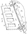
- Fig. 4 is a partial perspective view showing a duct of a windshield defroster of a second embodiment;
- Fig. 5 is an enlarged partial perspective view showing a screen of the duct shown in Fig. 4;
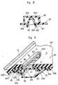
- Fig. 6 is an enlarged partial cross-sectional view of the windshield defroster taken along the line VI-VI in Fig. 5, wherein the screen is bent back on the upper peripheral edge of a duct;
- Fig. 7 is an enlarged partial cross-sectional view of the windshield defroster taken along the line VII-VII in Fig 5, wherein the screen is bent back on the upper peripheral edge of the duct;
- Fig. 8 is an enlarged partial cross-sectional view of the windshield defroster taken along the line VIII-VIII in Fig. 6;
- Fig. 9 is an enlarged partial cross-sectional view of a windshield defroster of a third embodiment taken along the line VI-VI in Fig. 5, wherein the screen is bent back on the upper peripheral edge of the duct;
- Fig. 10 is an enlarged partial perspective view showing a screen of a duct of a windshield defroster of a fourth embodiment;
- - Fig. 11 is an enlarged partial cross-sectional view of the windshield defroster taken along the line XI-XI in Fig. 10, wherein the screen is bent back on the upper peripheral edge of the duct;
- Fig. 12 is an enlarged partial cross-sectional view of the windshield defroster taken along the line XII-XII in Fig. 11;
- Fig. 13 is an enlarged perspective view showing the arrangement of components disposed around the screen disclosed in Japanese Utility Model Application Laid-open No. Showa 51-82236;
- Fig. 14 is an enlarged perspective view showing the arrangement of components around another screen disclosed in Japanese Utility Model Application Laid-open Showa 51-82236;
- Fig. 15 is a cross-sectional view showing components of a third conventional windshield defroster;
- Fig. 16 is a cross-sectional view showing components of a fourth conventional windshield defroster;
- Fig. 17 is a cross-sectional view showing components of a fifth conventional windshield defroster;
- Fig. 18 is a cross-sectional view showing components of a sixth conventional windshield defroster;
- Fig. 19 is a cross-sectional view showing components of a seventh conventional windshield defroster; and
- Fig. 20 is a cross-sectional view showing components of an eighth conventional windshield defroster.
- Referring to Fig. 1, a
dashboard 20 is positioned at the frontward portion of a passenger compartment of a vehicle and thedashboard 20 extends in the lateral direction between the sides of the vehicles. Atop surface 201 of thedashboard 20 is located under awindshield 10, and thetop surface 201 of thedashboard 20 extends horizontally. Thetop surface 201 includes a plurality ofdefroster outlets 70 and eachdefroster outlet 70 has a plurality ofbars 501 therein. Thesebars 501 prevent an object from dropping into thedefroster outlet 70, and thesebars 501 are fixed on ascreen 50. Thescreen 50 includes anopening 502 under thebars 501, and thebars 501 cross over theopening 502. Thebars 501 extend in a direction perpendicular to the greatest extent of thedashboard 20, and thebars 501 separate theopening 502 into various sections. Thedashboard 20 includes aninstrument panel 209 on a rear portion thereof, and afirst duct 30 is positioned under thedashboard 20. Asecond duct 305, ablower 306 and aheater 307 are arranged under thefirst duct 30. - As shown in Figs. 2 and 3, a
defroster outlet 70 is placed in thetop surface 201 ofdasboard 20, in the front portion of thedashboard 20. Thedashboard 20 has arecess 203 and ahook 204 on thebottom surface 202 thereof. Therecess 203 is located on the central portion of thebottom surface 202 of thedashboard 20 toward the rear of the vehicle, and therecess 203 extends in the lateral direction of the vehicle. Further, the cavity of the recess 203' faces the front of the vehicle. Thehook 204 is located in the vicinity of the front edge of thebottom surface 202 of thedashboard 20, and thehook 204 extends in the lateral direction of the vehicle. Furthermore, an end of thehook 204 extends toward the rear of the vehicle, and thedefroster outlet 70 is disposed between therecess 203 and thehook 204. - The
first duct 30 has an upper edge which forms afirst projection 301 and asecond projection 302. Thefirst dashboard 301 of thefirst duct 30 is mounted on thehook 204 of thedashboard 20, and thefirst projection 301 extends horizontally toward the front of the vehicle. Thesecond projection 302 of thefirst duct 30 is inserted into therecess 203 of thedashboard 20, and thesecond projection 302 extends horizontally toward the rear of the vehicle. It is easy to install thefirst duct 30 on thebottom surface 202 of thedashboard 20, because thefirst projection 301 of thefirst duct 30 can be mounted on thehook 204 of thedashboard 20, and then thesecond projection 302 of thefirst duct 30 can be inserted into therecess 203 of thedashboard 20. That is, thesecond projection 302 can be pushed toward the front of the vehicle, since theduct 30 is somewhat elastic, so that thesecond projection 302 can be inserted into therecess 203. Aseal member 304 is positioned beween alower edge 303 of thefirst duct 30 and a top edge of asecond duct 305. Thissecond duct 305 communicates with theheater 307. Theheater 307 is placed under thedashboard 20, and theheater 307 heats the air. Theblower 306 is positioned in the vicinity of theheater 307, and theblower 306 distribute the warm air to thedefroster outlet 70 through thesecond duct 305 and thefirst duct 30. - The
first duct 30 includes ascreen 50 on thefirst projection 301 of thefirst duct 30. A front or first edge of thescreen 50 is connected to a front edge of thefirst projection 301 of thefirst duct 30 by ahinge 40, and thehinge 40 is integrated with thefirst duct 30 and thescreen 50. Therefore, thescreen 50 can rotate about thehinge 40 on thefirst projection 301 of thefirst duct 30. Thescreen 50 has a lower surface which is in contact with the upper surface of thefirst projection 301 of theduct 30. Accordingly, thescreen 50 extends horizontally from the upper peripheral edge of thefirst duct 30, when thescreen 50 is bent back on thefirst projection 301 of theduct 30. Therefore, thescreen 50 is supported horizontally under thebottom surface 202 of thedashboard 20 without any support for the other edge or second edge of thescreen 50 which is parallel to the front or first edge of thescreen 50. Theopening 502 of thescreen 50 is congruent with thedefroster outlet 70, so that the warm air is distributed to thedefroster outlet 70 through theopening 502 of thescreen 50. Both ends of thebar 501 are fixed on an inner peripheral edge of theopening 502 of thescreen 50, and a plurality of thebars 501 are located in a parallel relationship to each other. An intermediate portion of eachbar 501 is placed in thedefroster outlet 70. Thus, thescreen 50 can prevent an object from dropping into thefirst duct 30 through thedefroster outlet 70. - Figs. 4 through 8 show a windshield defroster of a second embodiment. While most of the components in the second embodiment are the same as those previously described above for the first embodiment, the second embodiment has several differences.
- In the second embodiment, as shown in Fig. 4, a
first duct 30 includes a plurality ofscreens 50 on afirst projection 301 of thefirst duct 30, and as shown in Fig. 5, afirst edge 503 of eachscreen 50 is connected to a front edge of thefirst projection 301 by ahinge 40. Thehinge 40 is integrated with thefirst duct 30 and thescreen 50, and thescreen 50 includes anopening 502 which is separated by a plurality ofbars 501. - The
screen 50 includes areinforcement 80 at the lateral central portion of thescreen 50. Thereinforcement 80 extends from thefirst edge 503 to thesecond edge 504. Thereinforcement 80 is fixed on the lower surface of thescreen 50. Also, thereinforcement 80 extends downwardly and has a slantededge 801 in the vicinity of thefirst edge 503 of thescreen 50. Theslanted edge 801 slants to the left as shown in Fig. 7. Thefirst duct 30 includes afirst recess 802 in the upper peripheral edge thereof. Aslanted bottom 803 is formed in thefirst recess 802, and theslanted bottom 803 slants to the left as shown in Fig. 7. Thefirst recess 802 is disposed in the vicinty of thereinforcement 80, so that theslanted edge 801 of thereinforcement 80 is in contact with theslanted bottom 803 of thefirst recess 802, when thescreen 50 is positioned back on thefirst projection 301 of thefirst duct 30. - Therefore, the
screen 50 is supported horizontally by the slantededge 801 of thereinforcement 80 and theslanted bottom 803 of thefirst recess 802 without any support for thesecond edge 504 of thescreen 50. However, thesecond edge 504 may be in contact with thebottom surface 202 of thedashboard 20. Thus, thescreen 50 can prevent an object from dropping into thefirst duct 30 through thedefroster outlet 70, even if the object is heavy. - As further shown in Fig. 5, the
screen 50 includes aprotrusion 60 on the lower surface thereof, and theprotrusion 60 is formed in the shape of the letter 'U'. Theprotrusion 60 has abottom end 602 and has two free ends 603. Furthermore, theprotrusion 60 includes contact surfaces 601 on both sides in the vicinity of the twofree ends 603 ofprotrusion 60. - The
first duct 30 includes asecond recess 90 in the upper peripheral edge thereof, and ahorizontal bottom 902 is formed in thesecond recess 90. Twoblocks 901 are raised within thesecond recess 90, and eachblock 901 has a contact side. Thecontact side 904 ofblock 901 faces thecontact side 905 of theother block 901, and as shown in Fig. 8, both contact surfaces 601 ofprotrusion 60 are in frictional contact with the contact sides 904 and 905 of therespective blocks 901. Thus, thescreen 50 is mounted securely on thefirst projection 301 of thefirst duct 30 by theprotrusion 60 of thescreen 50 and thesecond recess 90 of thefirst duct 30, and thescreen 50 will not rotate about thehinge 40 since theprotrusion 60 of thescreen 50 has been inserted into thesecond recess 90. Therefore, it is not necessary for the defroster installer to concern himself with thescreen 50 once thescreen 50 is positioned back onto thefirst projection 301 of thefirst duct 30, and theprotrusion 60 is inserted into thesecond recess 90. - As shown in Fig. 5, the
bottom end 602 of theprotrusion 60 is in contact with thehorizontal bottom 902 of thesecond recess 90. Therefore, thebottom end 602 of theprotrusion 60 and thehorizontal bottom 902 of thesecond recess 90 prevent thescreen 50 from bending past an imaginary horizontal plane of the vehicle. - Fig. 9 shows a windshield defroster of a third embodiment. While most of the components in the third embodiment are the same as those previously described for the second embodiment, the third embodiment has several differences.
- In the third embodiment, a
dashboard 20 includes afirst hook 208, asecond hook 204, and athird hook 206 on thebottom surface 202 ofdashboard 20. Thefirst hook 208 is formed on the central portion of thebottom surface 202, toward the rear of the vehicle, and thefirst hook 208 extends in the lateral direction of a vehicle. Also, an end of thefirst hook 208 extends toward the front of the vehicle. Thesecond hook 204 is formed in the vicinity of the front edge of thebottom surface 202 of thedashboard 20, and thesecond hook 204 extends in the lateral direction of the vehicle. An end of thesecond hook 204 extends toward the rear of the vehicle. thethird hook 206 is formed between thefirst hook 208 and thesecond hook 204, and thethird hook 206 extends in the lateral direction of the vehicle. Also, an end of the third hook extends toward the front of the vehicle. Between thesecond hook 204 and thethird hook 206, thedashboard 20 has adefroster outlet 70, and ascreen 50 is placed under thedefroster outlet 70. Anfirst edge 503 of thescreen 50 is connected to the front edge of thefirst projection 301 of thefirst duct 30, and thefirst edge 503 of thescreen 50 and the front edge of thefirst projection 301 are mounted within thesecond hook 204. Thesecond edge 504 of thescreen 50 is mounted within thethird hook 206, and asecond projection 302 of thefirst duct 30 is mounted on thefirst hook 208. - Therefore, the
first duct 30 and thescreen 50 are mounted securely on thebottom surface 202 of thedashboard 20, so that thescreen 50 can prevent an object from dropping into thefirst duct 30 through thedefroster outlet 70, even if the object is heavy. - Figs. 10 through 12 show a windshield defroster of a fourth embodiment. While most of components in the fourth embodiment are the same as those previously described above for the second embodiment, the fourth embodiment has several differences.
- In the fourth embodiment, as shown in Fig. 10, a
screen 50 has a pair ofprojections 660 on the lower surface thereof, and theprojections 660 are wedge-shaped. Afirst duct 30 includes a pair ofholes 990 and a pair ofprops 991 on the upper peripheral edge of thefirst duct 30. - As shown in Fig. 11, each of the pair of the
projections 660 is inserted into one of theholes 990, when thescreen 50 is bent back onto thefirst projection 301 of thefirst duct 30. - As shown in Fig. 12, the lower surface of the
screen 50 is supported by theprop 991, and theprojection 660 of thescreen 50 engages thehole 990 of thefirst projection 301 of thefirst duct 30. - Accordingly, the
screen 50 is fixed securely on thefirst projection 301 of thefirst duct 30. Therefore, thescreen 50 can prevent an object form dropping into thefirst duct 30 through thedefroster outlet 70, even if the object is heavy. - As herein-above described, the windshield defroster of the present invention can prevent an object from dropping into a duct through a defroster outlet, and this advantage can be obtained using less time and labor during the installation of the duct underneath the dashboard.
Claims (10)
Applications Claiming Priority (6)
| Application Number | Priority Date | Filing Date | Title |
|---|---|---|---|
| JP65675/84U | 1984-05-03 | ||
| JP6567584U JPS60176912U (en) | 1984-05-03 | 1984-05-03 | Defroster air direction adjustment device |
| JP70210/84U | 1984-05-14 | ||
| JP1984070210U JPS60182265U (en) | 1984-05-14 | 1984-05-14 | Defroster nozzle device |
| JP145048/84 | 1984-07-12 | ||
| JP14504884A JPS6124652A (en) | 1984-07-12 | 1984-07-12 | Defroster air deflecting device |
Publications (3)
| Publication Number | Publication Date |
|---|---|
| EP0161087A2 EP0161087A2 (en) | 1985-11-13 |
| EP0161087A3 EP0161087A3 (en) | 1987-04-29 |
| EP0161087B1 true EP0161087B1 (en) | 1989-03-15 |
Family
ID=27298867
Family Applications (1)
| Application Number | Title | Priority Date | Filing Date |
|---|---|---|---|
| EP19850302839 Expired EP0161087B1 (en) | 1984-05-03 | 1985-04-23 | A windshield defroster assembly |
Country Status (2)
| Country | Link |
|---|---|
| EP (1) | EP0161087B1 (en) |
| DE (1) | DE3568746D1 (en) |
Families Citing this family (1)
| Publication number | Priority date | Publication date | Assignee | Title |
|---|---|---|---|---|
| CN109318687B (en) * | 2018-10-30 | 2020-10-20 | 广州小鹏汽车科技有限公司 | Air duct structure and vehicle |
Family Cites Families (4)
| Publication number | Priority date | Publication date | Assignee | Title |
|---|---|---|---|---|
| JPS5182236U (en) * | 1974-12-23 | 1976-07-01 | ||
| US4105246A (en) * | 1977-06-20 | 1978-08-08 | Trumbull Gerald M | Multi-purpose dashboard attachment |
| DE2847678C2 (en) * | 1978-11-03 | 1982-05-19 | Daimler-Benz Ag, 7000 Stuttgart | Air outlet device consisting of two half-shells with a continuous separation plane |
| US4345510A (en) * | 1980-08-04 | 1982-08-24 | Lof Plastics Inc. | Louver assembly |
-
1985
- 1985-04-23 DE DE8585302839T patent/DE3568746D1/en not_active Expired
- 1985-04-23 EP EP19850302839 patent/EP0161087B1/en not_active Expired
Also Published As
| Publication number | Publication date |
|---|---|
| EP0161087A3 (en) | 1987-04-29 |
| EP0161087A2 (en) | 1985-11-13 |
| DE3568746D1 (en) | 1989-04-20 |
Similar Documents
| Publication | Publication Date | Title |
|---|---|---|
| US4173174A (en) | Installation for the supply of fresh and/or heated air into the interior space of a motor vehicle | |
| US4750780A (en) | Dash panel configuration for a motor vehicle front body structure | |
| EP0684152B1 (en) | Air filter mounting structure in air conditioning device | |
| JP2868896B2 (en) | Device for fixing ceiling panels to the roof frame of a sliding roof or a sliding / lifting roof structure | |
| CA2147032A1 (en) | Reinforced instrument panel assembly | |
| US5052283A (en) | Automotive air distribution system | |
| GB2513202A (en) | Grille for a vehicle | |
| US4583448A (en) | Windshield defroster | |
| US4637298A (en) | Windshield defroster | |
| GB2153756A (en) | Front body construction for motor vehicles | |
| US4907497A (en) | Rigid device for installation of heating and/or air conditioning in an automobile | |
| EP1350662A1 (en) | Dashboard for vehicles | |
| CA1197885A (en) | Rear side window demister | |
| EP0161087A2 (en) | A windshield defroster assembly | |
| US5221231A (en) | Motor vehicle heating/air conditioning system | |
| KR0126602Y1 (en) | Structure of dash panel | |
| EP0073317B1 (en) | Cowl of a motor vehicle | |
| EP4526146B1 (en) | Motor-vehicle dashboard, central vent unit, and corresponding fastening seat | |
| JP4032453B2 (en) | Door grip mounting structure | |
| JP2717285B2 (en) | Car radio mounting structure | |
| EP0217764A2 (en) | Motor-vehicle door | |
| JPS632325Y2 (en) | ||
| JP3221643B2 (en) | Garnish mounting structure | |
| KR0122656Y1 (en) | Grill structure mounted on car dash panel | |
| KR0126068Y1 (en) | Installation structure of truck back panel trim board |
Legal Events
| Date | Code | Title | Description |
|---|---|---|---|
| PUAI | Public reference made under article 153(3) epc to a published international application that has entered the european phase |
Free format text: ORIGINAL CODE: 0009012 |
|
| AK | Designated contracting states |
Designated state(s): DE FR GB |
|
| 17P | Request for examination filed |
Effective date: 19860613 |
|
| PUAL | Search report despatched |
Free format text: ORIGINAL CODE: 0009013 |
|
| AK | Designated contracting states |
Kind code of ref document: A3 Designated state(s): DE FR GB |
|
| 17Q | First examination report despatched |
Effective date: 19871215 |
|
| GRAA | (expected) grant |
Free format text: ORIGINAL CODE: 0009210 |
|
| AK | Designated contracting states |
Kind code of ref document: B1 Designated state(s): DE FR GB |
|
| REF | Corresponds to: |
Ref document number: 3568746 Country of ref document: DE Date of ref document: 19890420 |
|
| ET | Fr: translation filed | ||
| PLBE | No opposition filed within time limit |
Free format text: ORIGINAL CODE: 0009261 |
|
| STAA | Information on the status of an ep patent application or granted ep patent |
Free format text: STATUS: NO OPPOSITION FILED WITHIN TIME LIMIT |
|
| 26N | No opposition filed | ||
| PGFP | Annual fee paid to national office [announced via postgrant information from national office to epo] |
Ref country code: FR Payment date: 19930408 Year of fee payment: 9 |
|
| PGFP | Annual fee paid to national office [announced via postgrant information from national office to epo] |
Ref country code: GB Payment date: 19930414 Year of fee payment: 9 |
|
| PGFP | Annual fee paid to national office [announced via postgrant information from national office to epo] |
Ref country code: DE Payment date: 19930506 Year of fee payment: 9 |
|
| PG25 | Lapsed in a contracting state [announced via postgrant information from national office to epo] |
Ref country code: GB Effective date: 19940423 |
|
| GBPC | Gb: european patent ceased through non-payment of renewal fee |
Effective date: 19940423 |
|
| PG25 | Lapsed in a contracting state [announced via postgrant information from national office to epo] |
Ref country code: FR Effective date: 19941229 |
|
| PG25 | Lapsed in a contracting state [announced via postgrant information from national office to epo] |
Ref country code: DE Effective date: 19950103 |
|
| REG | Reference to a national code |
Ref country code: FR Ref legal event code: ST |