EP0161012B1 - Shot seeking mechanism for weaving looms - Google Patents
Shot seeking mechanism for weaving looms Download PDFInfo
- Publication number
- EP0161012B1 EP0161012B1 EP85200300A EP85200300A EP0161012B1 EP 0161012 B1 EP0161012 B1 EP 0161012B1 EP 85200300 A EP85200300 A EP 85200300A EP 85200300 A EP85200300 A EP 85200300A EP 0161012 B1 EP0161012 B1 EP 0161012B1
- Authority
- EP
- European Patent Office
- Prior art keywords
- clutch
- machine
- attached
- shot
- component
- Prior art date
- Legal status (The legal status is an assumption and is not a legal conclusion. Google has not performed a legal analysis and makes no representation as to the accuracy of the status listed.)
- Expired
Links
- 238000009941 weaving Methods 0.000 title claims description 7
- 244000144983 clutch Species 0.000 claims 5
- 238000010276 construction Methods 0.000 description 1
- 238000001514 detection method Methods 0.000 description 1
- 239000004744 fabric Substances 0.000 description 1
Images
Classifications
-
- D—TEXTILES; PAPER
- D03—WEAVING
- D03D—WOVEN FABRICS; METHODS OF WEAVING; LOOMS
- D03D51/00—Driving, starting, or stopping arrangements; Automatic stop motions
- D03D51/06—Driving, starting, or stopping arrangements; Automatic stop motions using particular methods of stopping
- D03D51/08—Driving, starting, or stopping arrangements; Automatic stop motions using particular methods of stopping stopping at definite point in weaving cycle, or moving to such point after stopping
Definitions
- the present invention involves a shot seeking mechanism for weaving looms.
- weaving looms are almost always equipped with a weft stop motion which enables faulty wefts to be detected and the machine to be stopped automatically when such a faulty weft is detected.
- This invention thus involves a shot seeking mechanism, in other words a mechanism by means of which it is possible to carry out the removal of such faulty wefts in a very simple manner and in a minimum of time.
- this mechanism as described by the invention is designed to enable it to be used to run the machine slowly forwards, requiring only one motor to do so.
- a shot seeking mechanism for weaving looms comprising the features of the preamble of claim 1 is disclosed by the patent applications DE-A-2509665 and DE-A-2222151, which however show the disadvantage of a complex construction.
- the present invention relates to a mechanism which does not show the said disadvantage.
- the invention consists in a shot seeking mechanism for weaving looms comprising two clutches, each of which is respectively constituted primarily of two clutch units, wherein one clutch is placed between a drive component and a driven component of the main shaft of the machine, while the second clutch is placed between the driven component of the main shaft of the machine and an auxiliary drive motor characterized by one of the clutch units of each of the respective clutches, being attached to a common support, with respect to which the other clutch units of the respective clutches are capable of being moved independently in order to engage one of the clutches and disengage the other one, or even to engage both clutches; one of the said movable clutch units being attached to a support or disc which is attached to the drive component of the main shaft of the machine; the other movable clutch unit being attached to a support . or disc which may be driven using the auxiliary drive motor; and said common support being attached to the driven component of the main shaft of the machine.
- This type of shot seeking mechanism can be used to drive any type of shed motion, i.e. a cam mechanism, a dobby mechanism a jacquard machine or any other drive system, which, if electromagnetic clutches are used, greatly simplifies the control and automation of the system.
- the shot seeking mechanism as described by the invention consists primarily of two clutches, 1 and 2 respectively, placed between the drive component 3 and the driven component 4 of the main shaft of the machine, whereby the drive component 3 of the main shaft is linked with a first component 5 of clutch 1, while the driven component 4 of the main shaft is linked simultaneously with both the second component 6 of clutch 1 and the first component 7 of clutch 2.
- the second component 8 of clutch 2 is placed so that it can rotate very freely around the aforementioned component 4 of the main shaft and is linked by a gearwheel 9 which is connected in an appropriate manner, for example by means of a chain 10, with a gearwheel 11 which is firmly attached to the shaft 12 of a motor 13.
- Figure 1 shows the position of clutches 1 and 2 during normal operation of the loom.
- the clutch units or parts 5 and 6 of clutch 1 engage with each other and the clutch units or parts 7 and 8 of clutch 2 are disengaged from each other.
- the auxiliary motor 13 is in a position of rest.
- motor 13 is also started, thus enabling the main shaft 4 to be wound back, for example by one full revolution, after which motor 13 is stopped; components 7 and 8 of clutch 2 are once more disengaged and components 5 and 6 are once more engaged with each other.
- Clutches 1 and 2 may be operated by any means whatsoever, although this should preferably be performed by electromagnetic means.
- clutch components 6 and 7 should be capable of being moved independently in order to disengage clutch 1 and engage clutch 2 or vice-versa, or even to engage both clutches.
- a disc 14 is attached onto shaft 3 in such a way that it may rotate freely with respect to an annular disc 15, attached to the machine frame, in which magnets 16 are fitted which, when activated, attract a disc 17 against the resistance of springs 18, for which purpose component 5 of clutch 1 is fitted on disc 17.
- a freely rotating disc 20 is mounted next to disc 19, for example by means of a ball bearing 21 whereby springs 22 attempt to hold component 8 of clutch 2 free from component 7 of this clutch.
- Disc 20 can be moved with respect to disc 19 against the resistance of springs 22 by means of magnets 23 fitted in a disc 24 attached to the machine frame.
- Disc 20 is made up in the form of a gearwheel.
Landscapes
- Engineering & Computer Science (AREA)
- Textile Engineering (AREA)
- Looms (AREA)
Description
- The present invention involves a shot seeking mechanism for weaving looms.
- It is common knowledge that weaving looms are almost always equipped with a weft stop motion which enables faulty wefts to be detected and the machine to be stopped automatically when such a faulty weft is detected.
- Since such detection occurs outside the actual shed itself, when high weaving speeds are being used it is impossible to stop the machine before the faulty weft is woven in, which results in the removal of such faulty wefts being relatively difficult and time-consuming, since before a new weft can be inserted, the machine has to be wound back by one shot in order to enable the faulty weft to be removed first.
- This invention thus involves a shot seeking mechanism, in other words a mechanism by means of which it is possible to carry out the removal of such faulty wefts in a very simple manner and in a minimum of time.
- At the same time, this mechanism as described by the invention is designed to enable it to be used to run the machine slowly forwards, requiring only one motor to do so.
- A shot seeking mechanism for weaving looms comprising the features of the preamble of claim 1 is disclosed by the patent applications DE-A-2509665 and DE-A-2222151, which however show the disadvantage of a complex construction.
- The present invention relates to a mechanism which does not show the said disadvantage.
- To this end the invention consists in a shot seeking mechanism for weaving looms comprising two clutches, each of which is respectively constituted primarily of two clutch units, wherein one clutch is placed between a drive component and a driven component of the main shaft of the machine, while the second clutch is placed between the driven component of the main shaft of the machine and an auxiliary drive motor characterized by one of the clutch units of each of the respective clutches, being attached to a common support, with respect to which the other clutch units of the respective clutches are capable of being moved independently in order to engage one of the clutches and disengage the other one, or even to engage both clutches; one of the said movable clutch units being attached to a support or disc which is attached to the drive component of the main shaft of the machine; the other movable clutch unit being attached to a support .or disc which may be driven using the auxiliary drive motor; and said common support being attached to the driven component of the main shaft of the machine.
- This type of shot seeking mechanism can be used to drive any type of shed motion, i.e. a cam mechanism, a dobby mechanism a jacquard machine or any other drive system, which, if electromagnetic clutches are used, greatly simplifies the control and automation of the system.
- In order to better demonstrate the characteristics of the invention, purely as an example and without being in any way whatsoever limiting, a preferred application design is described hereafter with reference to the accompanying drawing, in which:
- Figure 1 illustrates a schematic representation of a shot seeking mechanism as described by the invention in a normal position;
- Figure 2 is a view similar to that Figure 1, except that it shows. a position in which certain units of the machine have been disengaged from the general drive mechanism of the machine;
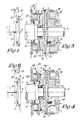
- Figure 3 is a view similar to that of Figure 1, except that it shows the design of a potential application;
- Figure 4 is a view similar to that of Figure 1, except that it shows the disengaged position as in Figure 2.
- The shot seeking mechanism as described by the invention consists primarily of two clutches, 1 and 2 respectively, placed between the
drive component 3 and the drivencomponent 4 of the main shaft of the machine, whereby thedrive component 3 of the main shaft is linked with afirst component 5 of clutch 1, while the drivencomponent 4 of the main shaft is linked simultaneously with both thesecond component 6 of clutch 1 and thefirst component 7 of clutch 2. - In this representation, the
second component 8 of clutch 2 is placed so that it can rotate very freely around theaforementioned component 4 of the main shaft and is linked by a gearwheel 9 which is connected in an appropriate manner, for example by means of achain 10, with a gearwheel 11 which is firmly attached to theshaft 12 of amotor 13. - Figure 1 shows the position of clutches 1 and 2 during normal operation of the loom. The clutch units or
parts parts auxiliary motor 13 is in a position of rest. - Thus at this
instant component 3 of the main shaft is directly connected withcomponent 4 via clutch 1. - When the machine stops as a result of a weft fault,
components components - At this moment,
motor 13 is also started, thus enabling themain shaft 4 to be wound back, for example by one full revolution, after whichmotor 13 is stopped;components components - The result of this is that when the weft is stopped, the weft end is released, so that the weaver merely has to remove the broken shot, insert the weft end into the edge of the fabric once more, and start up the machine again.
- It is evident that in the same manner, by running
motor 13 continuously in the appropriate direction of rotation, the machine may be run (4) de I'arbre principal de la machine a tisser et un moteur d'entrainement auxiliaire (13); le dispositif est caractérisé par le fait que l'une des unites d'embrayage (6-7) de chacun des embrayages (1, 2) est fixé a un support commun (19), par rapport auquel I'autre des unités d'embrayage (5, 8) de chacun des embrayages (1, 2) peut être déplacé indépendamment, de manière a engager l'un des embrayages (1, 2) et à libérer l'autre, ou même d'engager les deux embrayages (1, 2) a la fois; l'une des unités d'embrayage mobiles (5) men- tionnées ci-dessus est fixée a un support (17) fixé à son tour à l'élément menant (3) de l'arbre principal de la machine a tisser; I'autre unite d'embrayage mobile (8) est fixée a une support (20) pouvant être commandé par le moteur d'en- trainement auxiliaire (13); le support commun (19) mentionné ci-dessus étant fixé a l'élément mené (4) de l'arbre principal de la machine a tisser. - 2. Dispositif de recherche du pas selon la revendication 1, et caractérisée par le fait que le support (20) commandé par le moteur d'entraine- ment auxiliaire (13) est muni d'une roue dentée (9) entraînée par un pignon (11) fixé sur I'arbre (12) du moteur (13) mentionné par I'intermédiaire d'une chaine (10).
- 3. Dispositif de recherche du pas selon l'une des revendications précédentes et caractérisé par le fait que les unités d'embrayage mobiles (5, 8) sont commandées par des electro-aimants. slowly forwards or backwards by engaging clutch 2 and disengaging clutch 1, which may be performed either automatically or manually.
- Clutches 1 and 2 may be operated by any means whatsoever, although this should preferably be performed by electromagnetic means.
- Although not limiting, the
clutch components - An example of an application is illustrated in Figures 3 and 4.
- Here, a
disc 14 is attached ontoshaft 3 in such a way that it may rotate freely with respect to anannular disc 15, attached to the machine frame, in whichmagnets 16 are fitted which, when activated, attract adisc 17 against the resistance ofsprings 18, for whichpurpose component 5 of clutch 1 is fitted ondisc 17. - In this application, a
disc 19, fitted withcomponent 6 of clutch 1 andcomponent 7 of clutch 2 is attached ontoshaft 4. - A freely rotating
disc 20 is mounted next todisc 19, for example by means of a ball bearing 21 whereby springs 22 attempt to holdcomponent 8 of clutch 2 free fromcomponent 7 of this clutch. -
Disc 20 can be moved with respect todisc 19 against the resistance ofsprings 22 by means ofmagnets 23 fitted in adisc 24 attached to the machine frame. -
Disc 20 is made up in the form of a gearwheel. - The operation of the application as shown in Figures 3 and 4 may be clearly seen from Figures 3 and 4 based on the description of Figures 1 and 2.
Claims (3)
Applications Claiming Priority (2)
| Application Number | Priority Date | Filing Date | Title |
|---|---|---|---|
| BE2/60385A BE899346A (en) | 1984-04-06 | 1984-04-06 | BOTTOM SEARCHING DEVICE. |
| BE2060385 | 1984-04-06 |
Publications (2)
| Publication Number | Publication Date |
|---|---|
| EP0161012A1 EP0161012A1 (en) | 1985-11-13 |
| EP0161012B1 true EP0161012B1 (en) | 1988-09-21 |
Family
ID=3865684
Family Applications (1)
| Application Number | Title | Priority Date | Filing Date |
|---|---|---|---|
| EP85200300A Expired EP0161012B1 (en) | 1984-04-06 | 1985-03-01 | Shot seeking mechanism for weaving looms |
Country Status (4)
| Country | Link |
|---|---|
| US (1) | US4592392A (en) |
| EP (1) | EP0161012B1 (en) |
| BE (1) | BE899346A (en) |
| DE (1) | DE3565133D1 (en) |
Cited By (1)
| Publication number | Priority date | Publication date | Assignee | Title |
|---|---|---|---|---|
| DE10318819A1 (en) * | 2003-04-17 | 2004-11-04 | Picanol N.V. | Synchronization of separate motor drives on loom uses an imaginary synchronization shaft to provide control signals |
Families Citing this family (17)
| Publication number | Priority date | Publication date | Assignee | Title |
|---|---|---|---|---|
| NL8600870A (en) * | 1986-04-07 | 1987-11-02 | Picanol Nv | DRIVE FOR WEAVING MACHINES. |
| EP0327613B1 (en) * | 1987-08-12 | 1992-09-16 | BORISCH, Fred | Power loom with a mechanical dobby loom |
| IT1223621B (en) * | 1987-12-30 | 1990-09-29 | Baruffaldi Spa | DOUBLE COUPLING JOINT, PARTICULARLY FOR WEAVING FRAMES |
| BE1004064A3 (en) * | 1989-06-29 | 1992-09-15 | Picanol Nv | WEAVING MACHINE WITH LOCKING. |
| BE1004896A3 (en) * | 1991-05-23 | 1993-02-16 | Picanol Nv | Method and apparatus for driving a weaving machine FOR THE SLOW LOOP. |
| EP0616062A1 (en) * | 1993-03-17 | 1994-09-21 | Sulzer RàTi Ag | Weft breakage repair in dummy shuttle loams |
| BE1009097A3 (en) * | 1995-02-07 | 1996-11-05 | Picanol Nv | Weaving machine with DRIVE. |
| FR2755155B1 (en) * | 1996-10-25 | 1998-12-11 | Warner France | DEVICE FORMING A COUPLING WITH TWO CLUTCHES IN PARTICULAR FOR A WEAVING MATERIAL |
| IT1290504B1 (en) * | 1997-03-28 | 1998-12-04 | Baruffaldi Spa | MOTORIZED CLUTCH FOR DRIVING DRIVEN SHAFTS OF TEXTILE MACHINES |
| IT1291311B1 (en) * | 1997-05-06 | 1999-01-07 | Baruffaldi Spa | JOINT FOR THE COUPLING IN ROTATION OF DRIVING SHAFTS OF REINFORCEMENT MACHINES AND FRAMES OF MACHINE TOOLS |
| IT1292069B1 (en) * | 1997-06-03 | 1999-01-25 | Vamatex Nuova Spa | SLOW GEAR SELECTION AND PITCH SEARCH DEVICE IN WEAVING LOOMS |
| IT1297940B1 (en) * | 1997-12-23 | 1999-12-20 | Vamatex Nuova Spa | PERFECTED MECHANISM OF SELECTION AND GRAFTING OF THE SLOW-SPEED AND SEARCH OF THE STEP |
| DE10302506A1 (en) * | 2003-01-23 | 2004-09-02 | Zf Friedrichshafen Ag | Electromagnetically operated double clutch / brake combination |
| DE102004045208A1 (en) * | 2004-09-17 | 2006-04-06 | Siemens Ag | loom |
| EP3341510B1 (en) * | 2015-08-26 | 2020-03-04 | Picanol | Drive mechanism for driving a heald frame of a weaving machine |
| CN108866760B (en) * | 2018-09-13 | 2020-09-22 | 山东日发纺织机械有限公司 | Automatic weft searching device of rapier loom |
| CN109274200B (en) * | 2018-11-05 | 2019-10-25 | 大庆市华禹石油机械制造有限公司 | A kind of motor output shaft connection bearing assembly |
Family Cites Families (9)
| Publication number | Priority date | Publication date | Assignee | Title |
|---|---|---|---|---|
| GB649032A (en) * | 1943-05-12 | 1951-01-17 | Guillaume Diederichs Fils De | Reversing gear for weaving looms |
| US3175665A (en) * | 1962-02-15 | 1965-03-30 | Bendix Corp | Electromagnetic friction clutch |
| AT257293B (en) * | 1965-05-25 | 1967-09-25 | Vyzk Ustav Bavlnarsky | Electromagnetic clutch |
| GB1390377A (en) * | 1971-05-07 | 1975-04-09 | Nuovo Pignone Spa | Looms |
| DE2509665A1 (en) * | 1975-03-06 | 1976-09-09 | Lentz Textilmaschinen Gmbh | Loom reverse drive system - for eg dobby or jacquard looms, enabling weaving faults to be rectified |
| CH648881A5 (en) * | 1980-10-20 | 1985-04-15 | Staeubli Ag | SHOT SEARCH DEVICE WITH CREEPER. |
| FR2520762A1 (en) * | 1982-01-29 | 1983-08-05 | Staubli Sa Ets | IMPROVEMENTS IN DEVICES FOR SEARCHING FOR STEP ASSOCIATED WITH RATIERS AND OTHER WEAVING MECHANICS |
| IT1149570B (en) * | 1982-02-09 | 1986-12-03 | Fimtessile | IMPROVED DEVICE FOR THE SEARCH OF THE PITCH OF THE REINFORCEMENT MACHINES IN WEAVING FRAMES |
| DE19549084A1 (en) * | 1995-12-29 | 1997-07-03 | Wacker Chemie Gmbh | Powdery, redispersible binders |
-
1984
- 1984-04-06 BE BE2/60385A patent/BE899346A/en not_active IP Right Cessation
-
1985
- 1985-03-01 EP EP85200300A patent/EP0161012B1/en not_active Expired
- 1985-03-01 DE DE8585200300T patent/DE3565133D1/en not_active Expired
- 1985-03-11 US US06/710,692 patent/US4592392A/en not_active Expired - Fee Related
Cited By (1)
| Publication number | Priority date | Publication date | Assignee | Title |
|---|---|---|---|---|
| DE10318819A1 (en) * | 2003-04-17 | 2004-11-04 | Picanol N.V. | Synchronization of separate motor drives on loom uses an imaginary synchronization shaft to provide control signals |
Also Published As
| Publication number | Publication date |
|---|---|
| US4592392A (en) | 1986-06-03 |
| DE3565133D1 (en) | 1988-10-27 |
| EP0161012A1 (en) | 1985-11-13 |
| BE899346A (en) | 1984-10-08 |
Similar Documents
| Publication | Publication Date | Title |
|---|---|---|
| EP0161012B1 (en) | Shot seeking mechanism for weaving looms | |
| US4875565A (en) | Coupling with two clutches, especially for looms | |
| JP4187280B2 (en) | Loom drive unit | |
| US4509629A (en) | Plural motor plural clutch with worm drive | |
| EP0514959B1 (en) | Method and device for driving a weaving machine during the slow motion | |
| US4424835A (en) | Weaving error correction device for shuttleless weaving machine | |
| US4657051A (en) | Weaving machine | |
| US5046534A (en) | Weaving machine with main shaft lock | |
| US4478254A (en) | Device for actuating shedding motion searching and slow speed operation on a loom | |
| US7857011B2 (en) | Drive for a web machine | |
| US5404916A (en) | Loom method and apparatus for avoiding beat up markings in a fabric | |
| EP0877111B1 (en) | Coupling for rotationally connecting together the drive shafts of weave machines and weaving looms | |
| EP0241076B1 (en) | Drivesystem for weaving looms | |
| EP1191137B1 (en) | Coupling for rotationally connecting actuating shafts of weave machines and weaving looms | |
| EP1600542A2 (en) | Control device for textile weaving looms | |
| US3828824A (en) | Device for engaging and disengaging the dobby shaft and picking shaft of looms | |
| EP0086999A1 (en) | Device for synchronizing the shedding device in a loom | |
| EP0869210A1 (en) | Motorized clutch for operating driven shafts of weaving machines | |
| JPH0243908Y2 (en) | ||
| US4569374A (en) | Device for stopping the cloth takeup regulator in a weaving loom | |
| EP1096048A2 (en) | Automatic needle loom for the manufacture of ribbons | |
| JPH052630Y2 (en) | ||
| EP1469109B9 (en) | Slow-gear and pick-finding clutch having an improved magnetic flux and manufacturing method therefor | |
| KR910000354Y1 (en) | Slow actuating device for magic tape loom | |
| JPS6028553A (en) | Warp yarn feed apparatus of loom |
Legal Events
| Date | Code | Title | Description |
|---|---|---|---|
| PUAI | Public reference made under article 153(3) epc to a published international application that has entered the european phase |
Free format text: ORIGINAL CODE: 0009012 |
|
| AK | Designated contracting states |
Designated state(s): CH DE FR GB IT LI NL |
|
| 17P | Request for examination filed |
Effective date: 19851202 |
|
| RAP1 | Party data changed (applicant data changed or rights of an application transferred) |
Owner name: PICANOL N.V. |
|
| 17Q | First examination report despatched |
Effective date: 19870514 |
|
| GRAA | (expected) grant |
Free format text: ORIGINAL CODE: 0009210 |
|
| AK | Designated contracting states |
Kind code of ref document: B1 Designated state(s): CH DE FR GB IT LI NL |
|
| REF | Corresponds to: |
Ref document number: 3565133 Country of ref document: DE Date of ref document: 19881027 |
|
| ET | Fr: translation filed | ||
| ITF | It: translation for a ep patent filed | ||
| PLBI | Opposition filed |
Free format text: ORIGINAL CODE: 0009260 |
|
| 26 | Opposition filed |
Opponent name: DOTT. ING. PROF. A. RAIMONDI Effective date: 19890602 |
|
| NLR1 | Nl: opposition has been filed with the epo |
Opponent name: DOTT. ING. PROF. A. RAIMONDI |
|
| PGFP | Annual fee paid to national office [announced via postgrant information from national office to epo] |
Ref country code: DE Payment date: 19900518 Year of fee payment: 6 |
|
| PGFP | Annual fee paid to national office [announced via postgrant information from national office to epo] |
Ref country code: FR Payment date: 19910221 Year of fee payment: 7 |
|
| PGFP | Annual fee paid to national office [announced via postgrant information from national office to epo] |
Ref country code: GB Payment date: 19910301 Year of fee payment: 7 |
|
| PGFP | Annual fee paid to national office [announced via postgrant information from national office to epo] |
Ref country code: CH Payment date: 19910320 Year of fee payment: 7 |
|
| ITTA | It: last paid annual fee | ||
| PGFP | Annual fee paid to national office [announced via postgrant information from national office to epo] |
Ref country code: NL Payment date: 19910331 Year of fee payment: 7 |
|
| RDAG | Patent revoked |
Free format text: ORIGINAL CODE: 0009271 |
|
| STAA | Information on the status of an ep patent application or granted ep patent |
Free format text: STATUS: PATENT REVOKED |
|
| 27W | Patent revoked |
Effective date: 19910315 |
|
| GBPR | Gb: patent revoked under art. 102 of the ep convention designating the uk as contracting state | ||
| REG | Reference to a national code |
Ref country code: CH Ref legal event code: PL |
|
| NLR2 | Nl: decision of opposition |