EP0159764B1 - A fastener for installing a sheet such as a lath spaced from a support - Google Patents
A fastener for installing a sheet such as a lath spaced from a support Download PDFInfo
- Publication number
- EP0159764B1 EP0159764B1 EP85300241A EP85300241A EP0159764B1 EP 0159764 B1 EP0159764 B1 EP 0159764B1 EP 85300241 A EP85300241 A EP 85300241A EP 85300241 A EP85300241 A EP 85300241A EP 0159764 B1 EP0159764 B1 EP 0159764B1
- Authority
- EP
- European Patent Office
- Prior art keywords
- screw
- support
- coil
- lath
- spacing element
- Prior art date
- Legal status (The legal status is an assumption and is not a legal conclusion. Google has not performed a legal analysis and makes no representation as to the accuracy of the status listed.)
- Expired
Links
Images
Classifications
-
- F—MECHANICAL ENGINEERING; LIGHTING; HEATING; WEAPONS; BLASTING
- F16—ENGINEERING ELEMENTS AND UNITS; GENERAL MEASURES FOR PRODUCING AND MAINTAINING EFFECTIVE FUNCTIONING OF MACHINES OR INSTALLATIONS; THERMAL INSULATION IN GENERAL
- F16B—DEVICES FOR FASTENING OR SECURING CONSTRUCTIONAL ELEMENTS OR MACHINE PARTS TOGETHER, e.g. NAILS, BOLTS, CIRCLIPS, CLAMPS, CLIPS OR WEDGES; JOINTS OR JOINTING
- F16B35/00—Screw-bolts; Stay-bolts; Screw-threaded studs; Screws; Set screws
- F16B35/04—Screw-bolts; Stay-bolts; Screw-threaded studs; Screws; Set screws with specially-shaped head or shaft in order to fix the bolt on or in an object
- F16B35/041—Specially-shaped shafts
- F16B35/048—Specially-shaped necks
-
- B—PERFORMING OPERATIONS; TRANSPORTING
- B25—HAND TOOLS; PORTABLE POWER-DRIVEN TOOLS; MANIPULATORS
- B25B—TOOLS OR BENCH DEVICES NOT OTHERWISE PROVIDED FOR, FOR FASTENING, CONNECTING, DISENGAGING, OR HOLDING
- B25B21/00—Portable power-driven screw or nut setting or loosening tools; Attachments for drilling apparatus serving the same purpose
-
- B—PERFORMING OPERATIONS; TRANSPORTING
- B25—HAND TOOLS; PORTABLE POWER-DRIVEN TOOLS; MANIPULATORS
- B25B—TOOLS OR BENCH DEVICES NOT OTHERWISE PROVIDED FOR, FOR FASTENING, CONNECTING, DISENGAGING, OR HOLDING
- B25B23/00—Details of, or accessories for, spanners, wrenches, screwdrivers
-
- E—FIXED CONSTRUCTIONS
- E04—BUILDING
- E04F—FINISHING WORK ON BUILDINGS, e.g. STAIRS, FLOORS
- E04F13/00—Coverings or linings, e.g. for walls or ceilings
- E04F13/02—Coverings or linings, e.g. for walls or ceilings of plastic materials hardening after applying, e.g. plaster
- E04F13/04—Bases for plaster
- E04F13/045—Means for fastening plaster-bases to a supporting structure
-
- F—MECHANICAL ENGINEERING; LIGHTING; HEATING; WEAPONS; BLASTING
- F16—ENGINEERING ELEMENTS AND UNITS; GENERAL MEASURES FOR PRODUCING AND MAINTAINING EFFECTIVE FUNCTIONING OF MACHINES OR INSTALLATIONS; THERMAL INSULATION IN GENERAL
- F16B—DEVICES FOR FASTENING OR SECURING CONSTRUCTIONAL ELEMENTS OR MACHINE PARTS TOGETHER, e.g. NAILS, BOLTS, CIRCLIPS, CLAMPS, CLIPS OR WEDGES; JOINTS OR JOINTING
- F16B5/00—Joining sheets or plates, e.g. panels, to one another or to strips or bars parallel to them
- F16B5/02—Joining sheets or plates, e.g. panels, to one another or to strips or bars parallel to them by means of fastening members using screw-thread
- F16B5/0216—Joining sheets or plates, e.g. panels, to one another or to strips or bars parallel to them by means of fastening members using screw-thread the position of the plates to be connected being adjustable
- F16B5/0233—Joining sheets or plates, e.g. panels, to one another or to strips or bars parallel to them by means of fastening members using screw-thread the position of the plates to be connected being adjustable allowing for adjustment perpendicular to the plane of the plates
Definitions
- This invention relates to the attachment of a sheet such as an expanded metal lath to a support.
- the invention involves the use of a screw and spacing means to leave a space between the lath and the support.
- a fastener for attaching a lath to a support comprises a screw having a shank with at least one thread on it, an enlarged head at one end of the shank and a tip at the other end, and spacing means for engaging the lath and holding it away from the support.
- US-A-1701095 discloses a spacer used in connecting a metal lath to a support.
- the spacer comprises a generally helically shaped member having a central through bore, a lower portion with abutment means to prevent penetration of the spacer into the support, and an outer portion forming a tapering helix with a larger end and a smaller end.
- the smaller end is adapted initially to engage an opening in the lath whereby movement of the spacer causes it to pass through the lath and occupy a space between the lath and on the support.
- FR-A-2178985 discloses a fastener for attaching a sheet to a support comprising a screw having a shank with a thread on it, an enlarged head at one end of the shank and a tip at the other end, and spacing means for engaging the member and holding it away from the support, the spacing means including a helical portion having a pitch and a diameter, each of which is greater than the pitch and diameter of the thread on the shank.
- a fastener as disclosed in FR-A-2178985 is characterised in that the sheet is a metal lath, the pitch and diameter of the helical portion are at least twice the pitch and diameter respectively of the thread and the spacing means comprises a helical coil which has a lower portion nearer the tip at least one helical turn of which mates with the thread on the shank of the screw, and an upper portion of larger diameter which forms the helical portion, the lower portion enabling the coil to be preassembled with the screw and located initially adjacent the tip of the screw.
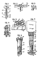
- Figures 1, 2 and 3 show a screw 10 with a head 12 and a drill tip 14.
- a spacing element 16 is preassembled to the screw 10 at a location on the shank of the screw adjacent the tip 14.
- the spacing element 16 includes an enlarged upper portion 18 and a smaller lower portion 20.
- the lower portion 20 is preferably at least in partial engagement with threads 22 on the screw 10.
- the spacing element 16 is comprised of a coil made from round wire.
- the lower end 24 includes a sharp edge 26 which is adapted to engage a metal support 28.
- FIG. 2 shows the fastener of the present invention in an installed position.
- Lath 30 is held away from the metal support 28.
- the drill tip 14 of the screw 10 is adapted to form a hole in the support 28.
- the spacing element 16 threadingly engages and penetrates the lath 30.
- the edge 26 of the lower end 24 of the spacing element 16 engages the metal support 28 and prevents the penetration of the spacing element 16 into the support 28.
- engagement between the edge 26 and the support 28 causes the spacing element to stop its rotation.
- Continued axial advancement of the screw 10 through the spacing element 16 and the support 28 eventually causes the lath 30 to be clamped between the spacing element 16 and the head 12 of the screw.
- the spacing element is in moderately tight engagement with the lower portion of the screw. This moderately tight or gripping engagement allows rotation of the head 12 of the screw to be transferred to the spacing element 16 as drilling takes place. Once drilling is completed and threaded engagement between the threads 22 and the support 28 begins to take place, abutment between the end 24 of the spacing element 16 and the support 28 causes a slight release of the gripping action between the spacing element and the screw. The release of the engagement between the spacing element 16 and the screw 10 allows the axial advancement of the screw through the spacing element 16 and into the support 28.
- the sharp edge 26 is specifically adapted to engage a metallic support 28.
- Figures 4 and 5 show a slightly modified version of the preferred embodiment.
- the embodiment of Figures 4 and 5 is specifically adapted for use with wall construction in which a non-metallic surface member 49, such as drywall or particle board, has been previously attached to a metal support 48.
- Figure 4 shows a coil spacing element 36 with an enlarged upper portion 38 and a smaller lower portion 40.
- the lower end 44 of the spacing element 36 is slightly enlarged and bent to provide a blunt abutment 46.
- the operation of the fastener shown in Figures 4 and 5 is similar to that shown in Figures 1 through 3.
- the spacing element 36 is firmly preassembled to the lower threaded portion of a screw 10. As the tip 14 of the screw 10 is placed against the member 49 and rotated, the helical spacing element 36 threadingly engages the lath 30. The abutment 46 at the lower end of the spacing element 36 prevents the penetration of the spacing element into the member 49. The spacing element 36 is thereby lodged between the lath and the support. The screw 10 axially advances through the spacing element 36, through the member 49 and through the support 48, and the lath 30 is clamped between the upper portion 38 of the spacing element 36 and the head 12 of the screw 10.
- the coil spacing element is generally in the form of a tapering helix.
- the number of turns at the lower portion of the spacing element may be varied. It is desirable, however, that the spacing element be capable of preassembly with a screw.
- the number of turns of the coil which are in registration with the threads of the screw, as well as the height and lateral extent of the enlarged upper portion of the spacing element will depend upon the type of lath being fastened. Smaller gauge lath may require that the expanded upper portion of the spacing element extend to a point near the lower portion of the spacing element in order to assure threading engagement between the spacing element and the lath.
- the lateral size of the upper portion of the spacing element will depend upon the size of the openings in the lath.
- the lateral size of the spacing element is preferably at least as large if not larger than the openings 31 in the lath 30. This is necessary to ensure that the lath will be held by the spacing element away from the support.
- FIGS. 6 and 7 show a nosepiece designed to cooperate with the above described embodiments of the present invention.
- the nosepiece 80 is comprised of a threaded collar 81 adapted to threadingly engage a driving tool 90.
- the nosepiece also includes two telescoping tubular elements 83 and 84.
- a coil spring 85 within the upper tubular element 83 urges the lower element 84 into an extended position.
- Prongs 86 are rigidly fixed to the free end of the lower element 84.
- the prongs 86 are adapted to penetrate openings 31 in the lath 30 and abut the support 48.
- a torque transmitting bit 91 associated with the tool 90 engages a recess in the head 12 of the screw 10.
- the tubular elements 83 and 84 telescopically collapse.
- the telescoping movement of the elements 83 and 84 is limited, however, so that axial movement of the bit 91 is limited.
- the screw 10 will disengage from the bit 91 and further rotation of the screw will stop.
- the prongs 86 and the lower element 84 therefore define a torque-limiting recess 87 which prevents the application of excessive compressive force upon the spacing element 36.
Landscapes
- Engineering & Computer Science (AREA)
- Mechanical Engineering (AREA)
- General Engineering & Computer Science (AREA)
- Architecture (AREA)
- Civil Engineering (AREA)
- Structural Engineering (AREA)
- Connection Of Plates (AREA)
- Dowels (AREA)
- Portable Nailing Machines And Staplers (AREA)
- Clamps And Clips (AREA)
Abstract
Description
- This invention relates to the attachment of a sheet such as an expanded metal lath to a support. In particular, the invention involves the use of a screw and spacing means to leave a space between the lath and the support.
- At present a fastener for attaching a lath to a support comprises a screw having a shank with at least one thread on it, an enlarged head at one end of the shank and a tip at the other end, and spacing means for engaging the lath and holding it away from the support.
- Current techniques for attaching a lath have been found to be quite unsatisfactory. Installers of lath frequently use scrap material as the spacing means or shim between the lath and the support, and then apply standard screws to hold the lath against the shim. With this technique, it is frequently the case that a workman will not provide a space between the lath and its support because scrap material may not be available, or because it may be difficult to hold a shim in place while installing a piece of lath of significant lateral extent. It should be noted that architects and building codes usually require that a space be provided between the lath and a support. The spacing is important because it provides a place for plaster to extrude when it is applied to the lath to form a key. Without proper spacing at locations where the lath is supported, the thickness of the plaster will not be sufficient, and unsightly cracking is much more likely to occur.
- US-A-1701095 discloses a spacer used in connecting a metal lath to a support. The spacer comprises a generally helically shaped member having a central through bore, a lower portion with abutment means to prevent penetration of the spacer into the support, and an outer portion forming a tapering helix with a larger end and a smaller end. The smaller end is adapted initially to engage an opening in the lath whereby movement of the spacer causes it to pass through the lath and occupy a space between the lath and on the support.
- FR-A-2178985 discloses a fastener for attaching a sheet to a support comprising a screw having a shank with a thread on it, an enlarged head at one end of the shank and a tip at the other end, and spacing means for engaging the member and holding it away from the support, the spacing means including a helical portion having a pitch and a diameter, each of which is greater than the pitch and diameter of the thread on the shank.
- According to this invention a fastener as disclosed in FR-A-2178985 is characterised in that the sheet is a metal lath, the pitch and diameter of the helical portion are at least twice the pitch and diameter respectively of the thread and the spacing means comprises a helical coil which has a lower portion nearer the tip at least one helical turn of which mates with the thread on the shank of the screw, and an upper portion of larger diameter which forms the helical portion, the lower portion enabling the coil to be preassembled with the screw and located initially adjacent the tip of the screw.
- A fastener in accordance with this invention will now be described with reference to the accompanying drawings; in which:-
- Figure 1 is a perspective view of a first example of fastener;
- Figure 2 is a side elevation of the first example after installation;
- Figure 3 is a side elevation of the tip of the first example;
- Figure 4 is a side elevation part of a second example;
- Figure 5 is a perspective view of the second example after installation;
- Figure 6 is a perspective view of a nosepiece; and,
- Figure 7 is a side elevation of the nosepiece in use.
- Referring now to the drawings in which the same numerals are used for similar parts throughout the various figures, Figures 1, 2 and 3 show a
screw 10 with ahead 12 and adrill tip 14. Aspacing element 16 is preassembled to thescrew 10 at a location on the shank of the screw adjacent thetip 14. Thespacing element 16 includes an enlargedupper portion 18 and a smallerlower portion 20. Thelower portion 20 is preferably at least in partial engagement withthreads 22 on thescrew 10. Thespacing element 16 is comprised of a coil made from round wire. Thelower end 24 includes asharp edge 26 which is adapted to engage ametal support 28. - Figure 2 shows the fastener of the present invention in an installed position. Lath 30 is held away from the
metal support 28. Thedrill tip 14 of thescrew 10 is adapted to form a hole in thesupport 28. During the several revolutions required to form the hole in the support, thespacing element 16 threadingly engages and penetrates thelath 30. Theedge 26 of thelower end 24 of thespacing element 16 engages themetal support 28 and prevents the penetration of thespacing element 16 into thesupport 28. When thescrew 10 begins to penetrate and threadingly advance through thesupport 28, engagement between theedge 26 and thesupport 28 causes the spacing element to stop its rotation. Continued axial advancement of thescrew 10 through thespacing element 16 and thesupport 28 eventually causes thelath 30 to be clamped between thespacing element 16 and thehead 12 of the screw. - It should be noted that in the preferred embodiment, the spacing element is in moderately tight engagement with the lower portion of the screw. This moderately tight or gripping engagement allows rotation of the
head 12 of the screw to be transferred to thespacing element 16 as drilling takes place. Once drilling is completed and threaded engagement between thethreads 22 and thesupport 28 begins to take place, abutment between theend 24 of thespacing element 16 and thesupport 28 causes a slight release of the gripping action between the spacing element and the screw. The release of the engagement between thespacing element 16 and thescrew 10 allows the axial advancement of the screw through thespacing element 16 and into thesupport 28. Thesharp edge 26 is specifically adapted to engage ametallic support 28. - Figures 4 and 5 show a slightly modified version of the preferred embodiment. The embodiment of Figures 4 and 5 is specifically adapted for use with wall construction in which a
non-metallic surface member 49, such as drywall or particle board, has been previously attached to ametal support 48. Figure 4 shows acoil spacing element 36 with an enlargedupper portion 38 and a smallerlower portion 40. Thelower end 44 of thespacing element 36 is slightly enlarged and bent to provide ablunt abutment 46. By providing ablunt abutment 46 at the lower end of thespacing element 36, penetration of the spacing element into themember 49 is prevented. The operation of the fastener shown in Figures 4 and 5 is similar to that shown in Figures 1 through 3. Thespacing element 36 is firmly preassembled to the lower threaded portion of ascrew 10. As thetip 14 of thescrew 10 is placed against themember 49 and rotated, thehelical spacing element 36 threadingly engages thelath 30. Theabutment 46 at the lower end of thespacing element 36 prevents the penetration of the spacing element into themember 49. Thespacing element 36 is thereby lodged between the lath and the support. Thescrew 10 axially advances through thespacing element 36, through themember 49 and through thesupport 48, and thelath 30 is clamped between theupper portion 38 of thespacing element 36 and thehead 12 of thescrew 10. - In the preferred embodiment of the present invention, shown in Figures 1 through 5, it should be noted that the coil spacing element is generally in the form of a tapering helix. The number of turns at the lower portion of the spacing element may be varied. It is desirable, however, that the spacing element be capable of preassembly with a screw. The number of turns of the coil which are in registration with the threads of the screw, as well as the height and lateral extent of the enlarged upper portion of the spacing element will depend upon the type of lath being fastened. Smaller gauge lath may require that the expanded upper portion of the spacing element extend to a point near the lower portion of the spacing element in order to assure threading engagement between the spacing element and the lath. Similarly, the lateral size of the upper portion of the spacing element will depend upon the size of the openings in the lath. The lateral size of the spacing element is preferably at least as large if not larger than the openings 31 in the
lath 30. This is necessary to ensure that the lath will be held by the spacing element away from the support. - Figures 6 and 7 show a nosepiece designed to cooperate with the above described embodiments of the present invention. The
nosepiece 80 is comprised of a threadedcollar 81 adapted to threadingly engage adriving tool 90. The nosepiece also includes two telescopingtubular elements coil spring 85 within the uppertubular element 83 urges thelower element 84 into an extended position.Prongs 86 are rigidly fixed to the free end of thelower element 84. Theprongs 86 are adapted to penetrate openings 31 in thelath 30 and abut thesupport 48. Atorque transmitting bit 91 associated with thetool 90 engages a recess in thehead 12 of thescrew 10. As the screw is advanced through thespacing element 36 and into thesupport 48, thetubular elements elements bit 91 is limited. At a predetermined axial position, thescrew 10 will disengage from thebit 91 and further rotation of the screw will stop. Theprongs 86 and thelower element 84 therefore define a torque-limitingrecess 87 which prevents the application of excessive compressive force upon thespacing element 36. By limiting the axial movement of thebit 91, and therefore thehead 12, thelath 30 is maintained at a predetermined distance from thesupport 48. - It is clear that alternative methods of limiting the axial penetration of the
screw 10 are available. Examples include forming a shoulder on the shank of the screw at a predetermined distance from the head to prevent penetration of the screw into the support.
Claims (6)
Priority Applications (1)
| Application Number | Priority Date | Filing Date | Title |
|---|---|---|---|
| AT85300241T ATE42986T1 (en) | 1984-01-16 | 1985-01-14 | SCREW FOR FIXING A PLATE LIKE A PLASTER BEARER AT A DISTANCE FROM A BEARER. |
Applications Claiming Priority (2)
| Application Number | Priority Date | Filing Date | Title |
|---|---|---|---|
| US571303 | 1984-01-16 | ||
| US06/571,303 US4581871A (en) | 1984-01-16 | 1984-01-16 | Fastener and nosepiece for installing lath |
Publications (3)
| Publication Number | Publication Date |
|---|---|
| EP0159764A2 EP0159764A2 (en) | 1985-10-30 |
| EP0159764A3 EP0159764A3 (en) | 1986-03-05 |
| EP0159764B1 true EP0159764B1 (en) | 1989-05-10 |
Family
ID=24283127
Family Applications (1)
| Application Number | Title | Priority Date | Filing Date |
|---|---|---|---|
| EP85300241A Expired EP0159764B1 (en) | 1984-01-16 | 1985-01-14 | A fastener for installing a sheet such as a lath spaced from a support |
Country Status (5)
| Country | Link |
|---|---|
| US (1) | US4581871A (en) |
| EP (1) | EP0159764B1 (en) |
| AT (1) | ATE42986T1 (en) |
| CA (1) | CA1249739A (en) |
| DE (1) | DE3570100D1 (en) |
Cited By (1)
| Publication number | Priority date | Publication date | Assignee | Title |
|---|---|---|---|---|
| US7921617B2 (en) | 2001-08-30 | 2011-04-12 | Stevens Donald A | Structural panel utilizing a lath and frame member and method for making the same |
Families Citing this family (16)
| Publication number | Priority date | Publication date | Assignee | Title |
|---|---|---|---|---|
| US4952110A (en) * | 1989-10-13 | 1990-08-28 | Ring Screw Works, Inc. | Anti-cross thread screw |
| US5006023A (en) * | 1990-04-24 | 1991-04-09 | Stanley Kaplan | Strip-out preventing anchoring assembly and method of anchoring |
| DE4445813C2 (en) * | 1994-12-21 | 1996-12-05 | Sfs Ind Holding Ag | Attachment for a machine working with an axial impact |
| US5919193A (en) * | 1996-03-14 | 1999-07-06 | Slavitt; Jerome A. | Method and kit for surgically correcting malformations in digits of a finger or toe |
| US6363679B1 (en) | 1999-06-11 | 2002-04-02 | Flannery, Inc. | Fastening device |
| GB9926968D0 (en) * | 1999-11-15 | 2000-01-12 | Univ London | Treatment of neurological disorders |
| JP4280773B2 (en) * | 2004-03-30 | 2009-06-17 | 中央発条工業株式会社 | Locking nut |
| EP1904752B1 (en) * | 2005-07-21 | 2009-10-28 | Pama Reiter Stefan | Fixing element for anchoring in massive bases |
| US20080118332A1 (en) * | 2006-11-16 | 2008-05-22 | David Lamb | Drywall screw |
| USD601004S1 (en) * | 2008-09-26 | 2009-09-29 | Tyrone Hagins | Head screw |
| US20100180541A1 (en) * | 2009-01-20 | 2010-07-22 | Chong Ming Lee | Reusable Expansion Anchoring Assembly and Setting Method Thereof |
| US8894334B2 (en) * | 2010-12-17 | 2014-11-25 | Illinois Tool Works Inc. | Helical rolled ring bolt |
| DE202011052036U1 (en) * | 2011-11-18 | 2013-02-20 | Jörg Schwarzbich | Tolerance compensation element |
| DE202013104266U1 (en) | 2013-09-18 | 2015-01-09 | Jörg Schwarzbich | Arrangement for connecting components |
| KR101560737B1 (en) * | 2014-07-23 | 2015-10-15 | 황재필 | Locking bolt |
| US11476530B2 (en) * | 2020-03-10 | 2022-10-18 | Karma Automotive Llc | Vehicle battery assembly |
Family Cites Families (15)
| Publication number | Priority date | Publication date | Assignee | Title |
|---|---|---|---|---|
| US1264677A (en) * | 1917-01-20 | 1918-04-30 | Murrell Fastener Company | Securing device. |
| US1640303A (en) * | 1922-12-09 | 1927-08-23 | Economy Products Corp | Wall construction |
| US1546522A (en) * | 1923-01-02 | 1925-07-21 | George F Voight | Wall construction |
| US1703557A (en) * | 1923-12-26 | 1929-02-26 | John L Sullivan | Furring and fastening device |
| US1701095A (en) * | 1927-04-08 | 1929-02-05 | Pittsburgh Steel Co | Wire-fastening device |
| US2575731A (en) * | 1948-06-12 | 1951-11-20 | Santa Antonio | Elastic fastening means for spectacle lenses |
| GB646671A (en) * | 1948-10-26 | 1950-11-29 | Oscar Valdemar Malmkvist | Improvements in or relating to screw-anchors intended to be moulded into a wall or the like supporting structure |
| DE1137197B (en) * | 1960-08-09 | 1962-09-27 | Artur Fischer | Attachment of door frame frames, window frames or similar wooden components to the masonry using dowels and screws |
| US3376683A (en) * | 1965-10-23 | 1968-04-09 | Alside Inc | Leveling means for aluminum siding panel |
| GB1367082A (en) * | 1970-10-05 | 1974-09-18 | Ft Products Ltd | Threaded fastener |
| CH559320A5 (en) * | 1971-12-31 | 1975-02-28 | Muetzenberg Arnold B | Connecting element for sheet workpieces etc. - consists of threaded bolt with coiled wire screwed onto threads |
| DE2216522A1 (en) * | 1972-04-06 | 1973-10-11 | Artur Fischer | DEVICE FOR FASTENING COMPONENTS SPACING |
| US4309135A (en) * | 1980-07-18 | 1982-01-05 | Keystone Consolidated Industries, Inc. | Concrete anchor |
| DE3037606C2 (en) * | 1980-10-04 | 1982-11-25 | Daimler-Benz Ag, 7000 Stuttgart | Spacer made of plastic |
| US4437784A (en) * | 1982-01-28 | 1984-03-20 | Illinois Tool Works Inc. | Adjustable shim system |
-
1984
- 1984-01-16 US US06/571,303 patent/US4581871A/en not_active Expired - Fee Related
-
1985
- 1985-01-08 CA CA000471682A patent/CA1249739A/en not_active Expired
- 1985-01-14 AT AT85300241T patent/ATE42986T1/en active
- 1985-01-14 DE DE8585300241T patent/DE3570100D1/en not_active Expired
- 1985-01-14 EP EP85300241A patent/EP0159764B1/en not_active Expired
Cited By (1)
| Publication number | Priority date | Publication date | Assignee | Title |
|---|---|---|---|---|
| US7921617B2 (en) | 2001-08-30 | 2011-04-12 | Stevens Donald A | Structural panel utilizing a lath and frame member and method for making the same |
Also Published As
| Publication number | Publication date |
|---|---|
| EP0159764A3 (en) | 1986-03-05 |
| DE3570100D1 (en) | 1989-06-15 |
| ATE42986T1 (en) | 1989-05-15 |
| CA1249739A (en) | 1989-02-07 |
| EP0159764A2 (en) | 1985-10-30 |
| US4581871A (en) | 1986-04-15 |
Similar Documents
| Publication | Publication Date | Title |
|---|---|---|
| US4581871A (en) | Fastener and nosepiece for installing lath | |
| US6186716B1 (en) | Anchor bolt | |
| EP0414335B1 (en) | Self-drilling wall anchor | |
| US5625994A (en) | Self-drilling anchor | |
| US4601625A (en) | Self drilling threaded insert for drywall | |
| EP0461790B1 (en) | Anchor bolt | |
| EP2623797B1 (en) | Anchor and method of installing anchor | |
| EP0305868A1 (en) | Blind fastener | |
| JPH1047325A (en) | Self drilling / self tapping fastener | |
| GB2043817A (en) | Metal insert screw socket | |
| EP1049879B1 (en) | A mounting device | |
| US11867210B2 (en) | Expansion-type anchor, sleeve used in same, and construction method | |
| GB2124528A (en) | A masonry anchor | |
| US4789282A (en) | Expansion anchor stud | |
| US5558480A (en) | Bolt for truss, wherein the bolt has shaft portions separated by a groove and a stopper having protrusions engaged in the groove | |
| US3837257A (en) | Anchoring device | |
| US5688090A (en) | Screw assembly | |
| CN113124031A (en) | Anchor bolt for inner wall | |
| EP0516295A1 (en) | Masonry anchor installation tool | |
| US20040109741A1 (en) | Toggle bolt method and apparatus | |
| EP0378907B1 (en) | Blind anchors for fixing screws | |
| EP0626041B1 (en) | Masonry anchors | |
| JP3884134B2 (en) | Anchor bracket | |
| EP0158304A1 (en) | Fastener | |
| EP0412257B1 (en) | Expansion plug |
Legal Events
| Date | Code | Title | Description |
|---|---|---|---|
| PUAI | Public reference made under article 153(3) epc to a published international application that has entered the european phase |
Free format text: ORIGINAL CODE: 0009012 |
|
| AK | Designated contracting states |
Designated state(s): AT BE CH DE FR GB IT LI LU NL SE |
|
| PUAL | Search report despatched |
Free format text: ORIGINAL CODE: 0009013 |
|
| AK | Designated contracting states |
Kind code of ref document: A3 Designated state(s): AT BE CH DE FR GB IT LI LU NL SE |
|
| 17P | Request for examination filed |
Effective date: 19860819 |
|
| 17Q | First examination report despatched |
Effective date: 19870514 |
|
| GRAA | (expected) grant |
Free format text: ORIGINAL CODE: 0009210 |
|
| AK | Designated contracting states |
Kind code of ref document: B1 Designated state(s): AT BE CH DE FR GB IT LI LU NL SE |
|
| REF | Corresponds to: |
Ref document number: 42986 Country of ref document: AT Date of ref document: 19890515 Kind code of ref document: T |
|
| REF | Corresponds to: |
Ref document number: 3570100 Country of ref document: DE Date of ref document: 19890615 |
|
| ITF | It: translation for a ep patent filed | ||
| ET | Fr: translation filed | ||
| ITTA | It: last paid annual fee | ||
| PG25 | Lapsed in a contracting state [announced via postgrant information from national office to epo] |
Ref country code: LU Free format text: LAPSE BECAUSE OF NON-PAYMENT OF DUE FEES Effective date: 19900131 |
|
| PLBE | No opposition filed within time limit |
Free format text: ORIGINAL CODE: 0009261 |
|
| STAA | Information on the status of an ep patent application or granted ep patent |
Free format text: STATUS: NO OPPOSITION FILED WITHIN TIME LIMIT |
|
| 26N | No opposition filed | ||
| PGFP | Annual fee paid to national office [announced via postgrant information from national office to epo] |
Ref country code: DE Payment date: 19901217 Year of fee payment: 7 Ref country code: AT Payment date: 19901217 Year of fee payment: 7 |
|
| PGFP | Annual fee paid to national office [announced via postgrant information from national office to epo] |
Ref country code: CH Payment date: 19901218 Year of fee payment: 7 |
|
| PGFP | Annual fee paid to national office [announced via postgrant information from national office to epo] |
Ref country code: SE Payment date: 19901219 Year of fee payment: 7 |
|
| PGFP | Annual fee paid to national office [announced via postgrant information from national office to epo] |
Ref country code: LU Payment date: 19901227 Year of fee payment: 7 Ref country code: BE Payment date: 19901227 Year of fee payment: 7 |
|
| PGFP | Annual fee paid to national office [announced via postgrant information from national office to epo] |
Ref country code: GB Payment date: 19910102 Year of fee payment: 7 |
|
| PGFP | Annual fee paid to national office [announced via postgrant information from national office to epo] |
Ref country code: NL Payment date: 19910131 Year of fee payment: 7 |
|
| EPTA | Lu: last paid annual fee | ||
| PGFP | Annual fee paid to national office [announced via postgrant information from national office to epo] |
Ref country code: FR Payment date: 19911212 Year of fee payment: 8 |
|
| PG25 | Lapsed in a contracting state [announced via postgrant information from national office to epo] |
Ref country code: GB Effective date: 19920114 Ref country code: AT Effective date: 19920114 |
|
| PG25 | Lapsed in a contracting state [announced via postgrant information from national office to epo] |
Ref country code: SE Effective date: 19920115 |
|
| PG25 | Lapsed in a contracting state [announced via postgrant information from national office to epo] |
Ref country code: LI Effective date: 19920131 Ref country code: CH Effective date: 19920131 Ref country code: BE Effective date: 19920131 |
|
| BERE | Be: lapsed |
Owner name: ILLINOIS TOOL WORKS INC. Effective date: 19920131 |
|
| PG25 | Lapsed in a contracting state [announced via postgrant information from national office to epo] |
Ref country code: NL Effective date: 19920801 |
|
| GBPC | Gb: european patent ceased through non-payment of renewal fee | ||
| NLV4 | Nl: lapsed or anulled due to non-payment of the annual fee | ||
| REG | Reference to a national code |
Ref country code: CH Ref legal event code: PL |
|
| PG25 | Lapsed in a contracting state [announced via postgrant information from national office to epo] |
Ref country code: DE Effective date: 19921001 |
|
| PG25 | Lapsed in a contracting state [announced via postgrant information from national office to epo] |
Ref country code: FR Effective date: 19930930 |
|
| REG | Reference to a national code |
Ref country code: FR Ref legal event code: ST |
|
| EUG | Se: european patent has lapsed |
Ref document number: 85300241.8 Effective date: 19920806 |